Open Access : : ISSN 1847-9286
www.jESE-online.org
Original scientific paper
Morphology and cyclic voltammetry analysis of in situ
polymerized polyaniline/graphene composites
DEVESH KUMAR MAHLA, SUBHENDU BHANDARI, MOSTAFIZUR RAHAMAN*
,
DIPAK KHASTGIR
Rubber Technology Centre, Indian Institute of Technology Kharagpur, Kharagpur, India *Presently at Chemical Engineering Department, College of Engineering Sciences, King Fahd University of Petroleum and Minerals (KFUPM), Dhahran, Saudi Arabia
Corresponding Authors: E-mail: mrahaman1997@gmail.com; khasdi@rtc.iitkgp.ernet.in
Received: April 28, 2013; Revised: August 10, 2013; Published: Novembar 09, 2013
Abstract
Graphene (G) was synthesized from normal graphite powder via graphene oxide (GO). Graphene was also produced from finer particles of graphite subjected to ball milling to check the effect of particle size of graphene on the properties of composite. PANI/graphene composites of different compositions were prepared by in situ polymerization of aniline to polyaniline in the presence of graphene powder. Graphene, graphene oxide and PANI/graphene composites were characterized by UV, IR, TEM, and cyclic voltammetry. PANI/graphene composites exhibit higher current in cyclic voltammetry study compared to either neat PANI or neat graphene. The value of capacitance achieved for PANI/graphene composites is found to depend on the size of graphene particles, finer the particle higher is the capacitance for the composites. However, the effect of composition on CV characteristics of composite is relatively less pronounced compared to the size of graphene sheets coated with PANI.
Keywords
Polyaniline; Graphene; Conductive composites; Cyclic voltammetry.
Introduction
graphite. Graphene, at large scale, is produced by reducing graphene oxide by some reducing agent. Graphene is having large aspect ratio (ratio of surface area to thickness) [11], high mechanical strength [12], high electrical conductivity [13], ability to disperse in polymers well [14], high thermal conductivity and stability [15]. It can be effectively exploited for many applications [16,17]. Graphene oxide derived from graphite through oxidation has many polar groups on its surface like –C=O, –COOH, –OH, which give its properties like hydrophilicity, dispersibility, and compatibility with many polymers.
Among conductive polymers, polyaniline (PANI) has attracted considerable attention because of its ease of preparation, low cost of monomer, good environmental stability, good conductivity control through doping as well as a good control of oxidation level. All these properties give PANI the potential for wide applications [18–22]. It can effectively be used as opto-electronic sensors [23–26], conductive paints and adhesive [27–29].
PANI has also good power and energy density, so it has been analyzed for the development of new supercapacitor materials [30–32]. Generally, electrochemical super capacitors are of two types; type-1 is electrical double layer capacitor (EDLC) due to charge separation at electrode/electrolyte interface, and type-2 is pseudocapacitor, where capacitance is due to both reversible faradic reaction and charge separation [33]. The latter category of capacitor materials can be further divided in to two different types of material based on their origin, for example i) metal oxide like RuO2 and ii) conducting polymer like PANI.
The energy and power density of power sources like batteries and capacitors can be shown by Ragone plot. Batteries have good energy density and EDLC type capacitors have good power density whereas pseudocapacitors work on the principle of both batteries and capacitors, simultaneously. PANI can act as a pseudocapacitor and it has the power to store energy by reversible chemical reactions, as observed in batteries, and also like EDLC. In polyaniline/graphene composite, graphene not only increases the EDLC capacity of PANI but also helps in facilitating charge transfer and consequently enhances the utilization of PANI as a capacitor material by increasing available surface area.
The scrutiny of available literatures reveals that there exist some reports on PANI/graphene composites. However, all these reports mainly deal with only one or at best two compositions of PANI/graphene system. The effect of size of graphene particles on the properties of PANI/graphene composites has not been extensively investigated. So the present study deals with synthesis and characterization of PANI/graphene composites with different compositions. The preparation of PANI/graphene composites with different size of graphene particles has also been reported.
Experimental Details
graphite oxide was added (as per the ratio desired, explained below) to deionised water. The mixture was ultrasonicated for one hour followed by addition of aniline to it, and the mixture was again ultrasonicated for half an hour. While ultrasonicated, layers in graphite oxide were delaminated to produce graphene oxide. This mixture of graphene oxide and aniline was then kept as such for a day at room temperature. In this mixed mass the requisite amount of 0.2 M solution of HCl was added at room temperature followed by requisite amount of 0.25 M solution of ammonium persulfate was added. Continuous stirring was maintained during the reaction. After addition of ammonium persulfate the stirring was continued for 10 minutes and the conical flask was covered with lid and kept as such for 24 hours. The whole reaction was carried out between 5 - °C ith the help of i e ath. The polyaniline/graphene composite so prepared was filtered. To remove the unreacted reactant from the mixture and to dope PANI adequately the filtrate was repeatedly washed with 2 M HCl solution. The so prepared composite was dried in vacuum oven at
°C te perature until the final weight became constant.
The graphite oxide in polyaniline/graphene composites was varied in different ratio with its weight percent being 4, 8, 12 and 16 of combined weight of initially taken aniline and graphite oxide. The nomenclature of the so varied weight has been given as PG4, PG8, PG12 and PG16.
PANI/graphene composites were also prepared in a little different way. In this preparation the graphite powder as received was ball milled for 60 hours at 300 rpm to form finer particles of graphite and used for preparation of graphene oxide followed by preparation of PANI/graphene composites. This was done to check the effect of size of graphene sheet on composite properties. The so prepared nano graphite powder was converted into graphite oxide by modified Hummers method [19].The procedure adopted for the preparation of polyaniline/nano-graphene composite is the same as described earlier. The weight per cent of nano-graphite oxide has also been varied in the same way as described above in the proportion of 4, 8, 12 and 16, and identified as PnG4, PnG8, PnG12 and PnG16.
Different polyaniline/graphene composites were characterized by different techniques like cyclic voltammetry (CV) and transmission electron microscopy (TEM). The CV study was performed with different scan rates of 10 mV/s, 50 mV/s, 80 mV/s and 100 mV/s with electrolyte being 2 M H2SO4 solution. The reference electrode used was Ag/AgCl and counter electrode being platinum wire. The working electrode used in the experiment was modified glassy carbon electrode. The polyaniline/graphene composite was mixed in the Nafion solution of chloroform. The mixture was then put on the electrode with the help of glass rod. The CV was performed within the potential range of -0.2 to 1.0 V at room temperature.
For TEM analysis, the samples were used after ultrasonication for one hour in deionised water. IR and UV techniques were used for characterization, and sample of graphene and graphene oxide were ultrasonicated in acetone for half an hour before testing. This solution was spread over KBr pellet and IR was performed. For UV analysis the G and GO samples were ultrasonicated in deionised water for 1 hour before test.
Results and Discussion UV and FT-IR
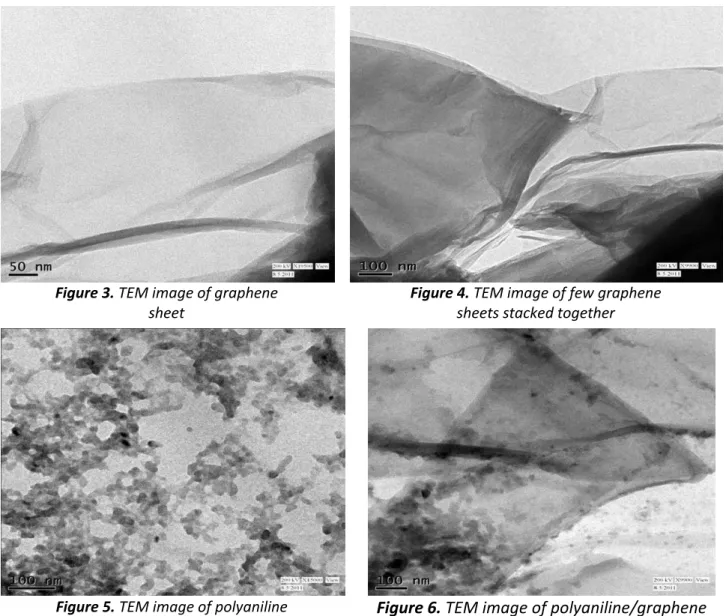
graphene contains very few organic groups. FT-IR peak in between 3500 to 3100 cm-1 is due to the absorbed moisture and the peak around 2200 cm-1 is due to atmospheric carbon dioxide often seen if the experiment is not done in nitrogen environment. There is a little hump around 1500 cm-1 because of C=C stretching in benzene ring of graphene. In the case of GO, due to oxidation there are several absorption bands corresponding to large number of chemical groups attached to the graphene sheets.
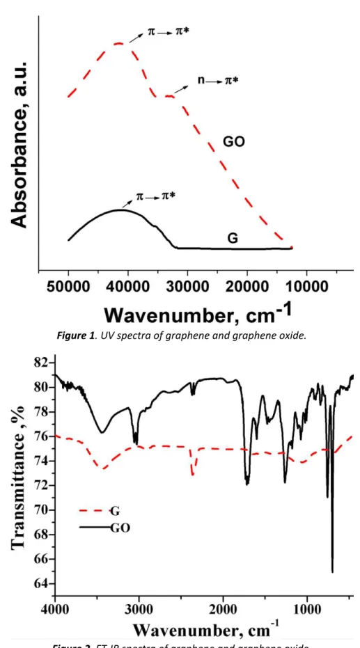
Figure 1. UV spectra of graphene and graphene oxide.
TEM Analysis
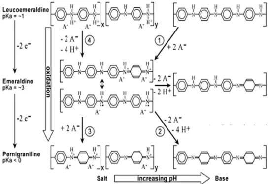
In TEM images the presence of single layer graphene (Figure 3) and multi layer graphene sheets stacked together (Figure 4) can be seen. From other TEM images (Figures 5 and 6) the formation of polyaniline particles (Figure 5) and polyaniline coating on graphene sheets (Figure 6) can also be detected. Graphite to graphene was routed through formation of graphene oxide followed by ultrasonication when different degree of delamination of original graphite occured. If the extent of delamination is very less, the original layered structure of graphite is almost retained. All these studies reveal that successful preparation of graphene from graphite can be achieved by the method described in experimental section.
Figure 3. TEM image of graphene
sheet
Figure 4. TEM image of few graphene
sheets stacked together
Figure 5. TEM image of polyaniline
particles
Figure 6. TEM image of polyaniline/graphene composite.
Cyclic voltammetry analysis
neat PANI and neat graphene as shown in the inset. The differences in qualitative and quantitative shape of CV curve for PANI and polyaniline/graphene composites have been attributed to the dispersion of PANI particles on graphene sheet which reduces the migration length of electrolyte ions during the charge-discharge process where graphene sheets provide an excellent path for the charge transfer [42]. Hence, the graphene increases the efficacy of PANI by providing a larger surface area and reducing the resistance to current flow.
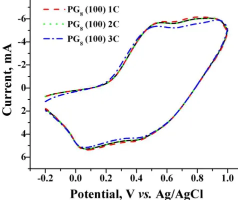
Scheme 1 Oxidation/reduction chemistry of polyaniline.
The stability of the composite has been checked by repeating the CV plots under the same condition for the same sample for several cycles [43]. Figure 8 shows the average particle size of graphite as received and the nano sized graphite with cumulative contribution in the total number of particles, %. The particle size analysis was done by Fritz particle size analyzer. The average particle size of graphite is 8 µ hile the parti le size of a o graphite as eyo d the ra ge of analyzer. Figure 9 shows that after 100, 200 and 300 CV cycles, at 0.08 V/s scan rate, the current-potential graphs almost superimposes on each other. This reveals the good electrochemical stability of the composite which is essential when it is used as a capacitor.
Figure 8. Particle size analysis of graphite and nano graphite
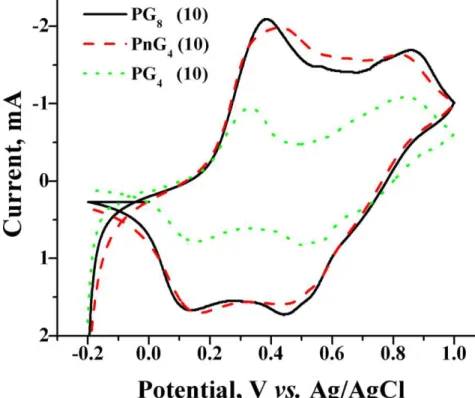
Both composition of PANI/graphene composite and size of graphene particles are expected to influence current-voltage characteristics of composites. Figure 10 compares the current potential behavior of polyaniline/graphene composite with variation in graphene weight percent and size of graphene sheet. It shows that with the addition of graphene the peaks in current - potential plots broaden in comparison to PANI. This is due to availability of alternate as well as low energy paths for charge transfer in PANI/graphene system through graphene. The presence of graphene in composite decreases the resistance of system hence there is an increase in the current and broadening of the peak. As shown in Figure 10 the resistance in PnG4 is almost equal to that of PG8 composite. This shows that with smaller size of graphene sheet the available surface area is higher and hence it leads to better utilization of PANI. Hence, this infers that with larger surface area the small scale graphene better decreases the resistance of the system and increases the capacitance of composite material by better utilization of PANI in composite. Figure 11 shows that with increase in the graphene weight percent there is no much increase in the current flow relatively to the neat PANI and in PANI/graphene composite as shown in Figure 7 [44]. It could also be seen that at lower scan rates (for example 0.01 V/s) different oxidation and reduction peaks could be distinguished but as the scan rate is increased, the peaks merged. This is due to the time constant effect in CV, since I=E/Rs (e-t/CdRs), where E is the potential step, Rs being the solution resistance, Cd, the double layer capacitance and t is time [45-46]. Here I decreases as the CdRs increases which
happens at a low scan rate. As the scan rate is increased CdRs does ’t gi e e ough ti e to the current to decrease hence distinct peaks are not observed.
Figure 10. Cyclic voltammogram of PG4, PG8 and PnG4 at 10 mV/s scan rate
Conclusions
the capacitance of the composite. In fact, with the reduction of the size of graphene sheet there is an increase in the capacitance value.
Acknowledgement: Authors would like to thank CSIR New Delhi for providing the fund to carry out this research work.
References
[1] R. Ramasubramaniam, J. Chen, H. Liu, Appl. Phys. Lett., 83 (2003) 2928–2930. [2] M. Rahaman, T. K. Chaki, D. Khastgir, J. Mater. Sci., 46 (2011) 3989–3999.
[3] W. J. Zou, S. S. Mo, S. L. Zhou, T. X. Zhou, N. N. Xia, D. S. Yuan, J. Electrochem. Sci. Eng. 1 (2011) 65–71.
[4] N. J. S. Sohi, M. Rahaman, D. Khastgir, Polym. Compos.,32 (2011) 1148–1154. [5] V. Panwar, R. M. Mehra, Polym. Eng. Sci., 48 (2008) 2178–2187.
[6] N. Syarif, I. A. Tribidasari, W. Wibowo, J. Electrochem. Sci. Eng. 3 (2013) 37–45. [7] X. Luo, D. D. L. Chung, Compos.: Part B, 30 (1999) 227–231.
[8] H. Kim, A.A. Abdala, C.W. Macosko, Macromolecules, 43 (2010) 6515–6530.
[9] T. Ramanathan, A.A. Abdala, S. Stankovich, D.A. Dikin, M. Herrera-Alonso, R.D. Piner, D.H.
Ada so , H.C. S h iepp, X. Che , R.S. Ruoff, S.T. Nguye , I. A. Aksay, R.K. Prud’ho e,
L.C. Brinson, Nat. Nanotech.,3 (2008) 327–331.
[10] Y.W. Zhu, S. Murali, W.W. Cai, X.S. Li, J.W. Suk, J.R. Potts, R.S. Ruoff, Adv. Mater.,22 (2010) 3906–3924.
[11] M.D. Stoller, S.J. Park, Y.W. Zhu, J.H. An, R.S. Ruoff, Nano Lett., 8 (2008) 3498–3502. [12] C. Lee, X. Wei, J.W. Kysar, J. Hone, Science,321 (2008) 385–388.
[13] X. Du, I. Skachko, A. Barker, E.Y. Andrei, Nat. Nanotech.,3 (2008) 491– 495.
[14] H.B. Zhang, W.G. Zheng, Q. Yan, Y. Yang, J.W. Wang, Z.H. Lu, G.Y. Ji, Z.Z. Yu, Polymer, 51 (2010) 1191–1196.
[15] A. Yu, P. Ramesh, X. Sun, E.M. Bekyarova, E. Itkis, R.C. Haddon, Adv. Mater.,20 (2008) 4740–4744.
[16] A.K. Geim, Science,324 (2009) 1530–1534. [17] D. Li, R. B. Kaner, Science,320 (2008) 1170–1168.
[18] A.G. Green, A.E. Woodhead, J. Chem. Soc.,1910 ‒ . [19] A. K. Sharma, Y. Sharma, J. Electrochem. Sci. Eng. 3 (2013) 47–56.
[20] M. Magioli, B. G. Soares, A. S. Sirqueira, M. Rahaman, D. Khastgir, J. Appl. Polym. Sci., 125 (2012) 1476–1485.
[21] M. Rahaman, L. Nayak, T. K. Chaki, D. Khastgir, Adv. Sci. Lett., 18 ‒ . [22] S. Bhadra, D. Khastgir, Polym. Test.,27 (2008) 851–857.
[23] S. Bhadra, S. Chattopadhyay, N.K. Singha, D. Khastgir, J. Appl. Polym. Sci.,108 (2008) 57–64. [24] M. Rahaman, T. K. Chaki, D. Khastgir, J. Appl. Polym. Sci., 128 ‒ .
[25] S. Bhadra, D. Khastgir, N.K. Singha, J.H. Lee, Prog. Polym. Sci.,34 (2009) 783–810. [26] J.C. Chiang, A.G. MacDiarmid, Synth. Met.,13 (1986) 193–205.
[27] W. Hualan, H. Qingli, Y. Xujie, L. Lude, W. Xin, Electrochem. Commun., 11 (2009) 1158– 1161.
[28] J.P. Zheng, P.J. Cygan, T.R. Jow, J. Electrochem. Soc.,142 (1995) 2699. [29] A.J. Burke, J. Power Sources,91 (2000) 37.
[30] B.E. Conway, Electrochemical Supercapacitors, Kluwer-Plenum, New York (1999). [31] S. Sopčić, M. Kraljić Roković, Z Mandić, J. Electrochem. Sci. Eng. 2 (2012) 41–52. [32] S. Chandra, et al., Chem. Phys. Lett.,519–520 (2012) 59–63.
[33] T. Nakajima, A. Mabuchi, R. Hagiwara, Carbon,26 (1988) 357–361.
[35] H. Dongxue, C. Ying, Colloid. Surf.,259 (2005) 179–187.
[36] V. Khomenko, E. Frackowiak, F. Beguin, Electrochimica Acta,50 (2005) 2499–2506. [37] Z. Hao, C. Gaoping, W. Weikun, Y. Keguo, X. Bin, Z. Wenfeng, C. Jie, Y. Yusheng,
Electrochimica Acta, 54 (2009) 1153–1159.
[38] H. Chi-Chang, L. Jeng-Yan, Electrochimica Acta, 47 (2002) 4055–4067. [39] R. Prakash, J. Appl. Polym. Sci.,83 (2002) 378–385.
[40] E.I. Santiago, E.C. Pereira, L.O.S. Bulhões, Synth. Met.,98 (1998) 87–93. [41] E. Smela, W. Lu, B.R. Mattes, Synth. Met., 151 (2005) 25–42.
[42] Y. Jun, W. Tong, S. Bo, F. Zhuangjun, Q. Weizhong, Z. Milin, W. Fei, Carbon, 48 (2010) 487– 493.
[43] Z. Lu, Z. Liang, X. Yuxi, Q. Tengfei, Z. Linjie, S. Gaoquan, Electrochimica Acta, 55 (2009) 491– 497.
[44] Y. Li, H. Peng, G. Li, Kezheng Chen, Eur. Polym. J., 48 (2012) 1406–1412. [45] Y.G. Wang, H.Q. Li, Y.Y. Xia, Adv. Mater., 18 (2006) 2619–2623.
[46] J. B. Allen, R.F. Larry, 2nd addition, Electrochemical Methods: Fundamentals and Applications, John Wiley (2001).
© 13 by the authors; licensee IAPC, Zagreb, Croatia. This article is an open-access article distributed under the terms and conditions of the Creative Commons Attribution license
