*e-mail: [email protected]
1. Introduction
The continuous search for new materials that combine high performance and easy conformation (manufacture) has been the focus of a large number of studies in recent decades. Composite materials and reinforced plastics have been important in these investigations, given that they meet these requirements as well as their added advantage of being low weight, an indispensable parameter in numerous structural applications.
Glass iber reinforced plastics (GFRP) are among the most widely used because of their varied properties and low iber cost when compared with other synthetic ibers such as carbon and aramid.
Fracture characteristics of composite materials are strongly inluenced by the properties of their components, such as type of reinforcement and matrix, proportion of these components and most importantly iber distribution and orientation (anisotropy)1. Anisotropy becomes a limiting factor when applying composite materials as laminar structure.
In addition to this complexity, the application of these elements may also exhibit sharp differences in the cross-sectional area, such as holes and notches. These types of geometric discontinuities are often necessary to establish links between structural project mechanisms and may generate serious problems in the distribution of internal stresses to the structural element, originating “stress concentration areas”2-6. This phenomenon has a direct inluence on inal fracture, since it concentrates the fracture region in the geometric discontinuity section, primarily in polymer composites composed of a material considered “brittle”7.
The effect of stress concentration becomes much more complex in composite materials, since it does not depend only on geometry and type of loading, as in conventional materials8,9. For this reason, some theoretical and experimental models have been seeking to quantify it based on the damage zone, that is, the inal fracture region10.
Based on this, many works have been developed involving experimental and numerical analysis in order to quantify the phenomenon of stress concentration in composites through mainly theories of failure like point stress criterion (PSC) and average stress criterion (ASC)10-12. Highlight can be made that these analyzes are mostly made of composite materials reinforced only with synthetic ibers like carbon; hence, the importance of models also applied to GFRP used in composite structures.
This study investigates the inluence of central holes in the longitudinal area (with a reduced cross-sectional area) on fracture characteristics of two composite laminates, under uniaxial tensile loading. The conigurations of these laminates are deined as a composite laminate based only on E-glass (ML) iber mats (short) with seven layers, whereas the other laminate is composed of bidirectional fabric of the same type of iber (FL) and 4 layers. The inluence of anisotropy is studied for the case of the FL
composite, where different iber orientations are observed in its layers in relation to the direction of the applied load. Fiber orientations in composites are deined as FL ±45º composite and FL 0/90º composite.
Fiber orientation in their layers (coniguration) with respect to applied load direction may simultaneously inluence the previously mentioned properties13.
To make it easier to understand the properties under study, composites were deined as ML and FL for the case
Fracture Characteristics and Anisotropy in Notched Glass Fiber Reinforced Plastics
Sérgio Renan Lopes Tinôa,b*, Eve Maria Freire de Aquinoa
aPrograma de Pós-graduação em Engenharia Mecânica, Universidade Federal do Rio Grande do Norte – UFRN, Campus Universitário-Centro de Tecnologia, Lagoa Nova, Natal, RN, Brazil
bInstituto Federal de Goiás – IFG, Luziânia, GO, Brazil
Received: June 12, 2014 – Revised: November 30, 2014
The damage mechanism of reinforced plastics may be present in many different ways, since it depends on many factors. Highlights may be given to the effect of stress concentration in of geometric discontinuity in the sections of these structural elements, which in general always leads to certain characteristics of the fracture. In the case of glass iber reinforced plastics (GFRP) it is expected the same tendency, beyond the inluence of reinforcement and its internal orientation in the layers (anisotropy). The aims of this work are detailed study of the inluence of the holes (longituninal section) in the characteristic fracture in GFRP submitted to tensile loading. Three different conigurations of composite laminates were studied: two reinforced with Eglassiber bidirectional textil fabric and the other only with short mats, also Eglassiber. The results showed the inluence of all parameters listed above in the inal fracture characteristics and residual properties.
of composites without a central hole, while HML and HFL refer to composites with central hole.
Finally, microscopic analyses of final fracture characteristics were conducted to understand the effect of hole in the composite section on inal fracture. Analyses were carried out using optical microscopy.
In this work, the phenomenon of stress concentration was studied, considering that the alterations suffered in relation to the laminates strength have as basis the Residual Strength-RS calculation, experimentally, using the concepts determined by14.
2. Material and Methods
The hand layup process was used to manufacture the composite laminates, which were fabricated by Tecniplas Nordeste Indústria e Comércio Ltda in the form of two 1.0 m2 plates. The raw materials used were orthophthalic
polyester resin (Novapol L120) as matrix and E-glass ibers as reinforcement. One plate was deined as a composite laminate of short E-glass iber mats (450 g/m2) denominated
ML. The other plate was an E-glass fiber reinforced composite laminate with bidirectional fabric (600 g/m2)
designated FL. The ML plate was manufactured with seven layers and mean thickness of 5.0 mm, while the FL plate was built with only four layers and mean thickness of 3.7 mm.
The reason for choosing a smaller number of layers for the FL composite is due to an ASTM D5766-0714 standard testing method requirement, stating that it is advisable to use a hole diameter (6.0 mm)/laminate thickness ratio between
1.5 and 3.0. For the ML composite, the choice was based on the fact that this number of layers is traditionally used in industry, primarily in the manufacture of medium-sized reservoirs.
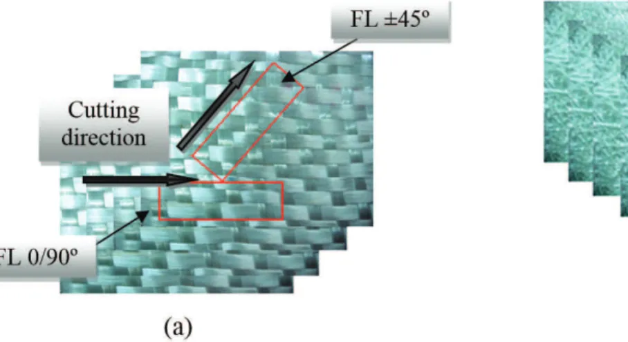
In the case of the FL composite, two conigurations with
different iber layer orientations with respect to applied load direction were created: FL 0/90º and FL ±45º. It is important to underscore that for both FL composites the same plate was used to obtain test specimens and that the orientation of the ±45º and 0/90º iber occurred as a function of cut
direction, resulting in the anisotropy effect.
Test specimens destined for hole geometries were HML, HFL 0/90º and HFL ±45º. Holes were made by enlarging an initial 2.0 mm pre-hole to the standard diameter14 of 6.0 mm. Diamond thread drills were used to avoid possible irregularities on the hole surface. Delaminations and microcracks after drilling were not observed through macroscopic and microscopic analyzes. After appropriate test specimen dimensions were obtained, the regions where the cut was applied were smoothed and polished.
Figure 1 shows the test specimen cutting scheme for the FL and ML conigurations.
The uniaxial tensile test was performed to ind the tensile strength and Young’s modulus (in the direction of load application) of the laminate under several conditions of study. Therefore, eight specimens for each condition were confectioned, obtaining ive tests considered as valid according to the technical standard. Displacement velocity in uniaxial tensile testing was 1.0 mm/min (standard) for all test specimens. All tests were carried out at ambient temperature using a mechanical universal testing machine (Shimadzu AGI-250 KN) with maximum capacity of 25 T.
Dimensions of test specimens without a hole were deined by ASTM D 3039-0815, while for those with a hole ASTM D 5766- 0714 was used. All specimens had a useful length (gage) of 127 mm and widths of 36 mm (HML, HFL 0/90º, HFL ±45º) and 25 mm (ML, FL 0/90º, FL ±45º). All test specimen dimensions were within the standard tolerance of ±1%.
The experimental Residual Strength (RS), according to14,16, for all conigurations studied was calculated from the Equation 1:
N
UN
RS = σ
σ (1)
Considering that σN is the tensile strength found in the
tests with the hole (notched strength) and σUN is the tensile
strength found in the tests without the hole (unnotched strength). It is highlighted that all parameters mentioned were calculated in the largest cross-sectional area of the specimens, according to the standard.
Microscopic and macroscopic analyses in the fracture region of the test specimens were conducted to study inal fracture characteristics (pre-fractured specimens). An Olympus MG optical microscope was used for microscopic analysis.
3. Results and Discussion
3.1. Uniaxial Tensile Tests – notched and
unnotched specimens
With regard to the uniaxial tensile test for especimens without hole (ML, FL 0/90º, FL ±45º) and with hole (HML, HFL 0/90º, HFL ±45º) the mean values obtained for ultimate tensile strength are shown in Table 1, as well as their respective dispersions.
It is noteworthy that the dispersions refer to the absolute difference between the maximum and minimum values obtained in the test for each parameter analyzed. It is also worth pointing out that for all the conigurations. Dispersion percentages, in general, are within levels speciic to polymer composites only based on glass ibers16.
To determine ultimate tensile strength in each specimen with hole was determined by the maximum tension developed in the laminate is determined in the largest area of the cross section and not in the section where the stress concentration phenomenon occurs. This is because a study based on this phenomenon requires calculation of the stress concentration factor (K) to determine maximum stress, which requires methodology and technical tests or speciic experiments.
The results obtained for RS were: 0.7 for ML, 0.82 for FL 0/90°, and 0.89 for FL ±45º, respectively. The Figure 2 shows better the values.
Overall, the loss of strength for FL ±45º was much less than for the others (only 11.43%), but even so, it should be a value to consider with respect to structural projects, since the hole had a negative inluence on inal mechanical response. Another factor that can inluence behavior is the strong presence of shear overlapping that of traction due to the orientation of the ibers against the loading direction. It is worth noting that this behavior is typical of a composite considered orthotropic with reinforcement at 45° in relation to the load application17.
Regardless of coniguration, in all cases, the hole had a negative inluence with respect to ultimate strength. Note that for ML, this inluence was more pronounced than for
FL coniguration, demonstrating that this is more relevant in isotropic materials.
The FL 0/90º configuration displayed superior mechanical behavior in relation to the others, which was
expected considering the reinforcement type (bidirectional fabric) and the fiber direction with respect to load application. However, the smallest percentage difference between ultimate tensile strengths (11%), only considering the hole, was found for the laminate at ± 45°.
3.2. Fracture analysis of conigurations without
hole
Figure 3 shows some of the post-test specimens of the ML. Damage was concentrated in the inal fracture region,
with no signiicant variations observed in other areas. According to ASTM D 3039-0815, LGM (Lateral Gage Middle) was the type of fracture observed, which is perfectly valid for the test.
The fragile fracture in the ML exhibited maximum deformation of 4% of inal fracture. Figure 4a depicts an optical micrograph of a region near the inal fracture, showing cracks spreading through the iberglass layers.
Figure 4b shows that cracks initially spread perpendicularly to load direction, then become intralaminar split spreading in the direction of the applied load (longitudinally). It was also observed that when cracks spread longitudinally they caused a “rupture or non-adhesion” on the fiber/matrix interface, characterizing adhesive fracture.
Cracks that spread only in the matrix are called cohesive matrix fractures and those that cross ibers longitudinally are known as cohesive iber fractures (Figure 4b).
The ML configuration showed no interlayer delamination, which was expected since it is composed only of iberglass mats, causing little discrepancy between interlaminar stresses.
Fractures in the FL 0/90º coniguration initiated with progressive cracking perpendicular to load application,
Table 1. Tensile strength (mean values) and respective dispersions.
Specimen Tensile Strength (MPa) Specimen Tensile Strength (MPa)
ML 90.13 HML 62.74
Dispersion (%) 7.47 Dispersion (%) 11.71
FL 0/90º 186.59 HFL 0/90º 152.99
Dispersion (%) 15.13 Dispersion (%) 20.77
FL ±45º 76.14 HFL ±45º 67.44
spreading along the entire length of the test specimen (Figure 5), exhibiting a state of saturation before the inal fracture. They also displayed iber pull-out phenomenon in the inal fracture region, characteristic damage in fabric-based polymer composites. This iber pull-out becomes noticeable after test specimens are removed from the machine clamps.
Figure 6 shows the inal fracture region of the FL 0/90º, which according to ASTM D 3039-0815, is the LGM mode and therefore valid for this type of test.
In addition to matrix cracking, microscopic fracture analysis revealed adhesive fractures, delamination and iber pull-out.
Optical microscopy showed that delaminations occur when transverse cracks in the matrix spread to the interface between composite laminate layers (Figure 7a). The adhesive fracture (non-adhesion to the iber/matrix interface) is shown in Figure 7b.
Despite the existence of manufacturing defects in the composite, Figure 7b, they caused no damage during loading, even though an adhesive fracture was observed very close to them, but in a region without any apparent damage.
Fracture characteristics of the FL ±45º were similar to those of the FL 0/90º coniguration, that is, cracking in the entire matrix occurs progressively, exhibiting a saturation state before final fracture (Figure 8). Being a
fabric-reinforced composite, it also displayed the iber pull-out phenomenon, Figure 8, although less intense than the FL 0/90º. According to ASTM D 3039-0815 an LGM fracture was also observed in the coniguration.
Microscopic fracture analysis of this coniguration showed no interlayer delaminations. All cracks occurred at
45º(Figure 9), in the direction of shear and iber orientation.
Figure 3. Post-test specimens of the ML coniguration.
Figure 4. (a) Region near inal fracture, (b) cohesive and adhesive fracture near inal fracture region – Uniaxial tensile of ML coniguration.
As cracks spread they gave rise to adhesive and cohesive fractures (matrix and ibers), as well as splits between strand intersections.
An important characteristic of this coniguration was the presence along the entire length of the test specimens of split in the strand intersections region due to strong shearing that occurs in the reinforcement direction at 45º. Figure 10 demonstrates the effect of this strand intersections fragility owing to longitudinal and interlaminar splits. It was also observed that adhesive fractures in the iber/matrix interface and cohesive fractures in the iber and matrix originate in these splits.
Figure 6. Final fracture characteristics of the FL 0/90º coniguration.
Figure 7. (a) Fracture characteristics, (b) adhesive iber fracture and manufacturing defect. FL 0/90º coniguration.
Figure 8. Macroscopic fracture analysis the FL ±45º coniguration.
3.3. Fracture analysis for conigurations with
hole
Macroscopic analysis of inal fracture characteristics for the HML coniguration showed localized damage, which was expected due to the type of reinforcement used (randomly distributed short iber mats).
This fracture is classiied as LGM and is valid only if it is located in the hole section, owing to the stress concentration effect that occurs there. Figure 11 shows inal fracture characteristics of the HML coniguration after the uniaxial tensile test.
This type of coniguration can be considered to have macroscopically isotropic behavior in relation to elastic properties (characteristic of deformation). Damage that occurred in the HML was concentrated in the cross-section where the hole is located, according to ASTM D 5766-0714 standard testing. Figure 12 shows a micrograph of the inal fracture region of the HML, where a very high concentration of cracks can be observed in the matrix along with the presence of splits.
The macroscopic study of inal fracture characteristics for the HFL 0/90º shows damage that initiates with matrix cracks, transverse to the applied load, which spread progressively along the entire length of the test specimen, exhibiting saturation state before inal fracture.
Thus, as with the HML coniguration, the inal fracture (LGM mode) in the HFL 0/90º coniguration occurs in the hole section, as foreseen in the standard.
Figure 13 depicts the test specimen after uniaxial tensile testing of the HFL 0/90º. Macroscopic analysis of fracture
characteristics shows the iber pull-out phenomenon, typical of fabric-reinforced composites7.
It is also important to note that the presence of a hole in the coniguration did not signiicantly alter inal fracture behavior when compared to the FL 0/90º. However, as shown in Figure 14, the inal fracture region is saturated in the matrix, underscoring that these transverse cracks are more intense in the hole region, characterizing the stress concentration phenomenon. Microscopic analysis of the
HFL 0/90º coniguration shows high concentration of splits
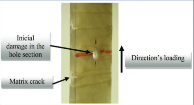
in the inal fracture region of the matrix (Figure 15). Figure 16 shows a test specimen during uniaxial tensile testing of the HFL ±45º coniguration, in which cracks initially form in the hole section, where stresses are concentrated.
Macroscopic analysis of inal fracture characteristics for the HFL ±45º also shows damage initiating with matrix Figure 10. Splits, adhesive and cohesive fractures in the FL ±45º coniguration.
Figure 11. Post-test inal fracture characteristics – HML coniguration.
Final fracture of the HFL ±45º coniguration (LGM mode) was concentrated in the hole section, in accordance with the standard, that is, lateral in the middle of the gage, which is perfectly valid for this test (Figure 17).
Figure 17 shows inal fracture characteristics in the hole section for the HFL ±45º. Fiber pull-out was also observed in all bidirectional fabric reinforced composites studied here.
With respect to microscopic analysis, Figure18 shows that, in addition to reaching the reinforcement layer (intralaminar crack), initial cracking provoked matrix cracks that spread at approximately 45º, following iber
orientation.
Another aspect to consider is the fact that FL ±45˚ displays less intense damage, principally in matrix cracking, when compared to FL 0/90º. This fracture characteristic prevailed in the two cases, i.e., with and without hole. The shear stresses for the FL ±45˚ have direct inluence on the
inal damage and residual strength.
3.4. Comparison of fracture characteristics for
the conigurations analyzed
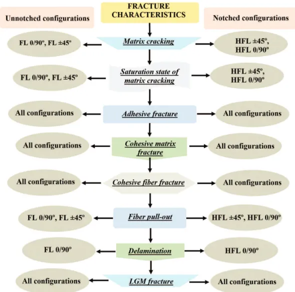
Figure 19 shows fracture characteristics observed in the conigurations under study, with the aim of determining the inluence of the hole and/or anisotropy existing in the composites.
The presence of a center hole in the conigurations analyzed did not significantly change final fracture characteristics, but rather how it spread along the entire length of the test specimens. In the case of test specimens with geometric discontinuity, fractures were concentrated in the region near the hole, where matrix cracks were spaced closer together due to the effect of stress concentration.
With respect to the conigurations used, there were significant differences when all the composites were compared, given that iber pull-out was only observed in composites with anisotropy. Delamination, another fracture characteristic, was observed only in the FL 0/90º
coniguration.
The presence of elements that can concentrate stress in composite materials must be considered in any configuration and independently of its degree of anisotropy, although18 considers that for discontinuous pre-impregnated carbon/epoxy, stress concentration occurs due to heterogeneity of the material (in relation to reinforcement distribution) and not because of the existence of a circular hole and that, therefore, considers the material insensitive to the notch.
Figure 13. Final fracture region - HFL 0/90º coniguration.
Figure 14. Matrix cracks in the HFL 0/90º coniguration.
Figure 15. Splits in the matrix. HFL 0/90º coniguration.
Figure 16. Initial damage in the hole section - HFL ±45º
coniguration.
Figure 17. Fiber pull-out phenomenon in the HFL ±45º coniguration.
Figure 18. Matrix cracks in the reinforcement direction - HFL ±45º coniguration.
4. Conclusions
The following conclusions can be drawn from the study results:
- Experimental Residual Strength showed the inluence of the material configuration, the largest being observed for FL ± 45º.
- For the uniaxial tensile test, the hole had a negative inluence on the mechanical properties of strength, i.e., load support of the material. This behavior is based on tensile strength losses of 30%, 18%, and 11%
for the ML, FL 0/90º, and FL ±45º conigurations, respectively.
- For the configurations studied the presence of anisotropy and existence of continuous ibers in the loading direction alleviate the loss of tensile strength with hole in its longitudinal section (with reduction of the cross section), since the greatest loss was recorded for ML.
- ML, HML, FL 0/90º, HFL 0/90º, FL ±45º and HFL ±45º conigurations fractures generally exhibited
LGM mode inal fracture;
- Micrographic fracture analysis showed the presence of cohesive matrix and iber fractures and adhesive (fiber/matrix interface) fractures in the other composites studied, since delaminations
(non-adhesion between laminate layers) occurred only in FL 0/90º and HFL 0/90º;
- With regard to fracture behavior of the laminates under study, intense cracking was observed in the matrix along the entire length of the test specimen only in bidirectional fabric-reinforced composites, with characteristics peculiar to the composite at ±45º, where cracking occurred in the reinforcement direction due to shear forces in the direction of the reinforcement used;
- Matrix saturation occurs only in iberglass fabric-based composites, irrespective of a hole, but is more concentrated in the hole section, owing to the effect of stress concentration;
- The pull-out phenomenon was recorded only in the iberglass fabric-based composite (anisotropic); - In general form, the comparative study of fracture
characteristics shows that the presence of a hole was more signiicant for anisotropic composites (FL 0/90º and FL ±45º conigurations), giving rise to a more intense fracture process.
Acknowledgements
The authors acknowledge the inancial support provided by CNPq.
References
1. Herakovich CT. Mechanics of ibrous composites. New York: Ed. Wiley; 1997. 460 p.
2. Zhao JH, Wang XF, Dharani LR and Wei J. Notch stress
concentrations and failure characteristics in laminates with triple parallel notches. Composites Science and Technology.
2000; 60(15):2865-2872.
http://dx.doi.org/10.1016/S0266-3538(00)00161-5.
3. Yan F and Pitchumani R. Effects of interphase formation on
the modulus and stress concentration factor of fiber-reinforced thermosetting-matrix composites. Composites Science and Technology. 2004; 64(10-11):1437-1452. http://dx.doi. org/10.1016/j.compscitech.2003.09.027.
4. Toubal L, Karama M and Lorrain B. Stress concentration
in a circular hole in composite plate. Composite Structures. 2005; 68(1):31-36. http://dx.doi.org/10.1016/j. compstruct.2004.02.016.
5. Pihtili H. Calculation and Comparison of Stress Concentration Factors in Composite Inverted-tooth Chain Link Plates
with Various Dimensions. Journal of Reinforced Plastics and Composites. 2008; 27(18):1953-1962. http://dx.doi. org/10.1177/0731684407087584.
6. Hufner DR and Accorsi ML. A progressive failure theory
for woven polymer-based composites subjected to dynamic loading. Composite Structures. 2009; 89(2):177-185. http:// dx.doi.org/10.1016/j.compstruct.2008.07.023.
7. Aquino EMF and Tinô SRL. Descontinuidade Geométrica nos Compósitos Poliméricos: Resposta Mecânica e Característica da Fratura. In: Proceedings of the IX Congreso Iberoamericano de Ingeniería Mecánica - CIBIM; 2009. Las Palmas de Gran
Canaria Anais; 2009. v. 1. p. 12/2-12/9.
8. Awerbuch J and Madhukar MS. Notched strength of composite laminates: Predictions and experiments – A review. Journal of
Reinforced Plastics and Composites. 1985; 4(1):3-159. http:// dx.doi.org/10.1177/073168448500400102.
9. Nuismer RJ and Whitney JM. Uniaxial Failure of Composite Laminates Containing Stress Concentration, in Fracture Mechanics of Composites, ASTM STP 593. Philadelphia:
ASTM; 1975. p. 117-142.
10. Shin CS and Wang CM. An Improved Cohesive Zone Model for Residual Notched Strength Prediction of Composite Laminates with Different Orthotropic Lay-ups. Journal of Composite Materials. 2004; 38(9):713-736. http://dx.doi. org/10.1177/0021998304031635.
11. Hallett SR, Green BG, Jiang WG and Wisnom MR. An
experimental and numerical investigation into the damage mechanisms in notched composites. Composites. Part A, Applied Science and Manufacturing. 2009; 40(5):613-624. http://dx.doi.org/10.1016/j.compositesa.2009.02.021.
12. Mollenhauer D, Iarve EV, Kim R and Langley B. Examination
of ply cracking in composite laminates with open holes: a
Moire´ interferometric and numerical study. Composites. Part A, Applied Science and Manufacturing. 2006; 37(2):282-294. http://dx.doi.org/10.1016/j.compositesa.2005.06.004.
13. Yeh HY and Rashid HN. Effect of t-stress on damage zone
size predictions of notched laminated composites. Journal of Reinforced Plastics and Composites. 2006; 25(1):89-98. http:// dx.doi.org/10.1177/0731684406055458.
14. American Society for Testing and Materials – ASTM. D 5766-07: Standard Test Method for Open Hole Tensile Strength of Polymer Matrix Composite Laminates. West Conshohocken; 2007.
16. Tinô SRL, Fontes RS and Aquino EMF. Theories of failure
average stress criterion and point stress criterion in notched fiber-reinforced plastic. Journal of Composites Materials. 2013. http://dx.doi.org/10.1177/0021998313501920.
17. Hufner DR and Accorsi ML. A progressive failure theory
for woven polymer-based composites subjected to dynamic
loading. Composite Structures. 2009; 89(2):177-185. http:// dx.doi.org/10.1016/j.compstruct.2008.07.023.
18. Feraboli P, Peitso E, Cleveland T, Stickler PB and Halpin JC. Notched behavior of prepreg-based discontinuous carbon