Numerical and experimental analysis of the behavior of
structural elements composed of double lattice panels
i lled with cast-in-place concrete
Análise numérica e experimental do comportamento de
elementos estruturais compostos por painéis duplos
treliçados preenchidos com concreto moldado no local
a Universidade Federal de Uberlândia, Faculdade de Engenharia Civil, Uberlândia, MG, Brasil.
Received: 25 Feb 2015 • Accepted: 22 May 2015 • Available Online: 7 Aug 2015
Abstract
Resumo
An experimental and numerical investigation was conducted into the factors that interfere in the shear strength of the concrete-concrete interface in structures composed of double lattice panels subjected to direct shear stress. The experimental program consisted of testing 26 direct shear models with varying widths of concrete i lling of 7 cm, 9 cm and 13 cm, with smooth and rough interfaces, as well as dif erent concrete compressive strengths in the i lled region. The numerical modeling, which was performed with ANSYS software, employed solid i nite elements, bar elements and contact elements, taking into account the non-linearity of the materials involved. The analyses of the experimental results under direct shear indicated that the transfer of stresses at the interface occurred with loss of adhesion. The numerical simulations indicated that the higher the geo-metric ratio of reinforcement the higher the direct shear strength of the structural model. In general, the slip of the models with smooth interfaces was 2 or 3 times greater than the models with rough surfaces. Numerically, the models with smooth interfaces showed a 36.61% gain in shear strength when the compressive strength in the region i lled with concrete increased from 20 MPa to 28.4 MPa.
Keywords: numerical modeling, experimental analysis, double panels lattice, direct shear, nonlinear analysis.
Este estudo apresenta uma investigação experimental e numérica dos fatores que interferem na resistência ao cisalhamento da interface entre concretos de estruturas formadas por painéis duplos treliçados, submetidos ao cisalhamento direto. O programa experimental foi realizado por meio do ensaio de 26 modelos submetidos ao cisalhamento direto, com a largura do concreto de preenchimento variando de 7 cm, 9 cm e 13 cm, com interfaces lisas e rugosas, além de diferentes resistências à compressão do concreto na região de preenchimento. A modelagem numérica foi feita com a utilização do software ANSYS e consistiu no emprego de elementos i nitos sólidos, elementos de barras e elementos de contato, levando-se em conta a não linearidade física dos materiais envolvidos. A análise dos resultados experimentais mostra que, sob cisalhamento di-reto, a transferência de tensões na interface ocorre com perda de adesão. A simulação numérica indica que quanto maior a taxa de armadura que cruza a interface maior é a resistência ao cisalhamento direto. Em geral, o deslizamento relativo observado nos modelos com interface lisa é em torno de 2 a 3 vezes maior que nos modelos com interface rugosa. Numericamente, observa-se um ganho na resistência cisalhante de 36,61% ao elevar a resistência à compressão na região de preenchimento do concreto de 20 MPa para 28,4 MPa, para os modelos de interfaces lisas. Palavras-chave: modelagem numérica, análise experimental, painel duplo treliçado, cisalhamento direto, análise não linear.
B. M. LACERDA a
M. C. V. LIMA a [email protected]
F. A. R. GESUALDO a [email protected]
V. C. CASTILHO a [email protected]
UNREVISED GALLEY PR
UNREVISED GALLEY PR
OOF
UNREVISED GALLEY PR
UNREVISED GALLEY PR
UNREVISED GALLEY PR
was conducted into the factors that interfere
was conducted into the factors that interfere
subjected to direct shear stress.
subjected to direct shear stress.
models with varying widths of concrete i lling of 7 cm, 9 cm and 13 cm, with smooth and rough interfaces, as well as dif erent concrete compressive models with varying widths of concrete i lling of 7 cm, 9 cm and 13 cm, with smooth and rough interfaces, as well as dif erent concrete compressive strengths in the i lled region. The numerical modeling, which was performed with ANSYS software, employed solid i nite elements, bar elements strengths in the i lled region. The numerical modeling, which was performed with ANSYS software, employed solid i nite elements, bar elements and contact elements, taking into account the non-linearity of the materials involved. The analyses of the experimental results under direct shear and contact elements, taking into account the non-linearity of the materials involved. The analyses of the experimental results under direct shear
that the transfer of stresses at the interface occurred
that the transfer of stresses at the interface occurred
metric ratio of reinforcement the higher the direct shear strength of the structural model. In general, the slip of the models with smooth interfaces metric ratio of reinforcement the higher the direct shear strength of the structural model. In general, the slip of the models with smooth interfaces was 2 or 3 times greater than the models with rough surfaces. Numerically, the models with smooth interfaces showed a 36.61% gain in shear was 2 or 3 times greater than the models with rough surfaces. Numerically, the models with smooth interfaces showed a 36.61% gain in shear strength when the compressive strength in the region i lled with concrete increased from 20 MPa to 28.4 MPa.
strength when the compressive strength in the region i lled with concrete increased from 20 MPa to 28.4 MPa. : numerical modeling, experimental analysis, double panels lattice, direct shear, nonlinear analysis. : numerical modeling, experimental analysis, double panels lattice, direct shear, nonlinear analysis.
Este estudo apresenta uma investigação experimental
Este estudo apresenta uma investigação experimental
concretos de estruturas formadas por painéis duplos treliçados, submetidos ao cisalhamento direto. O programa experimental foi realizado por concretos de estruturas formadas por painéis duplos treliçados, submetidos ao cisalhamento direto. O programa experimental foi realizado por meio do ensaio de 26 modelos submetidos ao cisalhamento direto, com a largura do concreto de preenchimento variando de 7 cm, 9 cm e 13 cm, meio do ensaio de 26 modelos submetidos ao cisalhamento direto, com a largura do concreto de preenchimento variando de 7 cm, 9 cm e 13 cm, com interfaces lisas e rugosas, além de diferentes resistências à compressão do concreto na região de preenchimento. A modelagem numérica com interfaces lisas e rugosas, além de diferentes resistências à compressão do concreto na região de preenchimento. A modelagem numérica foi feita com a utilização do software ANSYS e consistiu no emprego de elementos i nitos sólidos, elementos de barras e elementos de contato, foi feita com a utilização do software ANSYS e consistiu no emprego de elementos i nitos sólidos, elementos de barras e elementos de contato, levando-se em conta a não linearidade física dos materiais envolvidos. A análise dos resultados experimentais mostra que, sob cisalhamento levando-se em conta a não linearidade física dos materiais envolvidos. A análise dos resultados experimentais mostra que, sob cisalhamento
di-UNREVISED GALLEY PR
reto, a transferência de tensões na interface ocorre com perda de adesão. A simulação numérica indica que quanto maior a taxa de armadura que reto, a transferência de tensões na interface ocorre com perda de adesão. A simulação numérica indica que quanto maior a taxa de armadura que cruza a interface maior é a resistência ao cisalhamento direto. Em geral, o deslizamento relativo observado nos modelos com interface lisa é em cruza a interface maior é a resistência ao cisalhamento direto. Em geral, o deslizamento relativo observado nos modelos com interface lisa é em torno de 2 a 3 vezes maior que nos modelos com interface rugosa. Numericamente, observa-se um ganho na resistência cisalhante de 36,61% torno de 2 a 3 vezes maior que nos modelos com interface rugosa. Numericamente, observa-se um ganho na resistência cisalhante de 36,61% ao elevar a resistência à compressão na região de preenchimento do concreto de 20 MPa para 28,4 MPa, para os modelos de interfaces lisas. ao elevar a resistência à compressão na região de preenchimento do concreto de 20 MPa para 28,4 MPa, para os modelos de interfaces lisas.
UNREVISED GALLEY PR
Palavras-chave:
Palavras-chave:
B. M. LACERDA
1. Introduction
Partial cross-section precast concrete structural elements have been employed in Brazil for the construction of small buildings, as a rational approach for using prefabricated components.
The Brazilian technical standard ABNT NBR 9062:2006 deines parts composed of partial cross-sections as concrete elements in-terconnected by separate forming systems, which act as a single part subjected to the loads imposed upon it after its solidiication. Partial cross-section parts are used because they reduce the con-sumption of formwork and shoring and are an option for lower weight elements for small and medium-sized applications, which can be transported during their assembly.
The technical literature describes investigations of the shear trans-fer mechanism across new and existing concrete interfaces by many authors, e.g., Hofbeck, Ibrahim and Mattock (1969); Hsu, Mau and Chen (1987); Bass, Carrasquillo and Jirsa (1989), Araújo (1997, 2002) and Kabir (2005).The structural behavior of precast concrete sandwich panels has also been studied both experimen-tally and theoretically, as presented by Benayoune et al. (2008). According to the ABNT NBR 6118:2014 standard, requirements that ensure the quality and structural strength, service perfor-mance and durability of concrete structures must be met during the construction and service stages.
In this context, this study aims to examine the structural behav-ior of precast concrete double lattice panels by means of numeri-cal modeling and experimental analysis. The aim is to determine whether these components behave monolithically under direct shear. The interface bonds in concrete with diferent ages should be evaluated, once the mechanical behavior of the precast ele-ment is inluenced by shear load transfer at the interface.
The structural response at the interface of the double lattice panel illed with cast-in-place concrete (CPC) is assessed taking into account the efect of variations in the width of iller concrete, the
compressive strength of the concrete, and the surface roughness of the bonding interface.
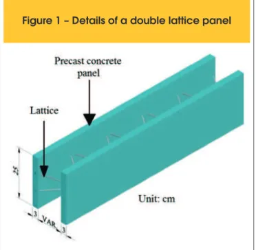
2. Double lattice panels
The double lattice panel consists of two precast concrete (PCC) plates about 3 cm to 3.5 cm thick and about 25 cm high. The plates are interconnected by means of an electro-welded lattice frame, with the distance between the plates varying according to the de-sign requirement (Figure 1).
Some of the advantages of using this structural system at con-struction sites, according to El Debs (2000), are: faster produc-tion; lower consumption of concrete; lower expenses with riggers and carpenters, since the panel serves as formwork; substantial reduction in timber and scafolding; and reduction of wastes gener-ated during the construction phase, which ensures greater savings in construction site cleaning costs. In the case of precast partial cross-sections – the focus of this work, double lattice panels are an option for the use of the technique, preserving the overall char-acteristics of monolithic concrete structures.
However, structural elements composed of double lattice panels are limited in terms of shape, e.g., curved parts, and size, because they are built by hand; hence, a heavier component would make the construction process very diicult.
Double lattice panels are bonded with cast-in-place concrete, be-cause this bond is simple to make.
According to Araújo (2002), the behavior of these interface bonds in concrete should be evaluated, because the fact that they have diferent ages and characteristics can inluence their mechanical behavior, such as shear load transfer at the interface.
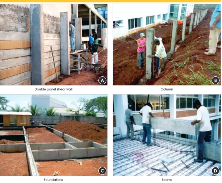
Precast panels are manufactured with ixed thicknesses, but their dimensions of height and width vary, and these panels can be used in various applications (Figure 2).
Each side of a double panel is concreted at an interval of 24 hours. After solidiication, the structural behavior is inluenced by shear load transfer at the interface. Solidiication of the double lattice panel may lead to diferential shrinkage and creep in the precast concrete (PCC) and cast-in-place concrete (CPC), since their ages and characteristics difer. Adherence between contact surfaces is an important parameter to be investigated, because it inluences the transfer of shear stresses at the interface.
3. Shear transfer mechanisms between
concrete surfaces
Shear transfer at the interface between diferent ages concrete can be divided into transfer through the contact surface and through the reinforcement transverse to this surface.
Shear load transfer at the contact surface between two concrete elements occurs by bonding and can be divided into:
n Adhesion: this is the irst mechanism that is triggered at the
interface between concrete components and is limited to low shear stress once it is removed by slip.
n Friction: after the breakup of the adhesive mechanism, the
strength at the interface of the member can be ensured by the friction existing between the contact surfaces. This occurs when there is a small slip at the interface of the member due to the pres-ence of transverse stresses. This portion of frictional load transfer at the interface is inluenced directly by surface roughness.
n Mechanical: mechanical load transfer occurs when there is relative slipping between two contacting surfaces. This type of transfer occurs by mechanical engagement when these slips are shear loaded. On rough surfaces, mechanical engagement is ensured by the coarse aggregate at this interface.
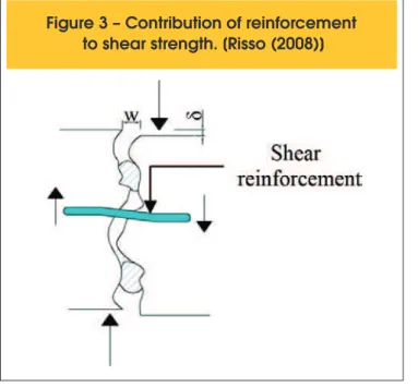
When slip occurs on a surface, the transverse reinforcement at the interface contributes to transfer shear stresses by dowel action. Ac-cording to Araújo (2002), the shear resistance by dowel action due to the transverse reinforcement generally presents lower values than the frictional and mechanical action. The transverse reinforcement increases the frictional resistance between the surfaces in response to a load normal to the interface. If the surface is rough, transverse clearance may occur, which, added to the slip between the surfaces, may cause elongation of the rebar (Figure 3).
The frictional resistance between the contact surfaces increases due to rebar reactions, creating normal compressive stress at the
interface. Araújo (2002) explains that an interface must be clearly deined for concrete members with a high concentration of rebars normal to the plane of the interface and subjected to tangential loads. Otherwise, cracks inclined towards the shear plane are formed (Figure 4).
4. Experimental program
The experimental program consisted of testing 26 direct shear models, in the form of 50 cm high prismatic models, under increas-ing loads. The variables considered in the analysis of these models were: internal thickness of the panel, corresponding to the width of the concrete illing, roughness of the concrete-concrete interface (smooth or rough), and compressive strength of the cast-in-place concrete (CPC). The widths of the region illed with CPC were 7 cm, 9 cm and 13 cm. The compressive strengths of the CPC were
Figure 2 – Application of double panels in shear wall, column, foundations and beams
A
C
B
D
Double panel shear wallFoundations
Column
20 MPa, 29 MPa, and 28.4 MPa. The precast concrete (PCC) panels showed a compressive strength of 27.5 MPa. The surfaces of the interfaces were considered smooth (S) and rough (R).
4.1 Direct shear test of the double panels
The external sides of the panels were on average 3 cm thick. One of the sides of the panel was cast irst (Figure 5a), and the other side was cast three days later (Figure 5b). The precast concrete elements are interconnected by means of electro-welded lattices and stirrups.
The second step consisted of illing the models with CPC between
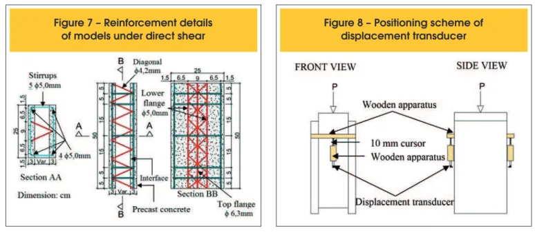
the PCC layers of the panel, resulting in a structural element with concrete of diferent ages. This step was performed in the Struc-tures Laboratory of the Federal University of Uberlandia (Brazil). The surface of the PCC-CPC interfaces of one of the tested series was roughened by waterblasting the aggregates and then clean-ing them (Figure 6). The interfaces of the other series were left untouched after concreting the panel, i.e., without water blasting, and were considered smooth in this study. Figure 7 shows details of the reinforcement and dimensions of the models.
In the direct shear tests, an increasing load was applied upon the central element in the longitudinal direction of the CPC surface in the illed region. Wooden apparatuses were built and ixed onto
Figure 3 – Contribution of reinforcement
to shear strength. [Risso (2008)]
Figure 4 – Cracks inclined toward the shear
plane at the interface. [Araújo (2002)]
faces of the precast concrete panel
A
B
the PCC to measure the displacement at the concrete-concrete interface. Loading was applied in a universal testing machine with 600 kN capacity.
The identiication of each model of the tested series is identi-ied as follows: XS/Y-Exp # for smooth interfaces and XR/Y-Exp # for rough interfaces. The value of X corresponds to the width of the concrete illed region (CPC). The letters S (smooth) or R (rough) correspond to the type of interface. This is followed, after the slash, by the Y value of the compressive strength of the CPC. Lastly, the experimental model is designated Exp #, as indicated in Table 1. The compressive strength of the PCC was about 27.5 MPa in all the tests.
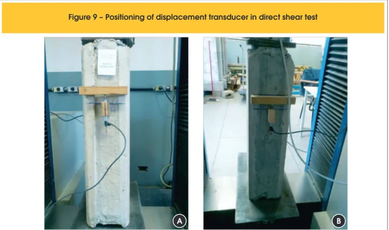
Figure 8 shows a schematic diagram of the positioning of the wooden apparatus and the area where loads were applied, while Figure 9 shows the positioning of the transducers during the test.
5. Numerical modeling
The numerical modeling of the direct shear models was performed us-ing the elements SOLID65, SOLID185, LINK8, TARGE170 and CON-TA174, which are available in the ANSYS software library to simulate the constituent parts of physical models. These elements were applied to simulate the behavior of concrete, steel, and the region of contact be-tween the surfaces of concrete of diferent ages and of the contact with the steel plate on which double lattice panel was supported.
The element SOLID65 was used to simulate the PCC and CPC. This element consists of eight nodes with three degrees of freedom per node: translation in the nodal x, y and z directions, and it can undergo tensile cracking, compressive crushing and plastic deformation. LINK8 was applied to simulate the longitudinal framing and stirrups of the physical models. LINK8 has three degrees of freedom per
Figure 6 – Panel with exposed coarse aggregate
Figure 7 – Reinforcement details
node, i.e., translation in the nodal directions x, y and z. This ele-ment can only simulate tension and compression forces, and can undergo plastic deformation, elongation and large displacements. The inite element TARGE170 was used to represent various “target” surfaces of contact surface elements associated with the element CONTA174. These elements simulate the contact of the surface at the interface of the concrete-to-concrete bond of the models. The pair of contacts represented by the elements TARGE170 and CONTA174 allows friction and cohesion to be
con-sidered, as well as slipping between the bond surfaces. The friction coeicient considered in the numerical analysis was 0.6 for smooth surfaces and 1.0 for rough surfaces.
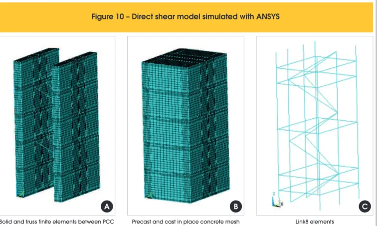
Figure 10 illustrates the discretization of the inite element used in the models subjected to direct shear, showing the indispensable condition of matching nodes with the nodes of the solid elements (CPC and PCC) to generate a stable model, using LINK8 (pinned nodes). With regard to the physical nonlinearity of concrete, the concrete
model was used to represent the behavior of CPC and PCC,
Table 1 – Identification of the direct shear tested models
Series Model Internal width (cm) Type of surface shear fc (MPa)
A 7S/20 - Exp # 7 Smooth 20 B 9S/20 - Exp # 9 Smooth 20 C 13S/20 - Exp # 13 Smooth 20 D 7R/29 - Exp # 7 Rough 29 E 9R/29 - Exp # 9 Rough 29 F 13R/29 - Exp # 13 Rough 29 G 7S/28.4 - Exp # 7 Smooth 28.4 H 9S/28.4 - Exp # 9 Smooth 28.4 I 13S/28.4 - Exp # 13 Smooth 28.4
Figure 9 – Positioning of displacement transducer in direct shear test
A
B
because it allows the material’s failure to be predicted, presenting yielding, cracking and crushing based on Willam-Warnke criterion (Figure 11). The bilinear isotropic hardening model is adopted for steel behaviour (Figure 12). This model applied in LINK8 follows the von Mises yield criterion and lists the yield stress of steel, its modulus of elasticity and its density.
The convergence method for solving the nonlinear system applied here was the full Newton-Raphson method, which, according to
Oliveira (2007), allows the tangent stifness matrix to be updated at each iteration. The adaptive descent feature was activated si-multaneously to the full Newton-Raphson process. This feature should be used when applying elements of surface contact and is only valid when the full Newton-Raphson process is applied. In or-der to improve the convergence for the physical nonlinear analy-sis, the line search feature was enabled.This feature multiplies the incremental displacement vector by a scale factor between 0 and 1.
Figure 10 – Direct shear model simulated with ANSYS
Link8 elements
C
Precast and cast in place concrete mesh
B
Solid and truss finite elements between PCC
A
Figure 11 – Stress x strain concrete behavior
(Unit: kN; cm) [Ansys v.11]
5.1 Results of numerical simulations of the models
subjected to direct shear stress
The next sections describe the numerical results of direct shear strength as a function of the inluence of interface roughness, of width and strength of concrete in the illed region, and of the dowel efect.
5.1.1 Inluence of interface roughness and strength of concrete ill
Figure 13 illustrates the linear and nonlinear physical behavior (NLF) of series C, F and I (13 cm) with respect to the inluence of interface roughness and strength of concrete ill. Series A, D and G (7 cm) and B, E and H (9 cm) showed the same behavior pattern. For the same loading level, models C and I, with smooth interfac-es, show a higher relative displacement than series F with rough interface. It is worth noting that, for the same interface surface, the model with the lowest compressive strength in the illed region (CPC) showed higher displacements.
The numerical rupture force also increases due to roughness of the interface and the concrete compressive strength, varying be-tween 18 and 26% of changing. The roughness interface contribu-tion is less than the concrete compressive strength in the illed region (CPC), about 7%.
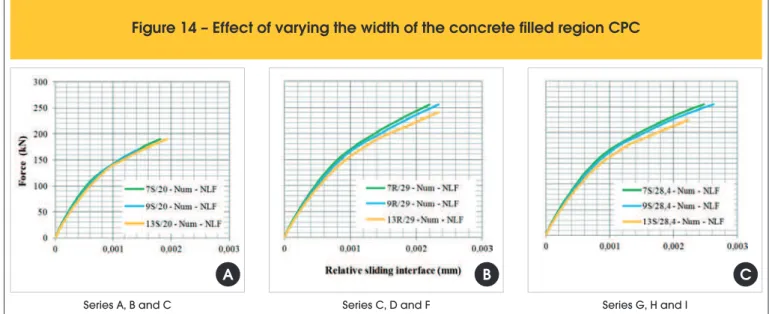
5.1.2 Inluence of the variation in width of the CPC illed region
Figure 14 compares the results of the inluence of the width of the region illed with CPC. For the same amount of relative displace-ment, it was found that the loading level achieved was higher in the models with smaller widths of CPC.
This behavior is explained by the fact that the model with the smaller internal width shows lower stress normal to the interface distributed throughout the section. Conversely, the models that show higher stresses normal to the interface are those with greater widths in the CPC illed region, failing under lower loading. It should be noted that both the higher roughness and higher strength of the concrete ill contribute to the tendency for greater ultimate loading capacity of the model.
Figure 13 – Diagram of force vs. relative slip at the interface in Series C, F and I (13 cm)
F
igure 14 – Effect of varying the width of the concrete filled region CPC
Series A, B and C
A
Series G, H and I
C
Series C, D and F
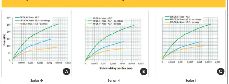
5.1.3 Inluence of the dowel efect
To evaluate the inluence of the reinforcement that crosses the in-terface, or the dowel efect on shear strength, three types of situ-ations were analyzed numerically: without stirrups, without lattice, and with lattice and stirrups (Figure 15).
Models with stirrups and lattice withstand a higher level of loading than the other cases. Thus, it is possible to observe the inluence of the dow-el efect on the shear strength. Moddow-els with lattice and without stirrups withstand on average 71% of the breaking strength of the models with all the reinforcements. Models with stirrups but without lattices reach only 40% of the ultimate strength of the models with stirrups and lat-tices. As the width of the region of CPC (13 cm) increases, the efect of the absence of the stirrups becomes more signiicant (Figure 15c).
5.2 Cracking of the double lattice panels under direct shear
Cracking in the panels subjected to direct shear stress was ana-lyzed in this study for the B Series, since almost all the numerical models showed the same type of cracking. The irst crack occurred at the interface of the model under a load of approximately 25 kN. In general, the same type of cracking and mechanical behavior obtained in the numerical modeling was observed experimentally (Figure 16).
6. Comparison of numerical
and experimental results
The numerical and experimental results of the models revealed
Series G
A
Series I
C
Series H
B
Figure 16 – Rupture of the experimental Series B model
Details of slipping at the concrete interface (PCC and CPC)
Shear deformation of reinforcement
B
C
Cracks at rupture (front and lateral face)
For
ce (kN)
0 50 100 150 200 250 3000 0,005 0,01 0,015 0,02 Relative sliding interface (mm)
13R/29 -Num - NLF 13R/29 -Num - Linear 13R/29 -Exp 2
For
ce (kN)
0 50 100 150 200 250 3000 0,005 0,01 0,015 0,02
Relative sliding interface (mm)
9R/29 - Num - NLF 9R/29 - Num - Linear 9R/29 - Exp 3
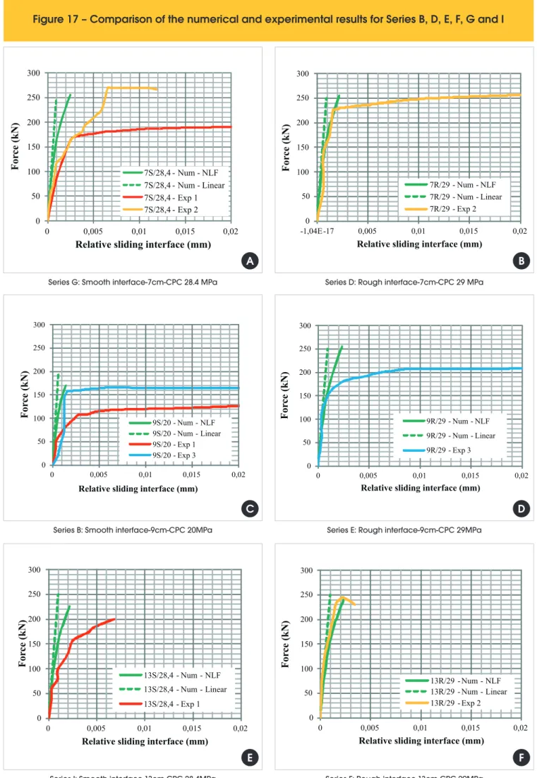
Figure 17 – Comparison of the numerical and experimental results for Series B, D, E, F, G and I
A
C
Series G: Smooth interface-7cm-CPC 28.4 MPaSeries B: Smooth interface-9cm-CPC 20MPa
0 50 100 150 200 250 300
0 0,005 0,01 0,015 0,02
Relative sliding interface (mm)
For
ce (kN)
7S/28,4 - Num - NLF 7S/28,4 - Num - Linear 7S/28,4 - Exp 1 7S/28,4 - Exp 2
B
D
Series D: Rough interface-7cm-CPC 29 MPaSeries E: Rough interface-9cm-CPC 29MPa
For
ce (kN)
0 50 100 150 200 250 300-1,04E-17 0,005 0,01 0,015 0,02 Relative sliding interface (mm)
7R/29 - Num - NLF 7R/29 - Num - Linear 7R/29 - Exp 2
For
ce (kN)
0 50 100 150 200 250 3000 0,005 0,01 0,015 0,02
Relative sliding interface (mm)
9S/20 - Num - NLF 9S/20 - Num - Linear 9S/20 - Exp 1 9S/20 - Exp 3
For
ce (kN)
0 50 100 150 200 250 3000 0,005 0,01 0,015 0,02 Relative sliding interface (mm)
ing of reinforcing bars. The linear and nonlinear responses of the models are presented numerically. The rupture strength achieved experimentally for the series varied widely in the tested models. However, this variation was attributed to the small number of pro-totypes tested for each series. As a matter of fact, a tendency of the increasing of the load-bearing capacity of the models under direct shear stress was observed due the increase in compressive strength of the concrete in the illed region.
Figure 17 illustrates the ratio of force vs. relative slip at the inter-face indicated by the numerical and experimental results of models under direct shear stress of Series B, D, E, F, G and I. Other series showed very similar results.
The models with smooth interfaces showed higher relative slip than the models with rough interfaces, in order of 2 or 3 times greater (Figure 17a,b and Figure 17e,f). In general, the models with rough interfaces presented relative slipping in the order of 2x10⁻³ mm.
The numerical response of the relative sliding interface for the smooth interface tested series showed conservative values com-pared to the experimental tests. The rough interface series showed a good agreement between experimental and numerical response.
7. Conclusions
In general, the results show that the structural set works with-out signiicant slip at the interface. The main conclusions are de-scribed below.
The analyses of the experimental results under direct shear indi-cated that the transfer of stresses at the interface occurred with loss of adhesion. This was caused by detachment between the surfaces, frictional and mechanical forces, and the contribution of the dowel efect, until concrete-to-concrete slippage and rupture occurred, with crushing of the precast concrete in the region of the supports.
The surface roughness of the interface bonding region was an im-portant factor in the increase in direct shear strength. In general, the smooth models with lower compressive strength in the illed region showed slippage 2 or 3 times greater at rupture than the relative slip at the interface of the models with rough surfaces; As for the contribution of the compressive strength of the con-crete in the illed region, an increase was observed in the direct shear strength of concrete with higher compressive strengths. Due to the wide dispersion of results for the experimental models, the average value of this contribution could not be determined. In numerical terms, the models with smooth interfaces showed a 36.61% gain in shear strength in response to the increase in compressive strength of the concrete in the illed region from 20 MPa to 28.4 MPa.
The numerical study indicated that the direct shear strength at the interface was higher in models of smaller width, since they pre-sented lower normal stresses distributed at the interface, thus with -standing higher loading than the other models. Experimentally, due to the small number of tests performed for each variable under analysis, the values of rupture strength varied signiicantly.
Considering the contribution of each portion of reinforcement crossing the interface, the numerical simulations indicated that the higher the geometric ratio of reinforcement the higher the direct shear strength of the structural model. The models with lattices but
els with complete reinforcement. This rate dropped to 40% in the models with only stirrups and without lattices. At break, the stirrup reinforcement of the numerical models under direct shear did not reach the yield point.
8. Acknowledgements
The author gratefully acknowledges the Brazilian research funding agency CAPES (Federal Agency for the Support and Improvement of Higher Education) for a master’s scholarship awarded for this research and the company PREMON the donation of precast con-crete components.
9. References
[1] ANSYS RELEASE. Version 11.0 Documentation. SAS IP, Inc©; 2007.
[2] ASSOCIAÇÃO BRASILEIRA DE NORMAS TÉCNICAS. NBR 6118: Projeto de estruturas de concreto – Procedimento. Rio de Janeiro: ABNT, 2014.
[3] ASSOCIAÇÃO BRASILEIRA DE NORMAS TÉCNICAS. NBR 9062: Projeto e execução de estruturas de concreto pré-mol-dado. Rio de Janeiro: ABNT, 2006.
[4] ARAÚJO, D. L. Cisalhamento na interface entre concreto pré-moldado e concreto pré-moldado no local em elementos submeti-dos à lexão. Thesis (Master Science). Escola de Engenharia de São Carlos, Universidade de São Paulo, 1997.
[5] ARAÚJO, D. L. Cisalhamento Entre Vigas e Lajes Pré-Mol-dadas Ligadas Mediante Nichos Preenchidos com Concreto de Alto Desempenho. Thesis (Doctor Science). Escola de En-genharia de São Carlos, Universidade de São Paulo, 2002. [6] BASS, R. A., CARRASQUILLO, R. L., JIRSA, S. O. Shear
Transfer Across New and Existing Concrete Interfaces, ACI Structural Journal, v. 86, n. 4, p. 383-393, jul./aug. 1989. [7] BENAYOUNE, A., et al. Flexural Behaviour of Pre-cast
Con-crete Sandwich Composite Panel – Experimental and Theo -retical Investigations. Construction and Building Materials, v. 22, p. 580-592, 2008.
[8] EL DEBS, M. K. Concreto Pré-Moldado: Fundamentos e Aplica-ções. Universidade de São Paulo. São Carlos: EDUSP, 2000. [9] HOFBECK, J. A., IBRAHIM, I. O., MATTOCK, A. H. Shear
Transfer in Reinforced Concrete, ACI Journal, Proceedings, v. 66, n. 2, p. 119-128, feb. 1969.
[10] HSU, T. T. C., MAU, S. T., CHEN, B. Theory of Shear Transfer Strength in Reinforced Concrete, ACI Structural Journal, v. 84, n. 2, p. 149-160, mar./apr. 1987.
[11] KABIR, M. Z. Structural Performance of 3-D Sandwich Panels Under Shear and Flexural Loading. Scientia Iranica, v. 12, n. 4 p. 402-408, oct. 2005.
[12] LACERDA, B. M. Estudo Numérico e Experimental do Com-portamento de Painéis Duplos Treliçados Preenchidos com Concreto Moldado no Local. Thesis (Master Science). Univer-sidade Federal de Uberlândia, 2013.
[14] OLIVEIRA, D. M. Estudo dos Processos Aproximados Uti-lizados para a Consideração das Não-linearidades Física e Geométrica na Análise Global das Estruturas de Concreto Armado. Thesis (Doctoral Science). Universidade Federal de Minas Gerais, 2007.