2
Mitsubish Electric Research Labs, USA [email protected]
3
Epson Palo Alto Research Labs, USA [email protected]
Abstract
We present a novel method to reduce the effect of spec-ularities in digital images. Our approach relies on a sim-ple modification of the capture setup: a multi-flash cam-era is used to take multiple pictures of the scene, each one with a differently positioned light source. We then formu-late the problem of specular highlights reduction as solv-ing a Poisson equation on a gradient field obtained from the input images. The obtained specular reduced image is further refined in a matting process with the maximum composite of the input images. Experimental results are demonstrated on real and synthetic images. The entire setup can be conceivably packaged into a self-contained device, no larger than existing digital cameras.
Keywords: Specularities, Multi-Flash Imaging, Pois-son Equation.
1. Introduction
The reflection of light from surfaces in real scenes is generally classified into two main categories: diffuse and specular. The diffuse component results from light rays
∗Correspondence Author: Rogerio Feris - 6661 Berkshire Terrace apt.
18 - Goleta, CA 93117 - USA - (805)284-5392 - [email protected]
penetrating the surface, undergoing multiple reflections, and re-emerging [2]. In contrast, the specular component is a surface phenomenon - light rays incident on the sur-face are reflected such that the angle of reflection equals the angle of incidence. Light energy due to specular re-flections is often concentrated in a compact lobe, causing strong highlights (bright regions) to appear in the image.
These bright spots, also known as specularities, play a major role in many computer graphics and vision prob-lems. They provide a true sense of realism in the envi-ronment, reveal important local curvature information [3] and may even provide additional cues for object recogni-tion [4]. However, in most cases, specular highlights are undesirable in images. They are often considered as an-noyance in traditional photography and cause vision algo-rithms for segmentation and shading analysis to produce erroneous results. If the sensor direction is varied, high-lights shift, diminish rapidly, or suddenly appear in other parts of the scene. This poses a serious problem for vi-sion methods that rely on image correspondences, such as stereo or motion algorithms.
Figure 1. Multi-flash camera setups used in [1] for depth edge detection. From left to right: 4-flash setup, 8-flash setup
and dynamic scenes setup. Our goal in this paper is to exploit multi-flash imaging for specular reflection reduction.
that highlights appear in regions with no variation of ma-terial type or surface normal. In fact, reliably removing specularities in textured regions remains a challenging problem.
In this paper, we address the problem of reducing the effect of specularities in digital images by taking a dif-ferent approach1 . Rather than relying in one single age as most previous methods, we capture a set of im-ages of the scene with different lighting conditions. Our work belongs to an emerging class of computer graph-ics techniques that process multiple images acquired with the same viewpoint but under different conditions, such as different illumination, focus or exposure [8, 9, 1].
Our capture setup is a multi-flash camera, a self-con-tained device that we have recently proposed for depth edge extraction and non-photorealistic rendering [1]. By observing that specularities shift according to the differ-ent positions of the flashes, we are able to significantly reduce or completely remove specular highlights in the scene. More specifically, we formulate this problem as solving a Poisson equation on a gradient field obtained from the input images. This allows us to remove spec-ularities in objects with different curvatures and textured regions.
We will detail our approach in Section 2 and present our experimental results in Section 3. In Section 4, we discuss advantages and limitations of our method. In Sec-tion 5, we describe implementaSec-tion details and conclude the paper in Section 6, with final remarks and future work.
1Based on “Specular Reflection Reduction with Multi-Flash Imaging”,
by Feris, Raskar, Tan, and Turk, which appeared in Proceedings of SIB-GRAPI/SIACG 2004 (ISBN 0-77=695-2227-0). c2004 IEEE.
2. Specular Highlights Reduction
In this section we introduce our proposed method for specular highlights reduction. We start describing our capture setup and then present our gradient domain al-gorithm.
2.1. Multi-Flash Imaging
Instead of taking one single picture of the scene, we use a multi-flash camera withnflashes to acquiren
im-ages from the same viewpoint, each one with a differently positioned flash. We have already successfully used this setup for detection of depth edges, with applications in stylized rendering [1], fingerspelling recognition [10] and medical imaging [11]. Figure 1 shows our different multi-flash setups for static and dynamic scenes. Note that the position of each flash in these prototypes was chosen to better detect depth edges. We refer to [1] for details about our depth edge detection method based on shadows. Now we will show how multi-flash cameras can be used for reliable removal and reduction of specularities.
2.2. Approach
Our method is based on the observation that specular spots shift according to the shifting of light sources that created them. We need to consider three cases of how specular spots in different light positions appear in each image:
(i) shiny spots remain distinct on a specular surface. (ii) some spots overlap.
(iii) spots overlap completely (no shift).
We show that for cases (i) and (ii), which often oc-cur in practice, our method successfully removes specular highlights.
not static.
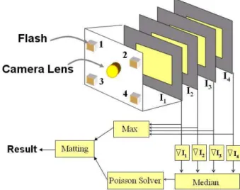
LetIk,1≤k≤nbe an input image taken with light
sourcekandImax(x) =maxk(Ik(x))be the maximum
composite of the input images. We compute the specular-reduced image through the following steps:
1. Compute intensity gradient,Gk(x, y) =∇Ik(x, y)
2. Find median of gradients, G(x, y) = mediank
(Gk(x, y))
3. Reconstruct imageIˆwhich minimizes
∇Iˆ−G
4. UseImaxto improve result in a matting process. This algorithm is illustrated in Figure 2, considering a camera with four flashes. We will detail the method used for reconstructing imageIˆ(step 3) in Section 2.3. The alpha matting process (step 4) will be described in Section 2.4.
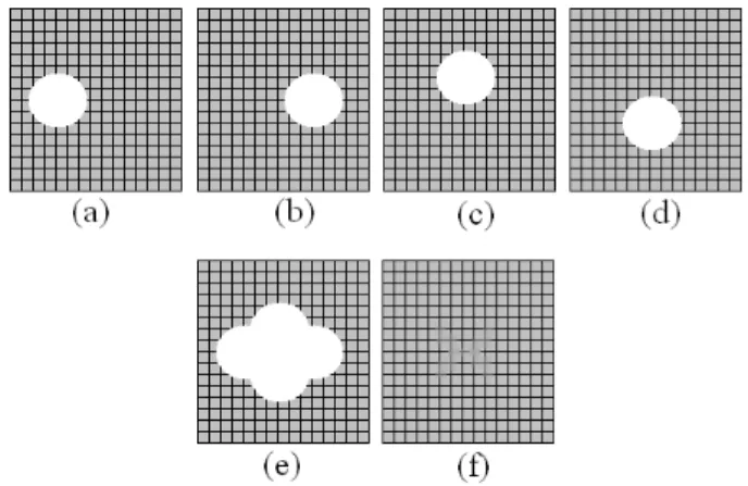
Figure 3 shows a simple example to illustrate our me-thod in all three cases mentioned above. For each case, we created four images with manually drawn specular-ities. The first column in the figure corresponds to the max composite of the four images (Imax), the second cor-responds to the median of intensities (Imedian) and the third column is the output of our method - the reconstruc-tion from the median of gradients (Iintrinsic).
Note that if we consider Imedian, specularities are not eliminated in case (ii), where spots overlap. On the other hand, our method is able to handle cases (i) and (ii), which often occur in practice. If specularities do not move among images, our method fails to remove them.
It is worth mentioning that specularities could also be removed by just taking the min composite of the images, but in this case we would have the presence of shadows, which are not desirable. Since the boundaries of shadows rarely overlap, they are also eliminated in our method.
2.3. Image Reconstruction from Gradient Fields
Image reconstruction from gradients fields, an approx-imate invertibility problem, is still a very active research area. InR2, a modified gradient vector fieldGmay not be
integrable. In other words, there might not exist an image ˆ
I such that G = ∇Iˆ. In fact, the gradient of a poten-tial function must be a conservative field i.e., the gradient
Figure 2. The basic idea of our algorithm for specular
reflection reduction.
∇Iˆ= (∂Iˆ
∂x, ∂Iˆ
∂y)must satisfy:
∂2Iˆ
∂x∂y = ∂2Iˆ
∂y∂x (1)
This condition is rarely verified for the gradient fieldG. As noted by Frankot and Chellappa [13], one possi-ble solution to this propossi-blem is to orthogonally projectG
onto a finite set of Fourier basis functions spanning the set of integrable vector fields. In our method, we employ a more direct and efficient approach, in a similar way to the work of Fattal et al. [14]. We search the space of all 2D potential functions for a functionIˆwhose gradient is the closest toGin the least-squares sense. In other words,
ˆ
Ishould minimize the integral:
F(∇I, Gˆ )dxdy, (2)
whereF(∇I, Gˆ ) =∇Iˆ−G2= (∂Iˆ
∂x−Gx)2+ ( ∂Iˆ ∂y − Gy)2.
According to the Variational Principle, a function Iˆ
that minimizes the integral in (2) must satisfy the Euler-Lagrange equation:
∂F ∂Iˆ −
d dx
∂F ∂Iˆx
− d
dy ∂F ∂Iˆy
= 0, (3)
which is a partial differential equation inIˆ. Substituting
Fwe obtain the following equation:
2(∂2Iˆ
∂x2 −
∂Gx ∂x ) + 2(
∂2Iˆ
∂y2 −
∂Gy
Figure 3. Illustration of the three cases. Note that if we
consider only the median of image intensities (instead of median of gradients), we have problems in case (ii). Our method based on the intrinsic image handles cases (i) and (ii) which often occur in practice. If specularities do not move among images our method fails to remove them.
Dividing by 2 and rearranging terms, we obtain the well-known Poisson Equation:
∇2Iˆ=divG (5)
where ∇2 is the Laplacian operator defined as ∇2Iˆ = ∂2Iˆ
∂x2+ ∂2Iˆ
∂y2, anddivGis the divergence of the vector field G, defined asdivG=∂Gx
∂x + ∂Gy
∂y .
We have used the standard full multigrid method [15] to solve the Poisson equation. We pad the images to square images of size the nearest power of two, before applying the integration, and then crop back the result to the original size.
2.4. Alpha Matting
As we will show in our experiments, our technique is effective to reduce the effect of specularities in digital images, but may also introduce some low-contrast effects, which might be undesirable for some applications (e.g., photography).
We improve the quality of our result in a matting pro-cess with the maximum composite image Imax. We place the flashes strategically so that every point in the scene that is shadowed in some image is also captured without being shadowed in at least one other image. Thus,
Imaxis a shadow-free image, with the problem of being affected by specularities.
Our observation is that we can detect specularities in
Figure 4. (a-d) Four images with manually drawn
specu-larities along a textured region. (e) Max composite image. (f) Result of our method.
Imax by taking the difference between Imax and the reconstructed specular-reduced imageIˆ. This difference is then used as an alpha channel for matting, so that we replace the specular regions inImax by the correspon-dent specular-reduced regions inIˆ. More specifically, we computed our final resultRas follows:
α = Imax−Iˆ N
R = αIˆ+ (1−α)Imax (6)
where N is a normalizing constant factor, calculated so that values ofαrange from zero to one .
An alternative to the matting process would be to thresholdαand use image inpainting techniques [16, 17] to fill in the specular regions inImax(determined byα).
3. Results
This section presents our experimental results, which were carried out with synthetic and real images, consid-ering objects with different local curvature and textured regions.
3.1. Synthetic Images
We first demonstrate our method in synthetic images, showing that it can reliably remove specularities in tex-tured regions, as long as spots shift among images.
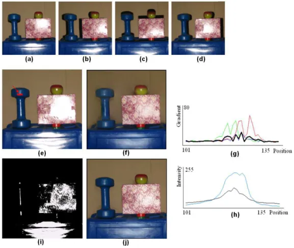
Figure 5. (a-d) Four images taken with our multi-flash camera. (e) Max composite image. (f) Specular-reduced image
using our method. (g) Magnitudes of gradients along the scanline showed in (e). Dashed lines correspond to gradients of different images and the solid line is the median of gradient magnitudes. (h) Intensity of max composite along the scanline (dashed line) and intensity of reconstructed specular-reduced image (solid line). (i) Alpha channel used for matting. (j) Our final result.
are able to eliminate the specularities, while preserving the texture.
3.2. Real Images
We now show the usefulness of our method in real scenes. Figure 5a-d shows four images taken with our multi-flash setup depicted in Figure 1a. Note that the im-ages contain shadows and specularities. The max com-posite image, shown in Figure 5e, has no shadows, but contains all specular highlights. Our specular-reduced gradient reconstruction is shown in Figure 5f. We have chosen objects in the scene with different local curvature and included also a textured box. We are able to sig-nificantly remove specular highlights despite these con-ditions.
Figure 5g shows the magnitudes of gradients along the scanline showed in the max composite image. Dashed lines correspond to gradients of different images and the solid line is the median of gradient magnitudes. Figure 5h shows the intensity of the max composite image along the scanline (dashed line) and the intensity of the recon-structed specular-reduced image (solid line).
The quality of our result is improved through the al-pha matting step. Figure 5i shows the computed alal-pha channel, which allows us to detect specularities. Our final result after matting is shown in Figure 5j.
Figure 6. (a). Image taken with one of the flashes. (b). Maximum composite image. (c). Detection of specularities
(alpha channel). (d) Our final result after matting.
Figure 7. (a) Image taken with one of the flashes. (b) Gradient reconstructed image. (c) Result after matting.
for this example (Figure 6d), shadows are eliminated and specularities are significantly reduced.
Another demonstration of our technique is given in Figure 7, where we show an input image taken with one of the flashes (Figure 7a), the gradient reconstructed image (Figure 7b), and our final result after matting(Figure 7c). We note in this case that the gradient reconstructed im-age has some blur and shadow effects (due to overlapped shadow boundaries). The quality of our result is improved after alpha matting.
The computational time required to obtain the specular-free images is about one second on a 3GHz Pen-tium 4, considering images with resolution 640x480.
4. Discussion
As we already mentioned, our method fails when specular highlights do not shift among images captured with different flashes. Fortunately, this case is not
prob-lematic for many computer vision methods that rely on image correspondences. Other sources of failure include scenes with e.g., rough surfaces or silk cloths.
In our method, regions covered by specular highlights in one image may be specular-free in others, since bright spots often shift due to our multi-flash scheme. This al-lows us to “uncover” these regions, posing an advantage over previous approaches that rely on a single image.
By solving the Poisson partial differential equation, we eliminate most highlights and also shadows in the im-age. This compares favorably with the max composite (which has no shadows but is full of specularities), the min composite (which is specular-reduced but also full of shadows) and the median of intensities (which has prob-lems when spots overlap, as shown in Figure 3). In ad-dition, our method is not affected by objects as bright as specularities in the scene (see Figure 6, which is clearly a problem for thresholding-based techniques.
more accurate results could be obtained by using more light sources with strategic positions. Using only two flashes would not be a good choice, due to the fact that the gradient of the boundary of a specularity in one image would be only attenuated (not removed) when taking the mean with the other image. Choosing the minimum gra-dient could help in this case, but it would create a problem for textured regions.
In addition to reduce the effect of specular highlights in digital images, our method also detects specularities, which may be useful in other applications, such as ob-ject shape information acquisition [2] and interactive cre-ation of technical illustrcre-ations, where the user may decide whether to keep or remove specularities. Our detected specular regions could also be used as input for image in-painting methods, which often require manual labeling of such regions [17].
Our technique could be applied for specular reflection reduction in traditional photography and also for improv-ing computer vision methods. We show in Figure 8 that using our specular-reduced image significantly improves depth edge detection [1]. Figure 9 shows more results in challenging specular scenes.
Finally, we need to mention that we are processing “active specularities”, created by our light sources, rather than highlights due to ambient light. The use of flashes might be useful in many situations, such as in dark scenes, or even for vision methods based on active lighting.
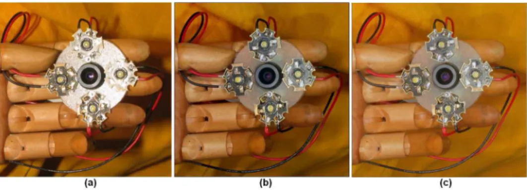
5. Implementation
Our basic prototype for static scenes makes use of a four MegaPixel Canon Powershot G3 digital camera. The four booster (slaved Quantarray MS-1) 4ms duration flashes are triggered by optically coupled LEDs turned on sequentially by a PIC microcontroller, which in turn is interrupted by the hot-shoe of the camera.
Figure 9. Depth edge detection results in challenging specular scenes.
6. Conclusions
We have presented a new method for specular reflec-tion reducreflec-tion in digital images. Rather than relying on a single image, we capture multiple images of the scene under different lighting conditions. Based on the informa-tion that highlights often shift according to the posiinforma-tion of the light sources, we formulate the problem of specularity removal as solving a Poisson equation on a gradient field obtained from the input images.
We basically improved and presented another func-tionality for the multi-flash camera, recently proposed for depth edge detection and stylized rendering [1]. As future work, we plan to exploit other imaging parameters, such as variable wavelength (coloured flashes) to improve our techniques.
References
[1] R. Raskar, K. Tan, R. Feris, J. Yu, and M. Turk, “A non-photorealistic camera: depth edge detection and stylized rendering using multi-flash imaging,”
SIG-GRAPH’04 / ACM Transactions on Graphics (to ap-pear), 2004.
spec-ularities using color and polarization,” in
Interna-tional Conference on Computer Vision and Pattern Recognition, New York City, USA, 1993, pp. 583–
590.
[3] M. Oren and S. Nayar, “A theory of specular sur-face geometry,” International Journal of Computer
Vision, vol. 2, pp. 105–124, 1997.
[4] M. Osadchy, D. Jacobs, and R. Ramamoorthi, “Us-ing specularities for recognition,” in International
Conference on Computer Vision, Nice, France,
2003.
[5] G. Klinker, S. Shafer, and T. Kanade, “The measure-ment of highlights in color images,” International
Journal of Computer Vision, vol. 2, pp. 7–32, 1988.
[6] L. Wolff and T. Boult, “Constraining object fea-tures using a polarization reflectance model,” IEEE
Transactions on Pattern Analysis and Machine In-telligence, vol. 16, no. 6, pp. 635–657, 1991.
[7] S. Lee, Understanding of Surface Reflections in Computer Vision by Color and Multiple Views,
Ph.D. thesis, University of Pennsylvania, 1991.
[8] M. Cohen, A. Colburn, and S. Drucker, “Image stacks,” Tech. Rep. MSR-TR-2003-40, Microsoft Research, 2003.
[9] D. Akers, F. Losasso, J. Klingner, M. Agrawala, J. Rick, and P. Hanrahan, “Conveying Shape and Features with Image-Based Relighting,” in IEEE
Vi-sualization, 2003.
[10] R. Feris, M. Turk, R. Raskar, K. Tan, and G. Ohashi, “Exploiting Depth Discontinuities for Vision-based Fingerspelling Recognition,” in IEEE Workshop on
Real-time Vision for Human-Computer Interaction (in conjunction with CVPR’04), Washington DC,
USA, 2004.
[11] K. Tan, J. Kobler, P. Dietz, R. Feris, and R. Raskar, “Shape-Enhanced Surgical Visualizations and Med-ical Illustrations with Multi-Flash Imaging,” in
Con-ference on Medical Image Computing and Com-puter Assisted Intervention, France, 2004.
[12] Y. Weiss, “Deriving intrinsic images from image sequences,” in Proceedings of International
Confer-ence on Computer Vision, 2001, pp. 68–75.
[13] R. Frankot and R. Chellappa, “A method for en-forcing integrability in shape from shading algo-rithms,” IEEE Transactions on Pattern Analysis and
Machine Intelligence, vol. 10, no. 4, pp. 439–451,
1988.
[14] R. Fattal, D. Lischinski, and M. Werman, “Gradi-ent Domain High Dynamic Range Compression,” in Proceedings of SIGGRAPH 2002. ACM SIG-GRAPH, 2002, pp. 249–256.
[15] W. Press, S. Teukolsky, W. Vetterling, and B. Flan-nery, Numerical Recipes in C: The Art of Scientific
Computing , Pearson Education, 1992.
[16] M. Bertalmio, G. Sapiro, V. Caselles, and C. Ballester, “Image inpainting,” in Siggraph 2000,
Computer Graphics Proceedings. 2000, pp. 417–
424, ACM Press / ACM SIGGRAPH / Addison Wesley Longman.
[17] P. Tan, S. Lin, L. Quan, and H. Shum, “High-light removal by illumination-constrained inpaint-ing.,” in International Conference on Computer
![Figure 1. Multi-flash camera setups used in [1] for depth edge detection. From left to right: 4-flash setup, 8-flash setup and dynamic scenes setup](https://thumb-eu.123doks.com/thumbv2/123dok_br/18976662.455549/2.892.222.717.123.290/figure-multi-flash-camera-setups-detection-dynamic-scenes.webp)