367
Radiol Bras. 2011 Nov/Dez;44(6):367–373
Simulation and dosimetric analysis of proton and carbon ion
therapy in the treatment of uveal melanoma
*
Simulação e análise dosimétrica de protonterapia e íons de carbono no tratamento do melanoma uveal
Marília Tavares Christóvão1, Tarcisio Passos Ribeiro de Campos2, Bruno Machado Trindade3
Objective: The present paper addresses the dosimetric evaluation of carbon ion radiotherapy as compared with proton therapy. Materials and Methods: Computer simulations were undertaken with the Geant4 (GEometry ANd Tracking) code. An eye model discretized into voxels and implemented in the Siscodes system (computer system for dosimetry in radiation therapy) was utilized to generate and superimpose depth dose profiles and isodose curves. Different values for beam energy were adopted in the simulations of carbon ion beams, while in the simulation with proton beams irradiation line devices were included with different absorbing material thicknesses. Results: The simulations outputs were processed and integrated into the Siscodes to generate the spatial dose distribution in the eye model, considering changes in the beam entrance position. The dose rates were normalized as a function of the maximum dose for a beam at a specific entrance position, incident particle energy and number of incident carbon ions and protons. Conclusion: The described benefits together with the presented results contribute to the development of clinical applications and researches on carbon ion and proton therapy.
Keywords: Carbon ion therapy; Proton therapy; Geant4; Siscodes.
Objetivo: Este artigo apresenta a avaliação dosimétrica da radioterapia por íons de carbono em comparação à proton-terapia. Materiais e Métodos: As simulações computacionais foram elaboradas no código Geant4 (GEometry ANd Tracking). Um modelo de olho discretizado em voxels implementado no sistema Siscodes (sistema computacional para dosimetria em radioterapia) foi empregado, em que perfis de dose em profundidade e curvas de isodose foram gera-dos e superpostos. Nas simulações com feixe de íons de carbono, distintos valores de energia do feixe foram adota-dos, enquanto nas simulações com feixe de prótons os dispositivos da linha de irradiação foram incluídos e diferentes espessuras do material absorvedor foram aplicadas. Resultados: As saídas das simulações foram processadas e in-tegradas ao Siscodes para gerar as distribuições espaciais de dose no modelo ocular, considerando alterações do posicionamento de entrada do feixe. Os percentuais de dose foram normalizados em função da dose máxima para um feixe em posição de entrada específica, energia da partícula incidente e número de íons de carbono e de prótons in-cidentes. Conclusão: Os benefícios descritos e os resultados apresentados contribuem para o desenvolvimento das aplicações clínicas e das pesquisas em radioterapia ocular por íons de carbono e prótons.
Unitermos: Radioterapia por íons de carbono; Protonterapia; Geant4; Siscodes. Abstract
Resumo
* Study developed at Department of Nuclear Engineering, Universidade Federal de Minas Gerais (UFMG), Belo Horizonte, MG, Brazil.
1. PhD, Technologist at Centro de Desenvolvimento da Tec-nologia Nuclear (CDTN), Belo Horizonte, MG, Brazil.
2. PhD, Professor, Department of Nuclear Engineering, Uni-versidade Federal de Minas Gerais (UFMG), Belo Horizonte, MG, Brazil.
3. Post-Doctorate, Department of Nuclear Engineering, Uni-versidade Federal de Minas Gerais (UFMG), Belo Horizonte, MG, Brazil.
Mailing Address: Marília Tavares Christóvão. Avenida Presidente Antônio Carlos, 6627, Campus da UFMG, Pampulha, Caixa Postal 941. Belo Horizonte, MG, Brazil, 31270-901. E-mail: marilia@ cdtn.br
Received November 16, 2010. Accepted after revision Octo-ber 25, 2011.
Christóvão MT, Campos TPR, Trindade BM. Simulation and dosimetric analysis of proton and carbon ion therapy in the treatment of uveal melanoma. Radiol Bras. 2011 Nov/Dez;44(6):367–373.
As a consequence, healthy tissues located anteriorly and posteriorly to the Bragg peak can be preserved, while increasing the dose delivered to the target tissue, thus obtain-ing a higher rate of tumor control through the variation of physical parameters ap-plied in the therapy.
In carbon ion therapy, the beams are generally applied in a narrow format called pencil beam. The absorbed energy is depos-ited over the whole target through multiple pencil beams of particles with incident energy covering a wide spectrum, with lower lateral and scattered radiation as compared with proton beams. However, carbon ions present ionization after the Bragg peak, exposing regions immediately cidence—, has undergone significant
changes over time, with increasing intro-duction of modalities that allow preserva-tion of the eyeball, as local resecpreserva-tion, brachytherapy and external radiotherapy.
The utilization of proton and carbon ion in external radiotherapy is advantageous as it provides a spatial form of ionizing energy deposition that is predominant at the end of the pathway of incident particles, repre-sented by a curve whose maximum ampli-tude is known as Bragg peak(1).
The depth of occurrence of Bragg peak depends on the initial energy of incident particle; thus, the site of maximum depo-sition of ionizing energy is controlled by the initial velocity of the incident particle.
INTRODUCTION
in-posterior to the peak to doses correspond-ing to 10% to 20% of the value at the Bragg peak(1).
Carbon ion therapy is indicated in cases of T2 and T3 lesions(2) located at a distance
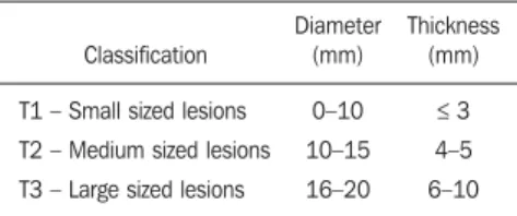
≤ 3 mm from the optic disk and for proton and photon-resistant tumors(3), as described on Table 1.
posited dose(7). The three-dimensional model ocular region was utilized to gener-ate depth dose profiles and isodose curves. In the voxelmodel of the ocular region, the main structures such as the ocular bulb, muscles and optic nerve were represented. Such non-isotropic model comprised 82 × 100 × 43 voxels, corresponding to a vol-ume of 41 × 50 × 38.7 mm3, representing a matrix whose volume element measured 0.5 × 0.5 × 0.9 mm3(8). Water was the ma-terial adopted for each voxel where the carbon ions and protons transport occurred; but the isodoses were plotted superimposed over the material present in the eye phan-tom.
Considering the detailing of the proton therapy study based on such computational environment, dosimetric evaluations dedi-cated to proton therapy were published(9). In the present study, for the purpose of comparisons between different therapeutic modalities, the simulations utilizing carbon ion and proton beams were performed with the same tools, model and computational environment.
Simulation parameters
The beam particle release system uti-lized in the simulations was the passive type, according to the parameters defined in the Geant4 hadrontherapy application. The passive system relies on devices along the irradiation line to produce a homoge-neous dose field and to degrade and modu-late the beam energy(10). Thus, for simula-tions with protons beam the passive system was utilized, where the beam entrance po-sition is at the beginning irradiation line, comprising all line elements, the modula-tion system was not activated. The beams range and applied dose are defined by physical parameters of the utilized compo-nents, such as absorbing material and col-limators, with the proton kinetic energy being defined at 62 MeV. The parameters regarding the thickness of absorbing mate-rial constituted of polymethylmethacrylate (PMMA), applied in the degradation of the proton beams were 6.0 and 8.0 mm. The beam can move along the X and Y coordi-nates, changing the position of the Bragg peak within the eyeball, simulating the ir-radiation in different regions of the target. In clinical applications, the target volume
dimensions should be taken into consider-ation in the collimator configurconsider-ation.
For the simulations with carbon ion beams, the ion source position is at 30 cm from the target, utilizing only the final col-limator, with a diameter of 5.0 mm, as a part of the passive system. The beam range is defined by the employed energy and the beam was moved, changing the site of the dose deposition to simulate the irradiation in different regions of the target. For ions, the specific energy of the incident particles is defined as the ratio between total energy and the atomic mass number (MeV.amu–1 or MeV.u–1)(11).
The number of incident particles uti-lized for the simulations with proton beam is 100 times greater than that the number for the carbon ion beam, following the values presented in the hadrontherapy fa-cility(12,13). A synchrotron accelerates pro-tons up to 250 MeV and carbon ions up to 430 MeV/u, with extraction of up to 1011 protons per second and 109 ions per
sec-ond(12,13). In order to calculate the applied
carbon ion current, one must consider the carbon ions charge. On its turn, the total kinetic energy of the ions was obtained by multiplying the energy/mass unit by the carbon-12 mass.
In heavy ion radiotherapy planning, a pencil beam is defined and its displacement is defined according to the target position and dimensions, considering the preserva-tion of sensitive structures such as the op-tic nerve, the lacrimal gland and the crys-talline. The simulations for proton and car-bon ion beams dosimetry followed a pen-cil beam protocol without modulation.
Depth absorbed dose and dose rate spatial profiles
In radiation therapy, the evaluation of dose distribution in target volume is essen-tial in order to assure that the dose deposi-tion is limited to the target, preserving ad-jacent healthy tissues. The eye model implemented in the Siscodes was utilized to generate the depth dose profiles and the isodose curves(7).
The results from the simulations with the Geant4 were translated in Siscodes as depth dose distribution surfaces, superim-posed to the ocular voxel model. The simu-lation output files record data on the energy Table 1 Uveal melanoma staging(2).
Classification
T1 – Small sized lesions
T2 – Medium sized lesions
T3 – Large sized lesions
Diameter (mm)
0–10
10–15
16–20
Thickness (mm)
≤ 3
4–5
6–10
A high radiation dose accurately applied in association with the high linear energy transfer (LET) of the carbon ion beam en-hances the tumor control, an essential fac-tor to achieve satisfacfac-tory treatment out-comes(4,5).
The objective of the present article is the dosimetric evaluation of radiotherapy with carbon ion and proton pencil beams in ocu-lar tumors. Results from computer simula-tions based on the Geant4 (GEometry ANd Tracking) code utilized for simulation of particle transport in matter, will be pre-sented.
MATERIALS AND METHODS
Computational environment and software tools
de-deposited on the X, Y, and Z voxel coordi-nates in the AIDA format for generation of distribution graphs and histograms, and in ASCII format.
The output file of the simulation in ASCII at the Geant4 is treated by means of a specific in house developed code which converts the code’s output file into the Siscodes format, in MCNP, and calculates the deposited dose rate on each voxel by means of the ratio between the deposited energy in MeV and the specific mass of each voxel, converted into Gy/p units. Such value is adjusted by the RBE factor, result-ing in GyE/p (grays equivalent per incident particle).
The dose unit recommended for carbon ion and proton radiotherapy is GyE, calcu-lated by multiplying the physical dose ex-pressed in Gy by the RBE, considering the value 3 for carbon ion radiotherapy and 1.1 for proton therapy, following recommenda-tions included in clinical trials(1,3,4,14).
Also, the total absorbed dose rate is mul-tiplied by the RBE for carbon ion or pro-ton, whose result is unit of incident par-ticle(4,15).
The dose released by the carbon ion beam is deposited on a geometry in voxel of material and format defined, which is then converted into the Siscodes.
The clinical dose adopted for carbon ion is the dose applied in cases of uveal mela-noma, 70 GyE, in five sessions(3,4). For the treatment of uveal melanoma with protons, the total dose applied is about 60 GyE re-leased in four fractions of 15 GyE(14).
RESULTS
Simulations with carbon ion beam
In the simulations performed without modulation, with processing of 1.0 × 10⁴ carbon ions, the range and applied current were highlighted.
The carbon ion beam energies ranged from 62 to 90 MeV/u. The ranges in the target volume were 11.0 to 21.5 mm, re-spectively. For each particle kinetic energy applied, simulations were performed with beam displacements, radially in 5.0 mm at right and 7.0 mm at left from the center of the eye lens in the voxel model.
The main results obtained in the simu-lations with carbon ion beam (see Table 2)
were the maximum dose (MD) produced per unit of incident particle and the num-ber of incident carbon ions and applied current (nA) required to achieve the dose of 14 GyE, corresponding to one session in the treatment of ocular melanomas. It is possible to observe that the beam current required to achieve 14 GyE presents non-linear variation with the total energy of the incident proton, in the range of 1.14 to 1.53 nA. The lowest current, 1.14 nA × 10–4, occurs for 840 MeV of carbon-12.
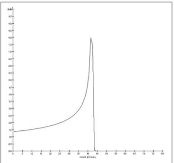
The Bragg peak for carbon-12 beams was well defined. As an example, a typical Bragg peak was reproduced on Figure 1. It was generated without beam modulation,
by the pencil beam with a final collimator diameter of 5 mm and displacement of 7.0 mm at left of the center of the eye lens in the voxel model, with incidences of 1.0 × 10⁴ carbon ions and energy of 1,080 MeV or 90 MeV/u. In such a case, the maximum deposited dose was 3.74 GyE/p, in a pro-cessing time corresponding to 8 hours and 59 minutes. The range of the Bragg peak was 21.5 mm, as presented on the X axis expressed in voxels with a volume of 0.5 mm3.
Similarly to the Bragg peaks, the spa-tial dose distributions in the simulation on the ocular model are well defined, with low lateral scattering. Figures 2 and 3 present
Table 2 Data regarding simulations with carbon ion beams.
Eo in MeV (MeV/u)
744 (62)
840 (70)
960 (80)
1,080 (90) Dfl (mm)
5.0 7.0
5.0 7.0
5.0 7.0
5.0 7.0
Pt
4:17′ 5:25′
5:13′ 6:04′
6:58′ 7:45′
8:20′ 8:59′
Range (mm)
11.0
14.0
17.5
21.5
MD (GyE/p) × 10–5
3.68 3.70
4.74 4.94
4.03 3.95
3.65 3.74
Incident ions (per session 14 GyE)
× 105
1.59 1.58
1.23 1.18
1.45 1.48
1.60 1.56
I (nA) × 10–4
1.53 1.52
1.19 1.14
1.40 1.43
1.54 1.50
Eo, energy of the carbon ion beam expressed in MeV and MeV/u; Dfl, beam entrance position in relation to the
normal and central axes of the eye lens in the voxel model, 5.0 mm at right and 7.0 mm at left; Pt, processing time; MD, maximum dose produced by carbon ions per unit of incident particle; I, current of the particle beam.
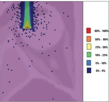
such spatial dose distributions generated at Siscodes, with incidences of 1.0 × 10⁴ car-bon ions, and energies of 840 MeV (70 MeV/u) and 960 MeV (80 MeV/u), respec-tively.
In the cases presented on Figures 2 and 3, the maximum deposited doses were 4.94 and 4.03 GyE/p. The dose rates were nor-malized as a function of the maximum dose for beam entrance in position, incident par-ticle energy and incident carbon ions num-ber. The processing times were 6 hours and 4 minutes and 6 hours and 58 minutes, re-spectively.
Simulations with proton beam
The simulations performed without modulation, processing 1.0 × 10⁶ protons, were comparatively performed with the carbon simulations. For such simulations, all devices in the irradiation line were in-cluded(10,14), with the distance covered by the proton beam up to the target corre-sponding to 2.70 m. The collimator diam-eter of 5.0 mm and energy of 62 MeV were maintained for all the simulations. The beam range achieved 23.0 and 20.5 mm respectively for application of 6.0 and 8.0 mm of absorbing material.
The main results obtained are presented on Table 3 as follows: maximum dose (MD) produced/unit of incident particle, number of incident protons and applied current (nA) required to achieve the dose of 15 GyE, corresponding to one session in the treatment of ocular melanoma by pro-ton therapy. A current of 3.91 to 5.54 nA can be observed in this case. The number of incident protons required to achieve the dose of 15 GyE at the maximum range positions was 3.05 to 4.12 × 10¹⁰.
The spatial dose distributions on the eye model were also reproduced. The simula-tions were performed with proton beam with energy of 62 MeV, with an incidence of 1.00 × 10⁶ protons. In the reproduced cases, displacement of the proton beam entrance position was observed. Poly-methylmethacrylate was the absorbing material utilized. The maximum deposited doses were 4.14 and 5.59 GyE/p at the maximum points, as shown on Figures 4 and 5 respectively. The dose rates were normalized as a function of maximum dose for beam entrance in position, incident
Table 3 Data regarding the simulations with proton beams.
AM (mm)
6.0
8.0 Dfl (mm)
5.0 7.0
5.0 7.0
Pt
20:36′ 21:02′′′′′
17:29′′′′′ 18:19′′′′′
Range (mm)
23.0
20.5
MD (GyE/p) × 10–10
5.26 5.59
4.14 4.96
Incident protons (per session 15 GyE)
× 1010
3.24 3.05
4.12 3.44
I (nA)
5.21 4.91
6.63 5.54
AM, thickness of the absorbing material; Dfl, beam entrance position in relation to the normal and central axes of
the eye lens in the voxel model, 5.0 mm at right and 7.0 mm at left; Pt, processing time; MD, maximum dose produced by the protons per unit of incident particle; I, beam particle current.
Figure 3. Isodose curve superimposed on the eye model, generated in the Siscodes, corresponding to the simulation performed with carbon ion beam energy of 960 MeV (80 MeV/u) and beam displacement of 5.0 mm at right from eye lens center in the voxel model.
particle energy and incident carbon ions number. The processing times corre-sponded to 17 hours and 29 minutes and 21 hours and 2 minutes.
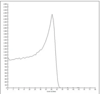
The Bragg peak in the 62 MeV proton beam simulation with incidence of 1.00 × 10⁶ protons without modulation, was re-produced. In such a case, a collimator with final diameter of 5.0 mm and 6.00 mm of absorbing material were applied, with at left of the center of eye lens in the voxel model. Figure 6 illustrates such peak. Such a simulation resulted in a maximum depos-ited dose of 5.59 GyE/p. The Bragg peak range was 23.0 mm, present in 0.5 mm3 voxels. A wider peak is observed as com-pared with the Bragg peak for carbon ion beam, as shown on Figure 1.
DISCUSSION
The irradiation process and dosimetric parameters applied in the simulations of carbon ion or proton therapy are compat-ible with those reported in the literature(1–
4,14). The intensities of the incident beams
and carbon ions currents were defined so that the clinical dose for the treatment of uveal melanoma (70 GyE – five sessions of 14 GyE) is achieved.
In the studies developed by Koyama-Ho et al.(3) and Tsuji et al.(4) of the Research Center Hospital for Charged Particle Therapy, National Institute of Radiological Sciences (NIRS), Chiba, Japan, patients with uveal melanoma were submitted to carbon ion therapy, with doses of 60, 70, 77 and 85 GyE in five fractions, according
to tumor size, visual acuity and distance from the optic disc(3,4). These authors have investigated the carbon ion therapy and utilized an incident kinetic energy of 140 MeV/u, considering the complete configu-ration of the passive beam delivery system, which comprises, among other compo-nents, a modulation system and absorbing Figure 4. Isodose curve superimposed on the eye model, generated in the
Siscodes, corresponding to the simulation performed without modulation of the 62 MeV proton beam, final collimator diameter of 5.0 mm and 8.0 mm of ab-sorbing material. Beam displacement of 5.0 mm at right from eye lens center.
Figure 5. Isodose curve superimposed on the eye model, generated in the Siscodes, corresponding to the simulation performed without modulation of the 62 MeV proton beam, final collimator diameter of 5.0 mm and 6.0 mm of absorbing material. Beam displacement of 7.0 mm at left from eye lens center.
materials for modulation and degradation of the beam energy. In the present study, energies of 744 MeV (62 MeV/u) to 1,080 MeV (90 MeV/u) were utilized, lower than the energy of 140 MeV/u, based on the char-acteristics of the computational configura-tions of the eye model(8) and of the irradia-tion line(10), where the devices for ion beam modulation and degradation were not acti-vated because of limitations of the distance between the carbon ion source and the tar-get. The beam intensity and carbon ion cur-rent applied in the present simulation were comparable to those applied at the NIRS, in order to achieve an equivalent clinical dose for the treatment of uveal melanoma (60 GyE – four sessions of 15 GyE)(14).
In a study developed at Centro di Adro-Terapia e Applicazioni Nucleari Avanzate, in Italy, Cirrone et al.(14) have reported the treatment of ocular tumors with proton therapy. A total of 47 patients presenting with uveal melanoma were submitted to treatment with protons, with applied dose of 60 GyE in four fractions.According to Cirrone et al.(10), 60% of their patients had T3 lesions(2). The dose levels define the current and intensity of the irradiation beam. Similarly, both parameters were equivalent to those investigated in the pro-ton simulations.
According to Table 2, in the simulations with carbon ions one observes that even maintaining a constant beam incidence, the maximum absorbed dose is not directly proportional to the kinetic energy of the incident particle. It varies with the incident kinetic energy of the particle and with the number of particles. In the simulations, a carbon beam with kinetic energy of 840 MeV (70 MeV/u) produced a greater dose deposited per voxel, considering the
inci-dence of 1.0 × 10⁴ carbon ions. Thus, a smaller number of incident carbon ions and current will be necessary to reproduce a therapeutic fraction of 14 GyE, optimizing the utilization of the facilities resources. On their turn, the values regarding maximum deposited doses, number of incident carbon ions and applied current varied by approxi-mately 24%, between maximum and mini-mum values for each parameter, while the difference between the lowest and highest values of kinetic energy of the incident beam varied by 31%.
The depth of the Bragg peak produced by carbon ion beams, as well as by proton beams, depends on the initial energy of the particle in the beam. For carbon ions, the range varied from 11 to 21.5 mm. Such fact is relevant in both situations, as the posi-tion of maximum absorbed dose can be adjusted by an external physical parameter independent from the tumor anatomy and biology, but dependent on the kinetic en-ergy of the incident particle. One can say that the physical parameters presented in this study define the operational range of carbon ion therapy in the therapeutic pro-tocols.
In the simulations with carbon ion beams, the variation of the kinetic energy of the incident particles was utilized to achieve different depths, while in the simu-lations with proton beam, an absorbing material was utilized to degrade the beam energy.
The processing time in the simulations ranged from 4 hours and 17 minutes to 8 hours, depending on the utilized energy. It is observed that heavy ion radiotherapy planning demands a high computational cost.
According to Table 3, the range of the protons beam varies with the thickness of the absorbing material, achieving a varia-tion of 20.5 to 23.0 mm. For the perfor-mance of the simulations with proton beams, the thicknesses of the absorbing materials were 6 mm and 8 mm, but, in clinical applications(14) the location and dimensions of the target volume must be considered for a correct configuration of such parameter. Thus, for each clinical case the variation of the absorbing material thickness must be defined for each particle beam entrance position.
The maximum deposited doses, main-taining the same number of incident pro-tons and the applied current, varied accord-ing to the thickness of the absorbaccord-ing mate-rial. The thicker the absorbing material, the lower the absorbed dose; thus, in order to maintain the recommended dose constant independently from depth, the exposure time must increase with the thickness of the absorbing material.
In the presented simulations, the num-ber of processed particles for carbon ions was 100 times smaller than that for
pro-tons(12). The mean values for maximum doses were 1.23 × 10⁻⁵ lower for protons in relation to the carbon ion beam, because of the higher value of the carbon ions charge and mass, which, consequently, cause greater ionization in their interaction. Thus, in clinical applications, additional 3 × 10⁵ incident particles and 4 × 10⁴ nA of current are necessary for protons as com-pared with carbon ion beam.
For simulations performed with inci-dent beam energy of 62 MeV/u, the range for carbon ions was 11 mm and, for pro-tons, 23 mm and 20.5 mm, for 6 mm and 8 mm of absorbing material, respectively. One considers that incident energy ≥ 90 MeV/u should be applied for carbon ions to achieve the same depth achieved with 62 MeV/u for protons.
CONCLUSION
The parameters utilized in the simula-tions, such as incident kinetic energy of the particles, current, absorbing material, modulator and collimator have aided in the characterization of the absorbed depth dose profile in the eyeball for proton and carbon ion beams. The characterization of such physical parameters is essential in the ra-diotherapy planning following the geomet-ric distribution of the target volume.
The integration of the software tools in different computational environments, in-volving the Geant4 code and its applica-tion libraries, together with the Siscodes, can be useful in the evaluation of ion tele-therapy plannings and contribute for future studies approaching dosimetry in carbon ion and proton radiotherapy. The findings of the present study contribute to the de-velopment of clinical applications and re-search in carbon ion and proton radio-therapy.
REFERENCES
1. Amaldi U, Kraft G. Radiotherapy with beams of carbon ions. Rep Prog Phys. 2005;68:1861–82. 2. Sobin LH, Wittekind Ch. TNM classification of malignant tumours. 6th ed. New York, NY: Wiley-Liss; 2002.
3. Koyama-Ito H, Kanai T, Minohara S, et al. Car-bon ion therapy for ocular melanoma: planning orthogonal two-port treatment. Phys Med Biol. 2007;52:5341–52.
dose-escalation study. Int J Radiat Oncol Biol Phys. 2007;67:857–62.
5. Tsujii H, Kamada T, Baba M, et al. Clinical ad-vantages of carbon-ion radiotherapy. New J Phys. 2008;10.
6. U.S. National Library of Medicine. The visible human project. [cited 2008 Nov 17]. Available from: http://www.nlm.nih.gov/research/visible 7. Trindade BM, Campos TPR. Sistema
computa-cional para dosimetria de nêutrons e fótons ba-seado em métodos estocásticos aplicado a radio-terapia e radiologia. Radiol Bras. 2011;44:109– 16.
8. Mourão AP, Campos TPR. Considerações radio-dosimétricas da braquiterapia ocular com
iodo-125 e rutênio/ródio-106. Radiol Bras. 2009;42: 43–8.
9. Christóvão MT, Campos TPR. Análise da distri-buição espacial de dose absorvida em próton te-rapia ocular. Radiol Bras. 2010;43:249–54. 10. Cirrone P, Cuttone G, Di Rosa F, et al. The
hadron-therapy Geant4 advanced example. In: 4th Work-shop on Geant4 Bio-medical Developments, Geant4 Physics Validation. 2005 July 13–20; Genova, Italy.
11. National Council on Radiation Protection and Measurements. Report No. 144 – Radiation Pro-tection for Particle Accelerator Facilities. Bethesda, MD: National Council on Radiation Protection and Measurements; 2003.
12. Ondreka D, Weinrich U. The Heidelberg ion therapy (HIT) accelerator coming into operation. Proceedings of EPAC08:979–81; Genoa, Italy. 13. Endo K, Fang Z, Fukumoto S, et al. Compact
pro-ton and carbon ion synchrotrons for radiation therapy. Proceedings of EPAC 2002:2733–5; Paris, France.
14. Cirrone GAP, Cuttone G, Lojacono RA, et al. A 62-MeV proton beam for the treatment of ocular melanoma at Laboratori Nazionali del Sud-INFN. IEEE Transactions on Nuclear Science. 2004;51: 860–5.