1
Microstructure and mechanical properties of gas tungsten arc welded
Cu-1Al-Mn shape memory alloy rods
2J. P. Oliveira 1, *, B. Crispim 1, Z. Zeng 2, T. Omori 3, F. M. Braz Fernandes 4, R. M. Miranda 1
3
1
UNIDEMI, Departamento de Engenharia Mecânica e Industrial, Faculdade de Ciências e
4Tecnologia, Universidade NOVA de Lisboa, Caparica, Portugal 5
2 School of Mechanical and Electrical Engineering, University of Electronic Science and
6
Technology of China, China 7
3 Department of Materials Science, Graduate School of Engineering, Tohoku University, Japan
8
4 CENIMAT/i3N, Materials Science Department, Faculdade de Ciências e Tecnologia,
9
Universidade NOVA de Lisboa, Campus de Caparica, 2829-516 Caparica, Portugal 10
* corresponding author: [email protected] 11
Abstract
12Large diameter rods of Cu-Al-Mn shape memory alloy were gas tungsten arc welded. The 13
microstructural evolution was studied by electron microscopy techniques and its impact on the 14
mechanical and functional response of the welded joints was assessed. The fusion zone 15
exhibited a mixture of α and β phases, while the base material was composed only by the parent 16
β phase. The refined grain structure of the fusion zone increased the material ductility and 17
greatly improved the functional fatigue resistance of the welded joint when compared to the 18
original base material. 19
Keyworks: Shape memory alloys; characterization; phase transformations; welding; 20
superelasticity; functional fatigue. 21
2
Graphical abstract
22 231. Introduction
24Shape memory alloys are part of a class of smart materials systems with unique properties. As 25
described in a comprehensive review paper (Otsuka and Ren, 2005) the shape memory and 26
superelastic properties of shape memory alloys makes these materials adequate for potential 27
applications in a wide variety of sectors such as medical, aerospace, civil engineering and 28
automotive. Currently, NiTi shape memory alloys have its use well widespread owing to stable 29
functional properties. Nonetheless, in recent years several exciting developments have been 30
emerging with the introduction of new classes of shape memory alloys. For example, Tanaka et 31
al. (2010) presented a Fe-based polycrystalline shape memory alloy with a total superelastic 32
strain of 13.5%, largely surpassing that of NiTi. More recently, Oliveira et al. (2018) presented a 33
monocrystalline Cu-based shape memory alloy which present a superelastic strain recovery up 34
to 30 % for a temperature range from -40 to + 100 °C. 35
Among these recent developments, Cu-based shape memory alloys have been attracting 36
significant attention as a result of better microstructural control during alloy production which 37
enhances their mechanical properties. Sutou et al. (2008) showed that the ratio between the 38
grain size, d, and the wire diameter, D, is of paramount importance to control the superelastic 39
and shape memory properties of Cu-Al-Mn alloys. In fact, when the d/D ratio increases the 40
superelastic recovery increases. Additionally, Cu-based alloys have lower production costs and 41
higher thermal and electrical conductivity than the widely used NiTi. 42
Based on the currently reported properties, the Cu-Al system is the most relevant one. Cu-Al-43
Be and Cu-Al-Mn shape memory alloys have presently the best mechanical properties within 44
Cu-based alloys. However, the presence of Be in Cu-Al-Be renders impossible its use in 45
3
biomedical applications and thermomechanical processing of such alloys must be performed 46
with precaution to avoid health issues. The same does not occur for Cu-Al-Mn alloys, where its 47
biocompatibility allows its use in biomedical devices. For example, Sutou et al. (2004) already 48
described that this alloy is currently used as a medical guidewire. 49
When it comes to the use of advanced engineering materials, at some point, the use of 50
welding and joining techniques will be required to expand their potential applications by 51
allowing more freedom of design or to couple their mechanical/functional properties with 52
other relevant materials. For this reason, development of appropriate joining techniques and 53
methodologies for these advanced materials is fundamental. 54
The development of joining technologies for shape memory alloys has been mainly devoted to 55
NiTi. These efforts used fusion-based methods, such as laser welding and resistance welding, 56
but also solid-state ones, such as impact welding and friction stir welding. Bahador et al. 57
(2017) used laser welding to join NiTi and found that a recovery strain up to 83% of that of the 58
base material could be achieved by the welded joint. The need for appropriate heat 59
treatments to be applied in resistance welded NiTi joints was evidenced by Delobelle et al. 60
(2013), showing that proper selection of post-weld heat treatments can lead to similar 61
transformation characteristics between the fusion zone and original base material. For 62
dissimilar joining involving NiTi, solid state techniques are usually preferred. Impact butt 63
welding was used by Li and Zhu (2018) to join NiTi to stainless steel and it was observed that 64
the impact speed was a critical welding parameter to optimize the mechanical properties of 65
the joints. Finally, friction stir welding was applied by Oliveira et al. (2017a) to successfully join 66
NiTi to Aluminium and the presence of martensite in the joint after welding was attributed to 67
Ni-rich precipitation which locally changed the transformation temperatures of the material. 68
As it can be inferred from the examples presented before, welding and joining of other shape 69
memory alloys systems, including Cu-based alloys, is still in the early stages of development 70
with only few reports on welding attempts and its impact on the microstructure and 71
mechanical properties, currently available. Laser welding has been previously used to join Cu-72
based shape memory alloys in both similar and dissimilar combinations. Laser welding of Cu-73
Zn-Al foams was attempted by Biffi et al., (2016) and the martensitic transformation was 74
preserved after welding. Laser microwelding of Cu-Al-Mn to NiTi was performed by Oliveira et 75
al. (2017b) and it was observed that, despite the complex microstructure generated in the 76
fusion zone, superelastic behaviour was obtained in the welded joint. These recent results, 77
evidence the excellent weldability of these materials when laser welding was employed. 78
However, laser welding is not necessarily the most appropriate joining technique when 79
4
welding of large diameter/thickness materials is necessary. In fact, when the 80
diameter/thickness of the material to join increases, a finer control of the processing 81
parameters is required to avoid welding defects as evidenced by Pang et al. (2014) in their 82
studies on keyhole laser welding. Arc-based welding techniques can be less prone to pore 83
formation, especially in the gas tungsten arc welding process (or tungsten inert gas). This 84
technique has been already used by Torbati et al. (2011) to achieve high quality joints, despite 85
the lower production rates compared to laser welding. Additionally, recent results presented 86
by Oliveira et al. (2016) showed that gas tungsten arc welding is a promising technique for 87
joining of shape memory alloys. 88
In this work, gas tungsten arc welding was used to join large diameter Cu-Al-Mn shape 89
memory alloy rods. The microstructural evolution, mechanical and functional properties of the 90
joints were studied by means of microscopy techniques and mechanical testing. The 91
optimization of gas tungsten arc welding for these materials may expand their range of 92
applications in structural devices, such as energy absorption mechanisms. 93
2. Materials and methods
942.1. Materials
95
Superelastic Cu-17Al-11.4Mn (at. %) rods were used. The base material was prepared as 96
reported in (Sutou et al., 2005). Differential scanning calorimetry measurements performed on 97
the as-received base material confirmed a fully austenitic alloy at room temperature. 98
2.2. Gas Tungsten Arc Welding
99
A welding machine from TELWIN, model Technology TIG 182 AC/DC-HF/LIFT was used for gas 100
tungsten arc welding. Since this is the first study on arc welding of these materials, orbital 101
bead-on-plate welds were produced. Such reduces the variability of joint-fit up, allowing to put 102
more emphasis on the microstructural evolution and its impact on the mechanical properties 103
of the joints. 104
Welds were performed using direct current and straight polarity aiming at achieving full 105
penetration and absence of defects. Argon was selected as shielding gas and the flow rate was 106
kept constant at 10 L/min, which ensured an oxidation-free weld by visual inspection. The 107
optimized welding parameters comprised a welding/rotation speed of 7.5 mm/s (or 12 rpm) 108
and a welding current intensity of 38 A, which corresponded to a welding voltage of 11.5 V. 109
5
The material surface oxide layer was removed before welding using SiC paper and the rods 110
were cleaned with ethanol, so that any impurities that could interfere with the weld would be 111
eliminated. 112
2.3. Microstructural characterization
113
After welding the joint cross section was prepared for metallographic analysis by means of 114
mechanical polishing and etching. Optical microscopy was performed using a Leica DMI5000 M 115
microscope. 116
A Zeiss Auriga scanning electron microscope (SEM) was used for a more thorough 117
understanding of the microstructural evolution in the welded specimen. Furthermore, energy 118
dispersive spectroscopy (EDS) was used to assess the homogeneity of the chemical 119
composition in both the fusion zone and the heat affected zone of the welds. 120
The crystallographic orientation and existing phases throughout the welded joints were 121
determined by Electron Back-Scattered Diffraction (EBSD). 122
X-ray diffraction analysis was performed on the fusion zone of a welded specimen to identify 123
and characterize the phases present at room temperature. A Brucker diffractometer with 124
conventional θ/2θ scanning was used. 125
Hardness measurements on the weld cross section were performed to identify softening or 126
hardening effects promoted by the welding process. A Mitutoyo HM-112 microhardness tester 127
was used, and a test load of 200 g was applied for 10 seconds. A total of seventeen hardness 128
measurement lines were performed, with indentations distancing 200 μm horizontally and 129
100 μm vertically. From these measurements a bidimensional (x, y) hardness map was 130
constructed to evaluate the microhardness changes across the fusion zone up to the non-131
affected base material. 132
2.4. Mechanical testing
133
Uniaxial tensile testing of the base and welded material was performed using an Autograph 134
Shimadzu AG50kNG machine. The displacement rate was of 1 mm/min and the tests were 135
performed at room temperature. To eliminate potential gripping problems, the cylindrical 136
specimens were machined to a reduced cross section with 4 mm diameter, with the samples 137
having a gauge length of 30 mm. The fracture surfaces were analysed by SEM to determine the 138
failure mode in both base material and welds. 139
Mechanical cycling of the welded and non-welded specimens was performed to evaluate the 140
functional fatigue. Testing procedure consisted on straining the material to 8% followed by 141
6
unloading to a zero-stress condition. This was repeated for a total of 100 cycle using a 142
displacement rate equal to that of the uniaxial tensile tests. From the load/unload testing, the 143
evolution of irrecoverable strain, absorbed energy and maximum stress with the number of 144
cycles was determined. 145
3. Results and discussion
1463.1. Microstructural evolution
147
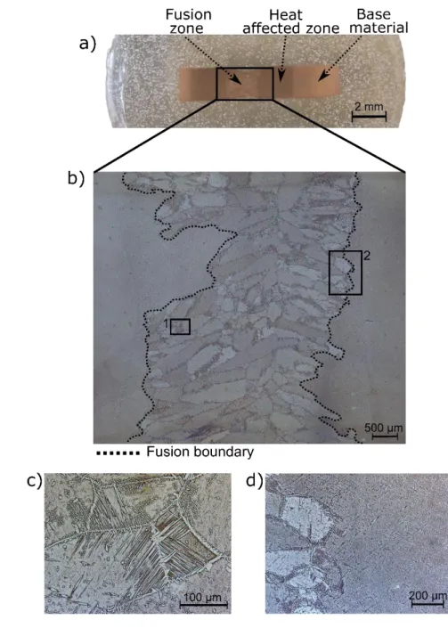
Figure 1 depicts the microstructure of the welded specimen. A full penetration joint, absent of 148
welding defects such as pores or cracks, was obtained. Optical microscopy showed the single 149
crystal base material and revealed that the fusion zone presents a coarse grain structure, 150
where the grain size ranged from 70 μm to 1.4 mm (Figure 1 a and b). In the fusion zone, 151
columnar grains are observed, which result from grain growth starting on the pre-existing solid 152
material on the fusion boundary, where the thermal gradient is more severe as described by 153
Kou (2002) and develops perpendicularly to the isothermal lines, parallel to the heat flow 154
direction, growing towards the weld centreline where the heat flow decreases. The non-155
symmetrical fusion zone geometry arises from the fact that the as-received rods where slightly 156
warped along their length leading to local arc instabilities during welding. Nevertheless, these 157
local instabilities did not cause any welding defects in the joints. 158
Precipitation phenomena of a new phase was observed in the heat affected and fusion zones, 159
as depicted in Figure 1 c and d, respectively. This phase nucleated at the grain boundaries of 160
the prior β-phase (body-centred cubic), showing needle shaped-like structures in the grain 161
boundaries and within each grain. In some regions, this acicular morphology showed different 162
sizes and shapes, while in other regions a more regular structure was observed with a 163
Widmanstätten-like morphology inside the grains (Figure 1 c). Widmanstätten structures have 164
previously been observed in Cu-based shape memory alloys as described by Bujoreanu (2008) 165
when evaluating the effect of austenitization on Cu-Zn-Al alloys. Widmanstätten needles form 166
in the β-phase of the material that has been cooled across the β/(α (face-centred cubic)+β) 167
phase boundary. This particular grain morphology occurs due to the low cooling rates induced 168
by high arc energy processes, such as in gas tungsten arc welding. 169
7 170
Figure 1 – a) Macrograph of the welded joint; b) detail of the fusion zone highlighting the two regions of
171
interest; c) region “1” showing a high magnification image of fusion zone grains; d) region “2” showing a
172
detail of the heat affected zone/fusion zone interface.
173
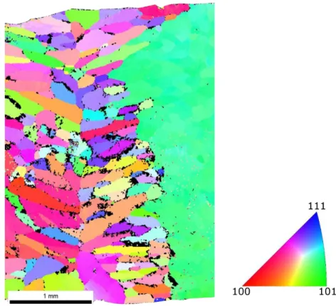
For Cu-Al-Mn alloys, Sutou et al. (2005) previously evidenced that the grain colour differences 174
observed by optical microscopy are related to changes in grain orientation. Therefore, fusion 175
zone coloration suggests the existence of a grain structure with continuously changing 176
orientation. EBSD was used to determine the grain orientation within the fusion zone and to 177
identify the existing phases. Figure 2 depicts the inverse pole figure orientation map of the 178
welded joint obtained by EBSD. The colours of each grain in the microstructure indicate their 179
crystallographic orientation, along the longitudinal direction, according to the stereographic 180
triangle. EBSD observations allowed the confirmation of the previous results (based only on 181
8
colorimetric changes observed by optical microscopy). That is, the welded zone and the initial 182
base material crystals have different grain orientations, where it can be observed that the 183
grains present different colours and, consequently, different orientations. The columnar grains 184
do not seem to have a preferential orientation; thus, the welding procedure does not impose a 185
well-defined texture in the fusion zone. Since the superelastic recovery in single crystal shape 186
memory alloys is highly dependent on the loading direction and grain orientation, texture 187
control is typically important for improving and preserving their superelastic properties. In 188
particular, Sutou et al. (2004) demonstrated that for Cu-Al-Mn wires, the existence of a <110> 189
fibre texture generated a higher yield stress and transformation strain when compared to a 190
random texture. 191
192
Figure 2 – EBSD Inverse Pole Figure orientation map of the welded joint.
193
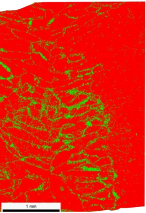
Phase identification by EBSD depicted in Figure 3 also revealed that the fusion zone was mainly 194
constituted by the parent β-phase, while precipitation of α occurred along the grain 195
boundaries and near the fusion zone boundary due to the slow cooling rate experienced 196
during welding. 197
9 198
Figure 3 – EBSD phase identification: red – parent β-phase; green – α-phase.
199
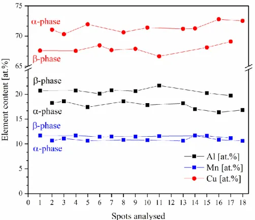
The compositional variation of the distinguishable phases after the welding process was 200
determined by EDS analysis. The aim was to determine if the formation of the α-phase was 201
accompanied by a chemical composition change. 202
EDS measurements performed on the α and β-phases clearly reveal compositional changes 203
between the two phases. In comparison to the base material, the remaining β matrix, has a 204
higher Al and Mn content, due to the precipitation of the α-phase, which is richer in Cu. 205
Guilemany and Fernández (1996) have made similar observations for Cu-Zn-Al-Co shape 206
memory alloys. The changes in composition resulting from EDS measurements performed at 207
18 different locations in the β and α-phases are depicted in Figure 4, and the major difference 208
between the two phase is the Cu content. 209
10 210
Figure 4 – Compositional profile across the fusion zone in the α and β-phase regions.
211
An X-ray diffraction pattern of the fusion zone is depicted in Figure 5. Diffraction peaks of both 212
β and α-phases were observed in good agreement with the EBSD data, confirming that the 213
weld metal is composed bya biphasic structure of β and α-phases. 214
215
Figure 5 – X-ray diffraction pattern of the fusion zone of the welded joint.
11
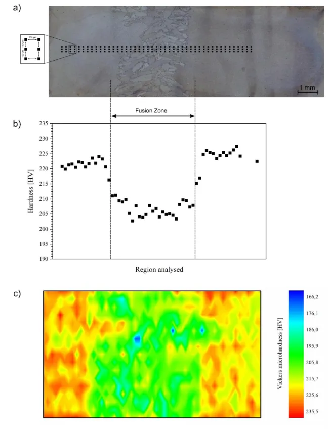
Hardness measurements were performed throughout the material as schematically presented 217
in Figure 6 a). A representative trend of the average hardness results of the regions analysed is 218
depicted in Figure 6 b). Significant differences in hardness were found between the fusion 219
zone (≈ 207.1 ± 10.9 HV) and the base material (223.9 ± 5.9 HV), suggesting that slow cooling 220
experienced by the fusion zone and the presence of α-phase contribute to a softening effect 221
similar to what was reported by Tuissi et al. (1999) for NiTi welded joints. 222
The inability to detect hardness variations in the heat affected zone of the joint may be 223
attributed to the heat treatments performed before welding to induce the bamboo-like 224
structure in the as-received material. A recent work on laser welding of Cu-Al-Mn performed 225
by Oliveira et al. (2016b) has shown the same difficulty. Solely near the fusion zone boundary, 226
a considerable variation of values is detected, which can be attributed to the presence of α-227
phase near this region. The symmetric trend of the hardness measurements both on the right 228
and on the left of the welded zone confirms the repeatability of the results. 229
Figure 6 c) presents the microhardness map of the similar Cu-Al-Mn joint. A good match with 230
the macrograph depicted in Figure 6 a) is clear, showing that in the fusion zone the hardness 231
values are relatively lower, of about ≈15 HV, than in the remaining regions. 232
12 233
Figure 6 – a) Macrograph of the welded specimen showing the schema for hardness measurements; b)
234
average hardness results for the region analysed; c) hardness mapping of the complete joint.
235
3.2. Mechanical properties
236
Room temperature tensile testing was performed on both the as-received material and welded 237
joints, to evaluate their mechanical properties. Figure 7 depicts the corresponding stress-strain 238
curves obtained at room temperature and several similarities between the base material and 239
13
welded joints are observed. For example, the stress required for the stress induced martensitic 240
transformation occurs at approximately 250 MPa in both weld and unwelded conditions. For 241
this class of shape memory alloys, the stress onset for the superelastic plateau is dependent on 242
texture and/or loading direction. In fact, within the gauge length of the specimens used for 243
tensile testing the number of grains which are being strained may vary. Since these alloys have 244
a very large grain size, any minor variation of the number of available grains from the base 245
material within the gauge length can significantly alter their mechanical properties. Elongation 246
to fracture values are higher in all the welded specimens, when compared to those of the base 247
material, with fracture occurring at strain levels of 31 and 38% for the welded joints, where the 248
base material fractured at 25 % strain. 249
Typically, when welding shape memory alloys, for instance NiTi, the grain growth observed in 250
the thermally affected regions is recognized to impair the mechanical resistance of the joint as 251
described by Gugel et al. (2008). That is not the case for the material used in this study, since 252
similar mechanical properties were observed in both the base material and welded joint. This 253
can be attributed to the high temperature heat treatments used to induce the generally large 254
grain size in the material. 255
During tensile testing of the base material, significant necking was observed in the central 256
region of the specimen where fracture occurred. Remarkably, the fracture location in the 257
welded joints was in the base material, distant from the fusion zone. In fact, during tensile 258
testing necking of two regions in the base material was observed, as depicted in Figure 8, 259
which are represented in the snapshots (from t1 to t4), taken during tensile testing. Necking
260
occurred only in the base material, while no localized deformation occurred in the fusion zone 261
of the weld. Eventually, fracture of the welded joint occurred. This is related with the relatively 262
finer grain structure in the welded region. For Cu-Al-Mn alloys the work of Sutou et al. (2005) 263
showed that a decrease in grain size, as it occurs in the fusion zone, promotes a rise of the 264
stress necessary to induce austenite to martensite transformation. Therefore, after welding, 265
the imposed deformation is primarily accommodated by the single crystal-like base material. 266
As such, even though the fusion zone will start to be plastically deformed, as evidenced by the 267
t4 snapshot in Figure 8, the base material will eventually promote the formation of cracks
268
because of the massive plastic deformation already experienced in this region. Such 269
deformation promotes the formation of cracks in the base material and these propagate in an 270
almost unobstructed path owing to the lack of grain boundaries, as those existing in the fusion 271
zone. On the other hand, the existence of a single crystal-like microstructure in the base 272
material, will not be effective in stopping or delaying the progress of any cracks that are 273
14
formed in this region. This explains the increased ability of the welded joint to deform until 274
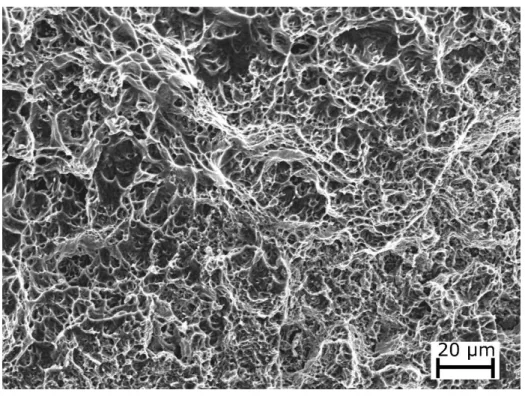
fracture. SEM imaging after tensile testing of the base material and welded specimens clearly 275
reveals dimples along the fracture surface (Figure 9), which is characteristic of a ductile-like 276
fracture mode in good agreement with the extensive deformation that the material was able 277
to sustain before fracture occurred. 278
279
Figure 7 – Tensile behaviour of the Cu-Al-Mn base material and welded specimens.
280
281
Figure 8 – Evolution of the reduced cross section during tensile testing of the gas tungsten arc welded
Cu-282
Al-Mn shape memory alloy. t1 (before any deformation occured) < t2 < t3 < t4 (fracture instant), with t1 283
and t4 corresponding to the conditions before tensile testing and after fracture of the specimen, 284
respectively.
15 286
Figure 9 – SEM image of the fracture surface of the welded specimen after tensile testing.
287
The increasing need for vibration and noise control is currently pushing for the development of 288
high damping capacity materials, such as shape memory alloys. To accommodate these needs, 289
it is required that the selected materials can absorb substantial amounts of energy, when 290
subjected to load variations, such as seismic devices. Therefore, the understanding of the 291
load/unload cycling behaviour of the joints and its repeatability is fundamental to evaluate the 292
viability of their use in such applications. For these materials, energy dissipation can be made 293
with the material in the austenitic or martensitic phase. However, it is typically preferred that 294
the material is in the austenitic domain prior to the solicitation, so that it can perform in the 295
superelastic regime. Ideally, during superelastic solicitation, the imposed deformation can be 296
completely recovered upon unloading, provided that the stress to induce dislocation slip is not 297
reached. Currently, as stated by Gencturk et al. (2014), Cu-Al-Mn alloys are being tested as 298
energy-absorption devices. 299
In the present study the welded joints and base material, for reference, were subjected to a 300
cycling routine to evaluate their superelastic properties, where the rods were loaded with a 301
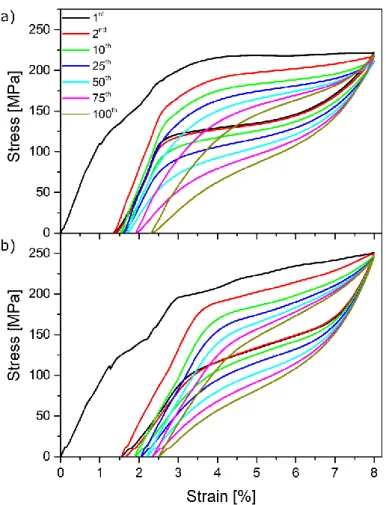
maximum imposed strain of 8%, followed by unloading to a zero-stress condition. Figure 10 a 302
and b) depicts some of the 100 load/unload cycles performed for both base and welded 303
materials, respectively. The start of the martensitic transformation occurs approximately at 304
the same values of the previous tensile tests. Furthermore, the superelastic curve typical of 305
these materials is clear in the welded joints. 306
16 307
Figure 10 – Cycling behaviour of: a) base material; b) welded joint.
308
Figure 11 depicts the evolution of the irrecoverable strain, absorbed energy and maximum 309
stress during loading with the number of cycles in both the base material and welded joint. 310
Slight differences in the cycling behaviours were observed. The base material had a lower 311
irrecoverable strain in the first complete cycle, of about 1.3%, whereas for the welded joint it 312
slightly increased to 1.5%. Multiple factors can affect the superelastic response of these 313
materials, namely grain size and/or grain orientation. In Cu-based shape memory alloys, the 314
irrecoverable strain during superelastic cycling depends on the ratio between the grain size (d) 315
and wire diameter (D), d/D, and is known to increase when the grain size becomes smaller. 316
More generally, for these materials, the superelastic strain and recovery increase with 317
increasing d/D. The higher irrecoverable strain in the welded joint can, therefore, be ascribed 318
to the refined grain microstructure developed in the fusion zone, which has a smaller d/D ratio 319
than the as-received material thus, reducing the superelastic recovery. Another reason that 320
can justify the higher irrecoverable strain is related to the presence of α-phase, which does not 321
contribute to the superelastic behaviour. For Cu-Al-Mn alloys the grain orientation is critical for 322
their superelastic performance. While the base material had a well-defined texture, which 323
maximizes its superelastic behaviour, the development of a near random texture in the fusion 324
17
zone is not actively contributing to a significant increase in the irrecoverable strain during 325
superelastic cycling. Previous work on the effect of crystallographic orientation on the 326
functional properties of these alloys performed by Sutou et al. (2004) has shown that a 327
random texture yields an irrecoverable strain of 0.2% when strained up 6%. Therefore, it can 328
be concluded that the irrecoverable strain observed in the welded samples can be mainly 329
attributed to the refined grain structure in the fusion zone. 330
Of special interest is the evolution of the accumulated irrecoverable strain with the number of 331
cycles (Figure 11 top). For the joint, the irrecoverable strain has a steady increase after only 25 332
mechanical cycles. In opposition, for the base material after 60 load/unload cycles a sharp 333
change in the evolution of the irrecoverable strain was observed. 334
Such has consequences on the functional fatigue behaviour of materials. As defined in the 335
work of Eggeler et al. (2004), functional fatigue is related to how a given functional property 336
(superelasticity and/or shape memory effect for shape memory alloys) decreases during 337
consecutive solicitations. Functional fatigue should not be confused with structural fatigue 338
which indicates the number of cycles that the material can suffer prior to failure under a given 339
stress or strain amplitude. 340
In this work, the functional fatigue of the base material tends to be more important than in the 341
weld after a given number of cycles, since the intersection between the two curves would 342
occur at around 110 cycles, after which the irrecoverable strain of the base material would 343
surpass that of the welded joint (Figure 11 a). This unusual behaviour can be explained based 344
on the microstructural evolution in the welded material. The small grain size of the fusion zone 345
contributes to this effect in two distinct ways: a strain-hardening in the welded joint combined 346
with a decrease of the Ms and Af transformation temperatures with decreasing grain size
347
resulting in a higher stress for the start of the austenite to martensite transformation and a 348
higher Md temperature, giving a wider “superelasticity window”; since the number of grain
349
boundaries in the base material is necessarily lower than in the fusion zone, with only one to 350
five grain existing in that region of the specimen during mechanical cycling, the movement of 351
dislocations in the material during mechanical solicitation is less restrained which results in 352
lower resistance to functional fatigue under the tested conditions. 353
In Figure 11 b), it can also be observed that the higher absorbed energy by both as-received 354
material and welded joint occurs in the first load/unload solicitation due to the lower 355
superelastic recovery. After the first complete cycle, the hysteric loop starts to stabilize. The 356
18
welded joint has a slightly higher capacity for energy absorption due to the microstructural 357
refinement of the fusion zone. 358
Finally, the maximum stress during loading of both base material and welded joint is presented 359
in Figure 11 c). The welded joint has a consistently higher maximum stress, arising again from 360
the microstructural changes observed in the fusion zone, which cause a slight increase on the 361
stress to induce the martensitic transformation. 362
363
Figure 11 – Evolution of the accumulated irrecoverable strain (top), absorbed energy (middle) and
364
maximum stress (bottom) with the number of cycles for the base material and the welded specimen.
19
4. Conclusions
366
The microstructural evolution of gas tungsten arc welding of Cu-Al-Mn shape memory alloys 367
was assessed and correlated to the mechanical and functional properties of the joints. The 368
main conclusions of this work are as follows: 369
- The welding procedure promoted grain refinement and the development of near-random 370
crystallographic texture in the fusion zone. 371
- Precipitation phenomena of α-phase was observed in the fusion and heat affected zones 372
due to the slow cooling upon arc extinction. 373
- The welded joints had a significantly higher ductility than the base material owing to the 374
refined grain structure of the fusion zone. 375
- The material superelastic properties were kept after welding, with the joints exhibiting a 376
superelastic recovery of nearly 6.5% for a maximum imposed strain of 8% in the first 377
load/unload cycle. 378
- The functional fatigue resistance of the material, under the conditions tested, was 379
improved after welding owing to the fine-grained fusion zone which difficult dislocation 380
movement during superelastic cycling. 381
Acknowledgments
382JPO, BC and RMM acknowledge Fundação para a Ciência e a Tecnologia (FCT - MCTES) for its 383
financial support via the project UID/EMS/00667/2019. FMBF acknowledges funding by FEDER 384
through the program COMPETE 2020 and National Funds through FCT-Portuguese Foundation 385
for Science and Technology, under the project UID/CTM/50025/2013. ZZ acknowledges the 386
National Natural Science Foundation of China (Grant No. 51775091) and the Science and 387
Technology Planning Project of Sichuan Province (Grant No. 2018GZ0284). 388
References
389Bahador, A., Hamzah, E., Kondoh, K., Kawahito, Y., Junko, U., Bakar, T.A.A., 2017. Mechanical 390
and superelastic properties of laser welded Ti–Ni shape-memory alloys produced by 391
powder metallurgy. J. Mater. Process. Technol. 248, 198–206. 392
https://doi.org/10.1016/j.jmatprotec.2017.05.019 393
Biffi, C.A., Previtali, B., Tuissi, A., 2016. Microstructure and calorimetric behavior of laser 394
welded open cell foams in CuZnAl shape memory alloy. Funct. Mater. Lett. 9, 1642007. 395
https://doi.org/10.1142/S1793604716420078 396
20
Bujoreanu, L.G., 2008. On the influence of austenitization on the morphology of α-phase in 397
tempered Cu-Zn-Al shape memory alloys. Mater. Sci. Eng. A 481–482, 395–403. 398
https://doi.org/10.1016/j.msea.2006.12.223 399
Delobelle, V., Delobelle, P., Liu, Y., Favier, D., Louche, H., 2013. Resistance welding of NiTi 400
shape memory alloy tubes. J. Mater. Process. Technol. 213, 1139–1145. 401
https://doi.org/10.1016/j.jmatprotec.2013.01.013 402
Eggeler, G., Hornbogen, E., Yawny, A., Heckmann, A., Wagner, M., 2004. Structural and 403
functional fatigue of NiTi shape memory alloys. Mater. Sci. Eng. A 378, 24–33. 404
https://doi.org/10.1016/j.msea.2003.10.327 405
Gencturk, B., Araki, Y., Kusama, T., Omori, T., Kainuma, R., Medina, F., 2014. Loading rate and 406
temperature dependency of superelastic Cu-Al-Mn alloys. Constr. Build. Mater. 53, 555– 407
560. https://doi.org/10.1016/j.conbuildmat.2013.12.002 408
Gugel, H., Schuermann, A., Theisen, W., 2008. Laser welding of NiTi wires. Mater. Sci. Eng. A 409
481–482, 668–671. https://doi.org/10.1016/j.msea.2006.11.179 410
Guilemany, J.M., Fernández, J., 1996. Relationships between structure and hardness developed 411
during the high temperature ageing of a smart Cu-based alloy. J. Mater. Sci. 31, 4981– 412
4984. https://doi.org/10.1007/BF00355890 413
Kou, S., 2002. Welding Metallurgy, 2nd ed. ed. John Wiley & Sons, Inc., Hoboken. 414
https://doi.org/10.1002/0471434027 415
Li, Q., Zhu, Y., 2018. Impact butt welding of NiTi and stainless steel- An examination of impact 416
speed effect. J. Mater. Process. Technol. 255, 434–442. 417
https://doi.org/10.1016/j.jmatprotec.2017.12.046 418
Oliveira, J.P., Barbosa, D., Fernandes, F.M.B., Miranda, R.M., 2016. Tungsten inert gas (TIG) 419
welding of Ni-rich NiTi plates: functional behavior. Smart Mater. Struct. 25, 03LT01. 420
https://doi.org/10.1088/0964-1726/25/3/03LT01 421
Oliveira, J.P., Duarte, J.F., Inácio, P., Schell, N., Miranda, R.M., Santos, T.G., 2017a. Production 422
of Al/NiTi composites by friction stir welding assisted by electrical current. Mater. Des. 423
113, 311–318. https://doi.org/10.1016/j.matdes.2016.10.038 424
Oliveira, J.P., Zeng, Z., Andrei, C., Braz Fernandes, F.M., Miranda, R.M., Ramirez, A.J., Omori, T., 425
Zhou, N., 2017b. Dissimilar laser welding of superelastic NiTi and CuAlMn shape memory 426
alloys. Mater. Des. 128, 166–175. https://doi.org/10.1016/j.matdes.2017.05.011 427
21
Oliveira, J.P., Zeng, Z., Berveiller, S., Bouscaud, D., Braz Fernandes, F.M., Miranda, R.M., Zhou, 428
N., 2018. Laser welding of Cu-Al-Be shape memory alloys: Microstructure and mechanical 429
properties. Mater. Des. 148, 145–152. https://doi.org/10.1016/j.matdes.2018.03.066 430
Oliveira, J.P., Zeng, Z., Omori, T., Zhou, N., Miranda, R.M., Fernandes, F.M.B., 2016. 431
Improvement of damping properties in laser processed superelastic Cu-Al-Mn shape 432
memory alloys. Mater. Des. 98, 280–284. https://doi.org/10.1016/j.matdes.2016.03.032 433
Otsuka, K., Ren, X., 2005. Physical metallurgy of Ti-Ni-based shape memory alloys. Prog. Mater. 434
Sci. 50, 511–678. https://doi.org/10.1016/j.pmatsci.2004.10.001 435
Pang, S., Chen, W., Wang, W., 2014. A quantitative model of keyhole instability induced 436
porosity in laser welding of titanium alloy. Metall. Mater. Trans. A Phys. Metall. Mater. 437
Sci. 45, 2808–2818. https://doi.org/10.1007/s11661-014-2231-3 438
Sutou, Y., Omori, T., Furukawa, A., Takahashi, Y., Kainuma, R., Yamauchi, K., Yamashita, S., 439
Ishida, K., 2004. Development of medical guide wire of Cu-Al-Mn-base superelastic alloy 440
with functionally graded characteristics. J. Biomed. Mater. Res. B. Appl. Biomater. 69, 64– 441
9. https://doi.org/10.1002/jbm.b.10079 442
Sutou, Y., Omori, T., Kainuma, R., Ishida, K., 2008. Ductile Cu–Al–Mn based shape memory 443
alloys: general properties and applications. Mater. Sci. Technol. 24, 896–901. 444
https://doi.org/10.1179/174328408X302567 445
Sutou, Y., Omori, T., Wang, J.J., Kainuma, R., Ishida, K., 2004. Characteristics of Cu-Al-Mn-based 446
shape memory alloys and their applications. Mater. Sci. Eng. A 378, 278–282. 447
https://doi.org/10.1016/j.msea.2003.12.048 448
Sutou, Y., Omori, T., Yamauchi, K., Ono, N., Kainuma, R., Ishida, K., 2005. Effect of grain size 449
and texture on pseudoelasticity in Cu-Al-Mn-based shape memory wire. Acta Mater. 53, 450
4121–4133. https://doi.org/10.1016/j.actamat.2005.05.013 451
Tanaka, Y., Himuro, Y., Kainuma, R., Sutou, Y., Omori, T., Ishida, K., 2010. Ferrous 452
Polycrystalline Shape-Memory Alloy Showing Huge Superelasticity. Science (80-. ). 327, 453
1488–1490. https://doi.org/10.1126/science.1183169 454
Torbati, A.M., Miranda, R.M., Quintino, L., Williams, S., Yapp, D., 2011. Optimization 455
procedures for GMAW of bimetal pipes. J. Mater. Process. Technol. 211, 1112–1116. 456
https://doi.org/10.1016/j.jmatprotec.2011.01.013 457
Tuissi, A., Besseghini, S., Ranucci, T., Squatrito, F., Pozzi, M., 1999. Effect of Nd-YAG laser 458
welding on the functional properties of the Ni–49.6at.%Ti. Mater. Sci. Eng. A 273–275, 459
22
813–817. https://doi.org/10.1016/S0921-5093(99)00422-0 460