DOI: ISSN: 2318-4531 Abstract— In this work we present a generalized theory of
galvanometers from the point of view of the dynamical equations of coils subjected to general (but homogeneous) time varying magnetic fields. We explore new inductive principles for driving and controlling galvanometers (whose modern versions take the form of scanners) and envisage a special frequency shift due to electromechanical coupling terms under the presence of a transversal magnetic field. Such frequency shift can be used to electronically control the resonance frequency of scanners. Numerical simulations are presented for a silicon microscanner.
Index Terms—sensor systems, electromagnetic induction, induction motors, micromotors, scanners, galvanometric scanners, inductance, voltage controlled oscillators.
I. INTRODUCTION
ecently there has been much interest in the microfabrication of light beam deflectors serving a variety of practical applications (laser printing, photo composition and laser projection) [1-5]. In other devices, such as Retinal Scanning Displays (RSD) [6], uniaxial or biaxial scanners are employed to perform raster scanning and project light beams directly onto the viewer’s retina. In many systems, an electrostatically actuated mirror [7][8] torsionally oscillates at a certain frequency providing an optical deflecting surface that can be electronically controlled. In other devices [9], also operating in torsional mode, an inertial mass is driven by the actuation of Lorentz force produced by the passage of currents in a circuit that is lithographed on the mass body. Typical resonance frequencies depend on the device size and high frequency applications depend on system miniaturization. ______________________________________________________________ Ademir L. Xavier jr is senior scientist at Wernher von Braun Advanced Research Center at Av. Alice de C. Pupo Nogueira Mattosinho, 301, Alphaville, 13098-392 Campinas-SP, Brazil (e-mail: [email protected])
Regarding electromagnetic actuation principles, one usually compares between purely electrostatic [10][11] against magnetic forces when electric currents are involved, but other principles also exist (fluidic, thermopneumatic [12][13], ultrasonic etc[14]). The galvanometric principle, for example, is able to successfully drive small light beam deflectors [3] using weak magnetic field intensities (< 0.5 T).
Advantages of magnetic actuation are: relatively long range, low input voltages and large displacements. In this paper, we will are mainly interested in a detailed description of the galvanometric actuation under space and time varying magnetic fields. The theoretical path [15][16] followed here may open new approaches [17] for electromagnetic actuation of microscanners serving a variety of purposes. One simple example is in the field of laser displays [8][18]. Since microscanners are relatively small devices by definition, field homogeneity is assumed throughout our treatment, which is the same of assuming that field gradients are small. This is an important simplifying assumption that set us free from having to calculate the exact current distribution of galvanometric coils due to field inhomogeneity. From the purely theoretically point of view, single axis galvanometers actuated by magnetic oscillating fields are nonlinear oscillators exhibiting a rich dynamics and a thorough understanding of such dynamics is relevant in the context of device control.
The organization of this paper is as follows: in Section II, we review the basic equations of a plate torsionally displaced by a single axis and carrying a current loop under the influence of general time varying magnetic fields. This may be called the general problem of galvanometers [2] which modernly appears in the form of magnetically actuated scanners. The galvanometric actuation principle is treated as a particular case of the general equations governing the electromechanical movement. In Section III we solve the general case subjected to parallel and transversal oscillating
Dynamics of Galvanometric Scanners under
Parallel and Transverse Magnetic Fields
Ademir L. Xavier Jr.
____________________________________________________________________________
DOI: ISSN: 2318-4531 (AC) fields using chosen parameters. As a practical
illustration, in Section IV we present numerical simulations using a silicon microscanner. We detail the oscillation mode driven by induction and discuss the resonance coupling due to the presence of constant (DC) electric currents for a torsional oscillator subjected to both transversal DC and parallel AC magnetic fields. Spectral analysis of the device time response shows a shift in the mechanical resonance frequency, which may be enhanced by changing the coil resistance. The resonance shift effect can be suitably used to control the frequency of oscillation in scanners.
II. FORMULATION OF THE PHYSICAL MODEL
A. The simple galvanometric oscillator
A plate (rotor) carrying a current loop oscillates about its z axis as shown in Fig.1. The deflection angle is the angle between y and the plate normal n. Two independent magnetic induction fields By and Bx, pointing toward the y (transverse)
and x (parallel) directions, respectively, are present in the region of the plate. Therefore, these components have independent origins. Let us first review here the basic dynamical equation for By = 0 (null transversal field), which
corresponds to the classic galvanometric oscillator. We allow however Bx to vary with time.
Fig. 1 Schematic drawing representing the plate rotor (oscillation about the z axis) and the coordinate reference system.
The plate is subjected to torque:
, ˆ
,
nB n (1) with the coil magnetic moment and nˆ a unitary vector normal to the plate as shown in Fig.1. If A is the coil area, then:
niABxcos
(2)
is the strength of the magnetic torque, with n the total number of coil turns. The rotor structure has moment of inertia J about z which is the only axis to be considered making the dynamics
one-dimensional. The rotor is suspended by two torsion bars such that the elastic torque has characteristic constant k. The mechanical equation for the rotor movement is therefore given by
k nAiBx diss J cos,
(3)where primes indicate time differentiation.
We remark that in Eq.3 the effect of air damping can be modeled by a dissipative term of the form:
...
diss a b,
(4)with a and b positive constants. Eq. 4 is an expansion of a function of the angular velocity only with linear and a nonlinear terms. The description is completed after writing a suitable approximation for the driving current perturbed by an inducted component due to rotor movement in the field. The coil has resistance R and self-induction L, so that the current equation may be written
), , , ( ) (
L Ri v t v t i g emf(5)
with vemf the electromotive voltage induced in the coil.
For small deflection angles (sin , < 10o), one can
approximate the induced voltage by
x
x
emf
t
nA
B
B
v
(
,
,
)
,
(6)where time appears as a function of the temporal dependence of B’x. If we further define = ’, the following set of first
order differential equations describes the electromechanical motion within the assumed approximations:
, ) ( , cos , x x g x B B L nA L t v i L R i J b a iB J nA J k(7)
which may be integrated under initial conditions. Before doing this, we may keep the second order approach to gain some analytical insight in the form of a reduced oscillator equation. The first approximation is to neglect the coil inductance (that is, admit that the contribution to the overall electric current of the self-inducted current is very small, as is the case of microcoils). In this case:
, ) (
g Bx Bx R nA R t v i(8)
in such a way that one can substitute (8) into (3) and obtain
, , ) ( 2 2 2 2 2 2 2 x x x g x B B JR A n J k b a B JR A n t v B JR nA
(9)
which is an equation for a driven dissipative parametric oscillator with main frequency:
J k 0
DOI: ISSN: 2318-4531 Assuming harmonic oscillation for driving fields and
potentials, besides the main contribution of 0 and x, that is, if ), sin( ) ( ), sin( ) ( 0 0 x x x x g g g t B t B t v t v
(11) with g and x constant phases, it is easy to see by direct
substitution into Eq. (8) that there are resonance relations among the frequencies g, x and 0:
, , 0 0 g x g x
(12)
If v0=0 and the rotor is released at a certain initial angle,
solutions of Eq. (9) will exhibit damped movement (even if a = 0 and b = 0) with characteristic damping time
2 0 4 x damp e nAB JR .
(13)Starting from the rest position, it is impossible to find any solution (t)0 for t 0 given that v0=0 even if Bx0 0 and B
> 0. In other words, the system cannot be driven by purely AC parallel fields. This is because the second term in Eq. (9) for 2 timely averages to zero and cannot excite movement.
B. Oscillator with transverse field
Let us now introduce the transverse component By. The
mechanical equation becomes:
sin
cos
(
)
k nAiBy Bx diss J
,
(14)for which the same air damping model (Eq. (4)) is used. The magnetic flux intensity is given by
xsin
ycos
B AB B
.
(15)To first order in and ’, the electromotive potential is
approximately will be given by:
y x
y
x
emf t nAB B B B
v , ,
.
(16)The resulting second order differential equation under non-linear air damping (a = 0 in Eq. (4)) is
, . , , ) ( 1 2 0 0 1 0 A t A F(17) with
, ) ( , ) ( , 2 , , 2 0 2 2 0 2 2 0 0 2 2 2 0 1 J B B B B R p B t pv J B B R p J B t pv F J B RB p RB p A R nA p J b A y y x x y g x y x g y x x (18)
Eq. (17) still represents a damped parametric oscillator but with more complicated driving terms. Again it is convenient to
write
y y
y
y t B t
B () 0sin
.
(19)Eq. (17) and (18) were again obtained under the small inductance approximation , ) , , ( ) ( R t v t v i g emf
(20) and Eq. (16). If inductance is taken into account, the presence of a transversal field gives rise to the set of first order differential equations:
, ) ( , , y y x x g y x B B B B L nA L t v i L R i J b a B B i J nA J k (21)that can also be integrated given the initial conditions.
It is now possible to distinguish between five types of oscillators depending on the variable field and potential driving conditions. Table 1 is a summary of these conditions for each oscillator case which are further detailed in the following.
Table 1
1 – Simple galvanometric oscillator driven by Lorentz force. Oscillating movement under the presence of DC parallel field and external AC voltage;
2 – Symmetrical to case 1: simple galvanometer driven by parallel AC field and powered by a constant voltage supply;
3 – Parametric oscillator of the type x”+ [1+f(t)]x = 0. The dissipative term limits the resonant behavior so that the mechanical movement is damped for (0) 0;
4 – Inductive oscillator driven by transversal AC field. No external electric potential necessary;
5 – Driving mechanism similar to case 2, but there is a shift in the mechanical resonance frequency in the presence of a DC transversal field due to electromechanical coupling. This case is explored in detail in Section D.
According to Table 1, the galvanometric oscillator requires a condition in which B’x = 0 and B’y = 0. In case 2, v’g = 0, that
is, there is an approximately static current in the coil. The final result is similar to case 1. In all cases, we notice the presence of parametric and dissipative terms (in Eqs. 17 and 18) that do not change the dynamical response significantly. As in the
DOI: ISSN: 2318-4531 case treated in Section II.A, the parametric terms containing
the fields and their time derivatives average to zero. The magnetic friction just adds more dissipation to the existing air damping.
In case 4, the coil is short circuited (vg = 0) and transversal
AC and parallel DC fields are present. This constitutes a type of inductive oscillator [19] where transference of energy is carried out by current induction in the coil. The system can be optimally driven by an AC field with both parallel and transversal components. Since the field distribution in the coil area is arbitrary, there is an optimal arrangement for these fields that can be found by setting:
, sin , cos 0 0 0 0
B B B B y x (22) and substituting into Eqs. (11), (19) and (17). The optimal angle is , 2 , 1 , 0 , 2 4 n n
(23)
Finally, according to Eq. (18), for term F, the condition of resonance for the induced oscillator requires x = y = 0/2.
III. NUMERICAL SIMULATIONS
A. Oscillator parameters and initial conditions
In order to illustrate each of the cases, we build numerical simulations by integrating Eq. (7) and Eq. (21). To provide numerical input with realistic data, we use the model of a microfabricated silicon scanner. The device is composed of a squared rotor with 5 mm X 5 mm suspended by two torsion bars rigidly connected to an external rectangular frame with 12.5 mm X 25 mm. Near the rotor edges, a planar coil with 20 turns made of Au/Cr is deposited and connected to the external driving circuit. The magnetic field strength used in the simulations is between 0.1T and 1.0 T, what can be easily achieved by neodymium magnets. We apply a non-linear damping law, that is, we set a = 0 in Eq. (4).
As a value for b we use 5.010-13 Kg m2. In fact, the general
dynamical behavior is not severely affected by assuming a particular damping law (provided the friction is small). Non-linearity affects the maximum deflection angle as a function of the applied potential in the coil. For such microfabricated silicon scanner we have [Erro! Indicador não definido.]: J = 3.2810-11 Kg m2, A = 1.6710-5 m2, R = 966, k = 3.0810-3
Pa m3, n = 20 and L = 2.3 H. Eq. (20) is well justified for
such small inductances since the contribution of L i is 10-5 the
value of max(vg) 1 V. Were L > 1.5mH, which is too large
for microcoils, one would need to integrate the more general system given by Eq. (21). According to Eq. (10), the mechanical resonance occurs at f0 = 1442 Hz. For B0 0.27 T,
one can calculate the time constant for magnetic friction, Eq. (13), which is 15.5sec. The effect of air damping upon the oscillation amplitude is however much larger than the magnetic friction.
To integrate Eq. (21) for small coil inductances, we substitute the current equation Eq. (20) so that
, , , , J b a B B t i J nA J k y x (24)Stable solutions are obtained with Runge-Kutta method of fixed step [20] using, for example, 216 steps per second.
Adaptive step integrators should be employed to integrate Eq. (21) in the presence of small inductances. The response spectrum for all state variables can be obtained by applying conventional Fast Fourier Transform (FFT) [20].
B. Cases of parallel fields
Case 1 can be demonstrated with fg = 1400 Hz, fx = 1600Hz,
B0x = 0.27 T, v0 = 1 V, a = b = 0, g = x = 0. The initial state
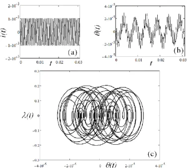
vector is (, ) = (0,0). Fig. 2 provides time plots for the deflection angle and current, and a phase-space plot for (, ). Fig. 3 is the spectral plot (FFT of (a) and (b) in Fig. 1) for the angle (dark line) and current (dotted lines) showing the spectral components that are present in the mechanical and electrical responses. Obviously, the amplitude of the mechanical motion is maximum when Eq. (12) is obeyed (which is not the case shown in Fig. 3). If there is a constant voltage applied to the coil, the galvanometer oscillates with the presence of an AC parallel field. This case (2 in Table 1) is symmetrical to a constant parallel field and alternate current flowing in the coil. To show an example, we make fg = 0 and g = /2. The field frequency is fx = 1500Hz and the applied
voltage is v0 = 1 V. Again the initial condition is (, ) = (0,0)
and the integration time is 1s. Fig. 4 is the spectral distribution of the response movement, showing two main peaks for the resonance and the driving field frequencies. The current in the coil is approximately constant and equal to 1.035 mA.
Fig. 2(a) Current in Amp for 10ms and (b) deflection angle in rad during the first 20ms of time evolution for the galvanometer with magnetic parallel field oscillating at 1600Mhz and driving voltage of 1V at 1400MHz. (c) Phase space plot for the pair (, ) in rad and rad/s for the first 1000 points.
DOI: ISSN: 2318-4531 Fig. 3 Spectral response of the angular oscillation and current showing the
effect of external parallel field fx = 1600Hz and driving voltage fg = 1400Hz.
Dots represent the spectral response for the current for which only the driving potential is important. f0 = 1542 Hz is the mechanical resonance frequency.
Fig. 4 Case 2. Logarithm of the FFT amplitude for with constant current applied to the coil and presence of parallel AC field (fx = 1500 Hz).
C. Cases of transversal field. Inductive galvanometer
According to Eq. (17) and (18), if Bx = 0, there is no driving
term in the system. Therefore, a purely transversal field has no effect on the mechanical motion if (0) = 0.0, that is, there is
no movement and only an AC current in the coil induced by the transverse field frequency is present. However, if the initial condition is such that (0) 0, the resulting motion is
unaffected by the presence of the field. To show a numerical case, we make (, ) = (0.017, 0.0) and use B0y = 0.7 T, fy =
1400 Hz, y = 0 and v0 =0. The spectral response of the current
and mechanical movement is as shown in Fig. 5, which is an example of Case 3. In this case, the response is similar to a damped oscillator with no external excitation.
Fig. 5 Spectral response of Case 3 for an AC transversal field only. The field is unable to affect the mechanical movement. The initial angle is 1 degree. The current response shows two peaks, one for the driving field (1400Hz) and a second due to the induced voltage at the resonant frequency.
The inductive scanner requires the actuation of two fields for the conversion of magnetic into mechanical energy: a parallel DC and a transverse AC fields. The transversal field is responsible for the induction of currents in the coil which are driven by the constant parallel field generating stable motion similar to Case 1. Case 4 is therefore interesting to be studied because it constitutes a new driving mechanism for scanners. Simulation parameters for this case are as follows: B0x = 0.2 T,
fx = 0, x = /2, B0y = 0.2 T, fy = 1600 Hz, y = 0, v0 = 0 and (,
) = (0,0). Results of the integration during 1s and the spectral response are shown in Fig. 6. The movement is stable and restricted to a well-defined region in the (, )-plane. The spectral distribution for the angle and current is very similar to Fig. 5. Two spectral components appear in this case: the resonance and the magnetic field driving frequency. Obviously, for fy f0, the maximum angular deflection is
obtained.
D. Resonance frequency shift
The last case of interest is the actuation of a constant transversal field, a constant current and an alternate parallel field. This is similar to case 2, but the DC transverse field changes the expected resonant behavior of the rotor. If we introduce such driving conditions in Eq. (17) and (18), we can neglect the contribution of BxB’x that appears in the equation
for , since this term averages to zero. Therefore, one obtains an oscillator with a modified resonance frequency:
, 1 2 0 0 J B pvg y (25) which is a new “natural frequency” depending on the intensity of the applied transversal field. The shift in frequency is in fact very small so that we can write:
] [ 4 1 0 Hz R J B nAv f g y . (26)
DOI: ISSN: 2318-4531 Fig. 6 Inductive galvanometer: (,) for the first 1000 integrated points
(above) starting from rest. Spectral distribution of the mechanical response and current (below). There is a prominent peak at the transversal field driving frequency.
Fig. 7 is the spectral mechanical response for vg = 6 V, B0x =
0.2 T, fx = 1600Hz, fy =0Hz, x= 0, y = /2, v = /2 and B0y
in the interval between 0.0 T and 1.2 T. The shift in resonance frequency reaches 0.5Hz when B0y = 1.0 T. At B0y = 1.2 T,
Eq.(26) results in f = 0.62 Hz. The shift in the resonance frequency can be understood as a consequence of the coupling between the coil magnetic moment and the field. This coupling is described in terms of the potential energy:
2 2 1 1 cos
B B B U , (27)Fig. 7 Spectral distribution (f) in the interval from 1535Hz to 1550Hz showing the shift in the mechanical resonance frequency as the transverse magnetic field intensity is increased. For By = 0 T, the resonance peak is at
1542.2Hz. The change in the resonance frequency is 0.62 Hz at By = 1.2T.
the quadratic term acting as a perturbation to the elastic potential, therefore shifting the resonance frequency. The shift signal depends on the product of the applied potential and field signals. Since the effect is proportional to the current, the shift can be increased if the coil resistance becomes small. Since the resistance of common metals (Au, Cr, Al) is strongly influenced by temperature, it is expected that the magnetic perturbation of the mechanical movement will be influenced by temperature changes. The effect described by Eq. (26) is important in the theory of mechanical scanners since it allows the control (through vg and B0y) of the resonance frequency.
Therefore, fine scanner calibration can be electronically achieved, which is important given the expected uncertainties involved in the microfabrication process – minimal variations in the final rotor mass distribution for example.
IV. CONCLUSION
Thus work describes driving mechanisms in galvanometric oscillators, modernly applied in the form of scanners. Data from a silicon microscanner were used to numerically provide examples of the expected behavior for five main cases depending on external driving conditions and feeding potentials. Torsional oscillators can fundamentally work by the actuation of Lorentz force under three magnetic regimes: DC field and AC current, DC current and AC fields or induction of currents by AC fields (short circuited coil). The first and second driving regimes are applications of similar principles used in current measurement devices and motors. The inductive oscillator [Erro! Indicador não definido.] is fed by parallel and transversal field components and the efficiency of the resulting system is severely affected if the amplitude of the parallel field is weak. It was shown that a dipole AC field at 45 degrees in relation to the coil plane can efficiently drive the oscillator. If the transversal field component is constant, the presence of a constant current in
DOI: ISSN: 2318-4531 the coil can induce oscillation in the system at both resonance
and parallel AC field frequency with a small but measurable shift in the resonance frequency. The effect can be enhanced by using small resistance coils.
Therefore, such resonant control could be used to build galvanometric filters. More complex devices [21][22] (for example, double scanners with both X and Y degrees of freedom) could also benefit from the frequency shift induced by magnetic coupling with an external transverse fields. Experimentally, the observation of frequency shift can be implemented by the use of two independent scanners used as laser deflectors of the same light beam. If both have commensurate resonance frequencies, the expected projected light pattern (Lissajous) will exhibit noticeable changes upon any slight variation in one of the mechanical resonance frequencies, assuming that the phase difference between the system pair is well controlled. Other influences could also be studied as, for example, changes in the resonance frequency due to temperature variations [13] of the rotor body since Eq. (26) explicitly depends on coil resistance which is often temperature dependent. Therefore, such resonant control could be used to stabilize [23][24] microscanners in the event of temperature change.
ACKNOWLEDGMENT
The author would like to thank Dr. Luiz Octavio S. Ferreira (DMC/FEM/UNICAMP) for providing micro scanner data and useful discussions.
REFERENCES
[1] Y. Ohira, A. Checkovskiy, T. Yamanoi, T. Endo, H. Fujita, H. Toshiyoshi. “A high-power handling MEMS optical scanner for display applications”, 2008 IEEE/LEOS Internationall Conference on Optical MEMs and Nanophotonics, pp. 70-71, 2008. DOI:10.1109/OMEMS.2008.4607833
[2] C. Mnerie, S. Preitl and V. F. Duma, “Mathematical model of a galvanometer-based scanner: simulations and experiments”, published at the Proc. SPIE 8789, Modeling Aspects in Optical
Metrology IV, 878915, May 13, 2013.
http://dx.doi.org/10.1117/12.2020462
[3] K. Gustafsson, B. Hok. “A silicon light modulator”, J. Phys. E, 21, pp. 420-457, 1988.http://iopscience.iop.org/0022-3735/21/7/011/ [4] K. E. Petersen. “Silicon torsional scanning mirror”, IBM J. Res. Develop. 24, pp. 631-637, 1980. DOI: 10.1147/rd.245.0631
[5] N. Asada, M. Takeuchia, V. Vaganov, N. Belov, S. in't Hout and I. Sluchak, “Silicon micro-optical scanner”. Sensors and Actuators A: Physical, 83, pp. 284-290, 2000. http://dx.doi.org/10.1016/S0924-4247(00)00352-6
[6] M. Bayer, “Retinal Scanning Display - a Novel HMD Approach to Army Aviation”, Proc. SPIE on Head and Helmet-Mounted Displays VII, Vol. 4711, Orlando, Florida, April 2002. http://dx.doi.org/10.1117/12.478873
[7] L. O. S. Ferreira, S. Moelecke. “A silicon micromechanical galvanometric scanner”. Sensors and Actuators, 73, pp. 252-260, 1999.
[8] J. Montagu, Handbook of Optical and Laser Scanning, Chapter 8, Ed. By C. F. Marshall, CRC Press, 2004. http://dx.doi.org/10.1016/S0924-4247(98)00288-X
[9] G. Marshall, Ed., Optical Scanning, Marcel Dekker, New York, 1991.
[10] H. Schenk, P. Durr, D. Kunze, H. Lakner, H. Kuck, “An Electrostatically Excited 2D-Micro-Scanning-Mirror with an In-Plane Configuration of the Driving Electrodes”, IEEE MEMS Proceedings, Vol. 13, p. 473-478, 2000.
[11] M. Fischer, H. Graef, W. von Munch. “Electrostatically deflectable polysilicon torsional mirrors”. Sensor and Actuators A, 44, pp. 83-89, 1994. http://dx.doi.org/10.1016/0924-4247(94)00785-3 [12] S. Schweizer, P.Cousseau, G. Lammel, S. Calmes, Ph. Renaud, “Two-dimensional thermally actuated optical microprojector”, Sensors and Actuators, Vol. 85, p. 424-429, 2000.
[13] W. Riethmuller, W. Benecke. “Thermally excited silicion microacturators”. IEEE Trans. Electron. Dev., 35, pp. 758-765, 1998. DOI: 10.1109/16.2528
[14] J. M. Zara and S. W. Smith. “Optical Scanner Using a MEMS Actuator”. Sensors and Actuators A: Physical, 102, pp. 176-184, 2002. http://dx.doi.org/10.1016/S0924-4247(02)00302-3
[15] V. F. Duma and A. G. Podoleanu, “Theoretical approach on a galvanometric scanner with an enhanced duty cycle”, presented at the 1st Canterbury Workshop on Optical Coherence Tomography and Adaptive Optics, Edited by Podoleanu, Adrian. Proceedings of the SPIE, Volume 7139, article id. 71390D, pp. 8 pp., 2008. http://dx.doi.org/10.1117/12.810340
[16] V. F. Duma, A. Gh. Podoleanu, M. Nicolov, “Modeling a galvoscanner with an optimized scanning function”, presented at the 10th IFToMM Intl. Symposium on Science of Mechanisms and Machines, Brasov (Romania), Ed. Springer, pp. 539-548, 2009. DOI: 10.1007/978-90-481-3522-6_45.
[17] V. F. Duma, “Mathematical Functions of a 2-D Scanner with Oscillating Elements”, Modeling, Simulation and Control of Nonlinear Engineering Dynamical Systems, pp 243-253, 2009. Doi: 10.1007/978-1-4020-8778-3_22
[18] H. Urey, “Torsional MEMS scanner design for high-resolution display systems”, published at Optical Scanning II, Proc. SPIE vol. 4773, p. 27-37, 2002.http://dx.doi.org/10.1117/12.469198
[19] L. C. M. Oliveira, P. R. Barbaroto, L. O. S. Ferreira and I. Doi, “A novel Si micromachined moving-coil induction actuated mm-sized resonant scanner”, Journal of Micromechanics and Microengineering, 16, 165, 2006. doi:10.1088/0960-1317/16/1/022 [20] W. H. Press, S. A. Teukolsky, W. T. Vetterling, B. P. Flannery. Numerical Recipes in C, the art of scientific computing, 2nd Ed., p. 710, 2000.
[21] K M Ahmid, L O S Ferreira, R Pavanello. “Investigation of the dynamic behavior of a double paddle scanner”. ABCM Symposium Series in Mecatronics, 1, 707, 2004.
[22] J. W. Judy, R. S. Muller. “Magnetic microactuation of torsional polysilicon structures”. Sensors and Actuators A, 53, pp. 392-297, 1996. http://dx.doi.org/10.1016/0924-4247(96)01138-7
[23] J.Kim, Y. Kawai, N. Inomata, T. Ono. “Parametrically driven resonant micro-mirror scanner with tunable springs”, 2013 IEEE 26th International Conference on Micro Electro Mechanical Systems
(MEMS), pp. 580-583, (2013). DOI:
10.1109/MEMSYS.2013.6474308
[24] Torsion oscillator stabilization by M. C. Klement, (2004, Sept 21), Patent US 6,794,794 B2.