Analyses of composite structures behaviour with embedded Bragg
grating sensors
C.A.Ramos
1,a, J.L. Esteves
2,c, R.A. Silva
1,b, A.T.Marques
2,d1
Departamento de Física, Instituto Superior de Engenharia do Porto, ISEP. Rua Dr. António Bernardino de Almeida 431, 4200-072 Porto, Portugal.
a
email: [email protected]
b
email: [email protected]
2
Departamento de Mecânica, Faculdade de Engenharia da Universidade do Porto, INEGI. Rua Dr. Robert Frias s/n, 4200-465 Porto, Portugal.
c
email: [email protected]
d
email: [email protected]
Keywords: Health monitoring, Composite Structures, Fibre Bragg Grating
Abstract: Structural health monitoring of composite structures may be accomplished by measuring
strains with embedded optical fibre sensors. In this paper, we present the performance of Bragg grating sensors, which are imbedded into a carbon composite laminate and them bonded to the structure in analyse. The paper will briefly discuss the results and compare them with a free fibre Bragg grating bonded in the surface of the carbon composite laminate, with existing electrical strain gauge installation and with a numerical analysis by the finite element method.
Introduction
Structural health monitoring of composite structures may be accomplished by measuring strains with embedded optical fibre sensors. In the composite smart structures development, the fibre optic Bragg grating (FBG) sensors offer many benefits compared to their electric counterparts[1,2]. Most important is their immunity to electromagnetic interference, which enables applications under difficult environmental conditions [3,4]. FBG sensors are small, lightweight and can easily be integrated into structures, a property that is especially attractive for composite materials where fibre optics can be used to implement smart structures. It has been demonstrated that the optical fibre may be placed inside a composite without affecting the structural integrity of the composite [5].
Employing Bragg grating sensors is perhaps the best solution since these sensors are intrinsic, i.e. they are no more disturbing to the host structure than a regular optical fibre. In addition, FBG sensors have a high potential for low cost, but there are still a number of open questions to be answered before applying FBG’s in real-world applications. For example, the method of attaching the sensor to the structure to be monitored remains a major challenge.
Two mounting methods do exist that offer potential for future employment. Bonding the fibre onto the surface of the structure is an excellent method for short-term applications if the operating environment is not too harsh. Bragg grating sensors can also be embedded in fibre reinforced composites [6], but the relation of sensor signal to strain level inside the material is extremely complex.
To obtain good optical strain measurements over a wide strain range, the response of the sensors must be understood and the optical fibre must be mechanical sound. Further, they must survive the cure cycle of the composite and be able to function in the embedded state. However, the mechanical performance of the embedded sensors must at least match that of the host structure to be useful. There is therefore a need to establish that such sensors can perform in their internal
environment. Thus, the viability of integrating Bragg grating sensors into the composite structures is of major interest.
Experimental Procedure
Bragg Grating Sensor. A FBG is a periodic modulation of the refractive index of the core of a
single mode optical fibre, written by exposure to UV light in the region around 248 nm [9]. This fabrication process is based on the photosensitive mechanism, which is observed in Ge-doped optical fibres [8]. If broadband light is travelling through an optical fibre containing such a periodic structure, its diffractive properties promote that only a very narrow wavelength band is reflected back. The centre wavelength of this band can be represented by the well known the Bragg condition:
Λ =
λB 2neff (1)
Where λB is the centre wavelength, neff is the effective index of the guided mode and Λ is the
period of the index modulation. The FBG resonance wavelength will vary accordingly with strain changes experienced by the fibre. The wavelength shift, induced by a longitudinal strain variation
∆λB is given by,
(
−)
∆ε λ = ε ∆ ε ∂ ∂ + ε ∂ Λ ∂ Λ λ = λ ∆ B B B1 pe n n 1 1 (2)Where pe is the photoelastic coefficient of the fibre, For a silica fibre, the wavelength-strain is
typically around 1.15 pmµε-1, for a Bragg wavelength centred at 1555 nm [7]. In the present study,
all the experiments were realized at room temperature (23±2 ºC and 50±5 % RH).
Composite laminate sensor. The composite laminates were fabricated using carbon fibre
reinforced plastic (CFRP) with epoxy resin pre-impregnated (SEAL CC206, twill 2/2). The prepeg was cut, with the dimensions 100×20 mm2, and laid up by hand, placing the optical fibres in the mid-plane of the laminate along 100 mm direction. After lay-up, the laminate was vacuum-bagged and placed in an autoclave, where it was slowly heated to 130 ºC under internal vacuum and 0.1 MPa of external pressure. After holding for 1 hour at this condition, the laminate was slowly cooled in the autoclave. The laminate was trimmed along side edges to its final dimensions, and with a thick of 0.4 mm.
The optical fibre used in this composite laminate, was a single mode fibre with an acrylate
coating, SMF 28 of Corning. The fibre diameter is 250 µm with the coating, and 125 µm excluding
the coating thickness, and the attenuation for 1550 nm is < 0.22 dB/km. The Bragg grating has a length of 10 mm.
For a better understanding of the comportment of the FBG sensors when embedded, we created a experimental set-up formed by the carbon composite laminate sensor with the FBG sensor embedded, bonded in a glass fibre reinforced plastic (GFRP – cross plie laminate) plate with the
dimensions 300×50×3.45 mm3. The set-up was also monitorized with six electrical stain gages
(SG), and a free fibre Bragg grating bonded on the surface of the carbon composite sensor. The characteristics of the set-up materials used are summarised in the Table 1.
Table 1 – Mechanical properties of set-up materials.
CFRP GFRP Adhesive Araldite
AW106 + HV953U
E (Young modulus) [GPa] 70.687 19.290 1.200
ν (Poisson coef.) 0.025 0.130 0.330
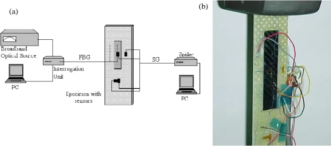
The set-up used for health monitoring of the composite structure behaviour, can be observed in Fig.1, and in Fig. 2, the placement of the FBG and SG sensors.
Fig. 1 – Set-up used in the measurements, for FBG and SG sensors (a), and the specimen mounted in the machine test (b).
Fig. 2 – Localisation of the FBG and SG sensors.
Results
A tensile test were performed to investigate the influence of an applied stress on the shape on the FBG spectrum, and compared with SG, in the same relatively positions. Excellent linearity is noted in the spectrum over the entire testing regime. Fig. 3 shows the spectral response of the sensors, when the specimen is under tensile loading. Fig. 4 shows a linearity plot when the specimen is tested.
(a) (b)
0 50 100 150 200 250 0 50 100 150 200 250 300 350 400 450 500 S tr ai n ( µε ) Time (s)
Fig. 3 – Behaviour of FBG and SG sensors
200 300 400 500 200 300 400 500 F B G ( µε ) SG (µε) R2 =0,9998 Fig. 4 - Linearity plot for the sensors
Fig. 5 shows the field of the tension stress, across GFRP plate and CFRP plate sensor. In Table 2, we present a comparison with the experimental measurements made by the FBG and SG sensors and the numerical calculations.
Table 2 – Results obtained and calculated SG [µε] FBG Embedded [µε] FBG Bonded [µε] FEM [µε] D 614 - - 543 E -78 - - - F 513 - - - I 588 - - 658 G 490 - - 626 H 454 - 452 401 CFRP - 547 - 410
Fig. 5 – Tension Stress Field across the sensor plate and GFRP structure
From Table 2, we can observe that the values read for the SG, FBG sensors and calculated numerically are of the same order of magnitude. The readings realized for SG and FBG sensors in the surface of sensor plate CFRP are identical and slightly superior to the gotten ones for the numerical calculations. The superior value for the FBG embedded sensor, possibly results from the fact of the sensor is under tension as resulted of the composite cure cycle, but it will be necessary for this type of sensors to effect a optimisation of the production process that implies a reduction of the internal tensions in the zone around the sensor.
Conclusion
It can be observed that plate sensor CFRP, suffers an inferior deformation to the one from structure GFRP in analysis, possibility due to bigger stiffness of the CFRP plate, and to the very low stiffness of the adhesive used in the bond of the sensor plate. This last one may act as a filter not transmitting the totality of the deformation at the surface of structure GFRP, for the sensor plate.
The present paper summarizes some of the activities that have been carried out at this unit for health monitoring in composite materials, in the development of a fibre optic strain measurement system.
A non-uniform strain distribution generated by compressive strains exerted by adjacent fibres is thought to have contributed to the shape of the spectrum of the FBG embedded in high performance composites and laminates.
A lower cure temperature is more desirable, to decrease the residual strain-stress, since the residual strain-stress is induced by the thermal expansion mismatch between the reinforcing fibre - and matrix shrinkage during curing and the cool down period. However, the low cure temperature desirable for reducing residual stresses requires a longer curing time, but a long curing time is not economical, consequently, a compromise must be reached as regards these two parameters.
The tensile tests have demonstrated that specimen exhibiting a good linearity plot between the different kinds of sensors used in this experiment. Its possible to concluded that the FBG sensor some times exhibiting anomalous spectrum comportments, witch may lead to strain anomalies.
It has necessity to continue the works of the optical fibre embeddement to use in the production of the sensory plate with a composite of inferior stiffness to the one of the structure to be monitorized.
Acknowledgements
The authors would like to thank the Foundation for Science and Technology, and the program PRODEP III – Medida 5 – Acção 5.3, for the support. To INEGI, composite materials unit, and to INESC, optoelectronic unit, for their facilities.
References
[1] E. Udd: Fibre Optic Smart Structure Technology, In Fibre Optic Smart Structures, John Wiley & Sons, Inc., ISBN 0-471-55448-0 (1995), p. 5-21.
[2] M. Le Blanc, R.M. Measures: Fibre Optic Damage Assessment, In Fibre Optic Smart Structures, John Wiley & Sons, Inc., ISBN 0-471-55448-0 (1995), p. 518-613.
[3] D.A. Krohn: Fibre Optic Sensors, Fundamentals and Applications, Instrument Society of America, third edition, ISBN 1-55617-714-3, (2000).
[4] G. Zhou, L.M. Sim: Damage detection and assessment in fibre-reinforced composite structures with embedded fibre optic sensors-review, Smart Mat. Structures, Vol. 11 (2002), p. 925-939. [5] R. Measures: Fiber Optic Strain Sensing, Smart Structures, E. Udd Ed., ISBN 0-471-55448-0
(1995), p. 171-247.
[6] A. Skontorp: Effect of Embedded Optical Fibers on the Structural Integrity of Composites (Proc.
12th ICCM Conf., Paris, France 1999).
[7] K.O. Hill, B. Malo, F. Bilodeau, D.C. Johnson, and J. Albert: Bragg gratings fabricated in monomode photosensitive optical fiber by UV exposure through a phase mask, Appl. Phys. Lett., Vol. 62 (1993) p. 1035-1037.
[8] K.O. Hill, B. Malo, F. Bilodeau, D.C. Johnson: Photosensitivity in optical fibers, Annu. Rev. Mater. Sci. vol. 23 (1993) p. 125-157.
[9] W.W. Morey, G. Meltz, W.H. Glenn: Fibre optic bragg grating sensors, (Fiber Optic and Laser Sensors VII, in Proc. SPIE 1169, Boston, USA, pp. 98-107, 1989).