Leiria, October of 2018
Dissertation
Master in Civil Engineering – Building Construction
Modeling and prototyping of composite
products
Leiria, October of 2018
Dissertation
Master in Civil Engineering – Building Construction
Modeling and prototyping of composite
products
Ziabkin Yahor
Dissertation developed under the supervision of professor Paulo Alexandre Lopes Fernandes, adjunct professor at Departament of Civil engineering of the Polytechnic Institute of Leiria and co-supervision of professor Dmitry Shabanov, professor at the Politsk State University of Civil Engineering.
RESUMO
Atualmente, a tecnologia de avaliação do ciclo de vida de produtos industriais passa pela fase de mudança do estágio de existência no mercado - de inovações à aplicação industrial. Em alguns anos atrás praticamente não havia exemplos de projetos usando modelos de informação no mercado amplo, hoje a situação está mudando, inclusive porque a modelagem de informação foi percebida em nível estadual. A necessidade de produzir produtos inexistentes dentro do país estimula investimentos em nova produção e reequipamento de instalações existentes, e tais projetos devem ser implementados da maneira mais rápida e eficiente possível. A principal tarefa é acelerar a implementação do projeto de investimento e construção, reduzir custos e aumentar a rentabilidade da construção.
O tema da tese corresponde ao programa de ramo da República da Bielorrússia sobre o desenvolvimento e implementação de tecnologias da informação para automação integrada de design e avaliação do ciclo de vida de edifícios e estruturas. O trabalho de mestrado é parte integrante da questão do orçamento do Estado n º 2916 do departamento de produção de construção "Desenvolvimento e pesquisa de materiais inovadores de economia de energia e recursos, tecnologias que utilizam matérias-primas da região de Polotsk".
Os resultados do trabalho representam a possibilidade de modelagem e introdução de novos tipos de perfis periódicos, criação de tecnologia de impressão 3D para estruturas reforçadas com reforço compósito de perfil periódico, criação de grampos reutilizáveis de uso reutilizável para teste de armadura composta de diversos perfis periódicos .
Palavras-chave: modelagem, compósito, prototipagem, reforço, perfil periódico, impressão3D.
ABSTRACT
Nowadays, the technology of life cycle assessment of industrial products passes through the stage of changing the stage of existence in the market - from innovations to industrial application. In a couple of years ago there were practically no examples of projects using information models on the broad market, today the situation is changing, including because information modeling was noticed at the state level. The need to produce non-existent products inside the country stimulates investments in new production and re-equipment of existing facilities, and such projects must be implemented as quickly and efficiently as possible. The main task is to accelerate the implementation of the investment and construction project, reduce costs and increase the profitability of construction.
The theme of the thesis corresponds to the branch program of the Republic of Belarus on the development and implementation of information technologies for integrated automation of design and life cycle assessment of buildings and structures. Master's work is an integral part of the state budget issue No. 2916 of the department of construction production "Development and research of innovative energy- and resource-saving materials, technologies using raw materials of the Polotsk region".
The results of the work represent the possibility of modeling and introducing new types of periodic profiles, creation of 3D-printing technology for structures reinforced with composite reinforcement of periodic profile, creation of reusable end clamps of reusable use for testing composite reinforcement of various periodic profiles.
Keywords: modeling, composite, prototyping, reinforcement, periodic profile, 3D-printing.
List of figures
Figure 2.1. - Graph of the linear shrinkage of polymer from temperatures. .... 7
Figure 3.1. - Educational testing machine NTC-13.04.20 "Tearing machine 20kN". ……… 9
Figure 3.2. - Opti microscope "Altami MET 5C". ……… 10
Figure 3.3. - The graph, built by NTC-13.04.20. As a result test of a GRP tensile test. ……… 10
Figure 3.4. - Graph of the stress-strain state of a GRP specimen. ………… 11
Figure 3.5. - Fracture of a glass fiber plastic sample. ……… 11
Figure 3.6. - Test plan for bending specimens. ……… 12
Figure 3.7. - Types of tested fiberglass profiles fittings. ……… 13
Figure 3.11. - Graph of evaluation of the linear model. ……… 18
Figure 3.13. - Limit value of deformations of all components of the glass-reinforced plastic reinforcement with periodic profile, with tension. . .20 Figure 3.14. - Transverse and longitudinal form of fibers fiberglass reinforcement with periodic profile, after stretching. ……….21
Figure 4.1. - Profile of composite reinforcement of elliptical type. ……… 24
Figure 4.2. - Profile of composite reinforcement of rectangular shape. …… 24
Figure 4.3. - Profile of composite reinforcement in zigzag shape. …………24
Figure 4.4. - Additional roving protection by resin treatment. ……… 24
Figure 4.5. - 3D model of the selected composite profile fittings in the program complex T-FLEX CAD. ……… 25
Figure 4.6. - Deformations and tensile stresses experienced by a model of a given profile. ……… 26
Figure 5.1. - Export assembly to STL-format for 3D-printing. ……… 29 Figure 5.2. - The Mojo 3D printer software window. ……… 29 Figure 5.3. - Prototype of the rod printed on the 3D printer Mojo. ……… 29 Figure 5.5. - Devices for fixing the ends of composite fittings (Genina E., Ph.D.) ……… 31 Figure 5.6. - Device for fastening the ends of composite reinforcement
(Shabanov D., Ph.D.). ……… 31 Figure 5.7. - Spatial image of the attachment device ends of composite
fittings (Shabanov D., Ph.D.). ……… 31 Figure 5.8. - Model of terminal clamps created in software complex
ANSYS SpaceClaim. ……… 32 Figure 5.9. - Stress-strain state of the end clamps created in the software package T-FLEX CAD. ……… 33 Figure 5.10. - The parameter m in equation (5) with respect to base side. ...34 Figure 5.11. - Prototype terminal clamp for testing and obtaining
prestressed composite reinforcement with periodic profile. ………35 Figure 5.12. - Prototype of the end clamp in the tensile machine. …………35 Figure 5.13. - Fencing structure model. ……… 36 Figure 5.14. - Construction of a 3D building printer. ………37 Figure 5.15. - Printing unit for composite reinforcement with periodic
List of tables
Table 3.8 - Results of testing 3 kinds of fiberglass reinforcement profiles for bending. ……… 13 Table 3.9 - Comparison of destruction of three different types of fiberglass reinforcement with periodic profile. ……… 15 Table 3.10 - Dependence of absolute strain on load for composite
reinforcement with periodic profile. ……… 17 Table 3.12 - Physical and mechanical characteristics of fiberglass
reinforcement with periodic profile 0,30σ with a cross-sectional area of 8 mm. ……… 19 Table 5.4 - Strength characteristics of the plastic used to create a prototype composite reinforcement periodic profile. ……… 30
Table of Contents
RESUMO……….………… VI ABSTRACT……….……… VI LIST OF FIGURES………. VI LIST OF TABLES………... VI TABLE OF CONTENTS ……… VI CHAPTER 1. INTRODUCTION……… 1 1.1 General ……….……….. 1 1.2 Objectives……….………... 2 1.2 Srtucture……….………. 3CHAPTER 2. ANALYSIS OF THE USE OF THE COMPOSITE REINFORCEMENT WITH PERIODICAL PROFILE IN CONSTRUCTION……… 4
2.1 General concepts of the composite reinforcement with periodic profile ……….……… 4
2.2 Investigation of the operational properties of the composite reinforcement with periodic profile……….……… 6
CONCLUSIONS BY CHAPTER……… 8
CHAPTER 3. ANALYSIS OF STRESSED-DEFORMED CHARACTERISTICS OF THE COMPOSITE REINFORCEMENT WITH PERIODIC PROFILE……… 9
3.1 Research methods………..……… 9
3.1.1 Testing of the composite reinforcement with periodic profile for tension ……….……… 10
3.2 Testing of the composite reinforcement with periodic profile for bending ……… 12
3.3 Detection of the possibility of prestressing of composite reinforcement with periodic profile……… 16
CONCLUSIONS BY CHAPTER ……… 22
CHAPTER 4. COMPUTER MODELING OF COMPOSITE REINFORCEMENT WITH PERIODIC PROFILE ……… 23
4.1 Creation of a unique periodic profile of composite reinforcement ……… 23 4.2 Testing of the modeled composite reinforcement of the profile
for tension ……… 25
CONCLUSIONS BY CHAPTER ……… 27
CHAPTER 5. PROTOTYPING WITH THE APPLICATION OF 3-D PRINTING, AS A NEW STAGE IN THE BUILDING
INDUSTRY……… 28
5.1 Creation of a prototype of a composite reinforcement with
periodic profile ……….. 28
5.2 Modeling of the device for multiple tests of composite
reinforcement of a periodic profile………….……… 5.3 Building 3D printer with the ability to print composite
reinforcement with periodic profile………
30
36
CONCLUSIONS BY CHAPTER ……… 38
CONCLUSION……… 39 REFERENCES ……… 40
1. INTRODUCTION
1.1 General
Nowadays, the technology of life cycle assessment of industrial products passes through the stage of changing the stage of existence in the market - from innovations to industrial application. In a couple of years ago there were practically no examples of projects using information models on the broad market, today the situation is changing, including because information modeling was noticed at the state level. The need to produce non-existent products inside the country stimulates investments in new production and re-equipment of existing facilities, and such projects must be implemented as quickly and efficiently as possible. The main task is to accelerate the implementation of the investment and construction project, reduce costs and increase the profitability of construction [1].
This work was carried out in accordance with the sectoral program of the Republic of Belarus on the development and implementation of information technologies for integrated automation of design and life cycle of buildings and structures [2].
Communication of the construction industry with computer technology is formed for years and nowadays the benefits from it are obvious to specialists of different directions. Mainly, virtual modeling tools are used, which allow the development of various projects with high accuracy [3]. Therefore, it is necessary to link science and real construction with the help of system management decisions, fresh approaches to the introduction of technologies and scientific developments [4].
The use of the method of modeling has become a characteristic feature of science. It is the application of information models with accompanying construction processes that can significantly affect the rate at which objects are put into operation. Verification of the project for all possible conflicts and errors - geometric, technological, spatio-temporal, comparison of design schedules, procurement and construction, efficient work planning, issuing tasks, monitoring construction processes, checking the quality of work, etc. - these are the tasks whose effective solution today is virtually impossible without the use of information models [5].
Often, numerical simulation eliminate the need to conduct full-scale experiments. In the same place, where imitation is not possible without confirmation on physical samples, numerical simulation allows to reduce significantly the number of experiments by selecting the optimal design parameters, thereby reducing the costs for approbation of results or certification of the product. Often, the results of virtual tests give a wide picture of the processes that are happening than a full-scale
experiment, providing more opportunities for optimizing and improving performance, while saving considerable time and resources.
In addition, the application of numerical and experimental research methods is practiced, when the results of full-scale tests are supplemented with results of simulation modeling, which are unattainable in the field experiment.
As it was noted, construction is the only completely non-automated industry sector. After all, it is known that human participation is needed at different stages and this leads to low speed, labor costs, constant overdelivery of the budget and corruption. And also, construction as the first place in work accidents, making this activity as one of the more dangerous. It is estimated that the digitalization in the construction will radically change this situation, reducing production cost by 20-25%, material consumption by 25-30% and labor cost by 45-55% [6].
The use of 3D printers in construction should give many advantages. The main of them is the high speed of construction of cement concrete foundations, automobile and airfield coatings and full robotization of the coating reinforcement process.
For example, with the use of new technologies for 3D printing of three-dimensional structures, called 3D Cocooner, the robot, in accordance with the task, produces structures of fiberglass thread whose surface has a small roughness. Once the viscous filaments leave the spinneret to form the fibers, they are laminated with a polymer fixed by UV light. Then they create complex structures. Unlike other 3D printing processes, 3D Cocooner designs are not printed as a result of layer-by-layer synthesis, but are freely created in three-dimensional space, which makes it possible to obtain the design closest to the actual samples. The product is printed with the help of finished glass-fiber [7].
The paper also presents the technology developed by the scientific team of the Polotsk State University, which can be used for 3D printing of products reinforced with continuous composite threads. Printing of the product is due to the composite reinforcement of the periodic profile, obtained previously in a 3D printer.
1.2 Objectives
The purpose of the thesis is to identify the possibility of modeling the deformations of a composite reinforcement of a periodic profile. Improvement of the technology of contour construction by printing fiberglass reinforcement of the periodic profile as a reinforcing element of the enclosing structures. Creating prototypes of simulated profiles. Creation of collapsible end clamps for testing of composite reinforcement of periodic profiles.
To achieve this goal, the following tasks have been accomplished:
composite reinforcement of a periodic profile is identified;
2. A prototype of the simulated periodic profile of composite reinforcement is obtained;
3. A 3D-printer project has been developed that produces structural elements reinforced with a periodic-profile fiberglass reinforcement;
4. Demountable end clamps for testing the composite reinforcement of periodic profiles are created.
The object of investigation is composite reinforcement of various periodic profiles. 3D modeling and printing with the subsequent receipt of prototypes.
The subject of the research is macro- and microstructure of composite reinforcement, physical and mechanical characteristics of composite reinforcement of various periodic profiles.
1.3 Structure
Present research work consists of 4 chapters. Chapter 1 contains the introduction, objectives and structure of the work done.
Chapter 2 contains general concepts of the composite reinforcement with periodic profile. Also this chapter contains, Investigation of the operational properties of the composite reinforcement with periodic profile.
Chapter 3 describes the main materials, techniques and equipment used in research work. This chapter shows a part of the experimental work, testing for tension and bending and also detection of the possibility of prestressing of composite reinforcement.
Chapter 4. In this part presented results of creation of a unique periodic profile of composite reinforcement and also results of testing of the modeled composite reinforcement for tension.
Chapter 5 outlines materials and results about creation of prototype of composite reinforcement with periodic profile.
2. ANALYSIS OF USING COMPOSITE
REINFORCEMENT WITH PEDIODICAL PROFILE IN
CONSTRUCTION
2.1 General ideas about the composite
reinforcement with periodic profile
As construction practice has shown, despite numerous advantages, reinforced concrete has a number of shortcomings, as a result of which research is currently under way to develop a new material that will eliminate the disadvantages of reinforcing steel and will have all its advantages. An alternative to steel reinforcement, is the composite reinforcement [8].
Recently, scientific research has been carried out to implement the principle of facilitating and simultaneously enhancing the load-bearing capacity of structures by replacing steel in reinforced concrete structures with non-metallic reinforcement. Replacement of steel reinforcement composite can increase the durability of structures operated under the influence of corrosive environments, in the presence of stray currents, and expand the scope of concrete antimagnetic and dielectric reinforced structures [9].
Modern ideas about the use of nonmetallic reinforcement have received a wider resonance, i.e. application in the design in conjunction with the metal. However, their physico-mechanical characteristics are much better. For composites based on polyester resins, a number of general properties relating to their chemical resistance are determined based on the chemical structure of the resins being esters. Polyester resins are resistant to the action of many inorganic and organic acids (with the exception of strong oxidizing acids), oils and many solvents. They partially swell under the influence of such strong solvents as chlorinated carbohydrates [10].
Considering the fact that when reinforcing concrete structures, the effective use of composite reinforcement is possible only when the prestressing of the rods is performed, the periodic profile of the reinforcement ensuring the joint work of reinforcing bars and concrete takes on special importance [11].
It should also be remembered that the joint operation of reinforcement and concrete, as a criterion for the reliability of structures, is possible only if there is a reliable cohesion between them. The greatest influence on adhesion has a periodic profile, applied to the surface of the reinforcement in the process of its manufacture. In this connection, the improvement of the shape and parameters of the periodic profile of reinforcement is an important task, aimed ultimately to improve the
performance characteristics of structures for various purposes and increase their reliability. Such bond factors as frictional and gluing forces depend on the area of contact of the reinforcement with concrete. Therefore, the ratio of the height of the transverse protrusions to their step h / t is taken as the basis for estimating the effect of the parameters of the periodic profile of the composite reinforcement on the adhesion to concrete. To study the influence of the geometric dimensions and the construction of the reinforcement profile on its adhesion to concrete, tests are carried out for drawing reinforcing bars from concrete cubes or prisms, according to the power test scheme they are "pulling the reinforcement from concrete".
Composite rod in the form of "rope" has at the ends of anchor thickenings in the form of monolithic "nodes". This factor provides 70-75% of the total shear resistance. The remaining 30-25% fall on the bonding of reinforcement with concrete and friction along the surface of their contact. Based on this, an analysis of various cable rope designs was carried out, and the following relationship was obtained through the similarity for estimating the friction of a composite rod with concrete:
3 б F P S q F Fl F , (1),
where P is the resistance to shear of the rod in concrete per unit length; F̅ - is the total cross-sectional area of the rovings forming the rod; l - the length of the rod twist step; F3 - the meshing area for the pitch section of the string; S̅ - is the perimeter of the cross-section of the rod along the line of contact with concrete; - coefficient of completeness of the meshing area; б - normal stresses between the core and concrete acting on the meshing areas; - tangential stresses on the surface of the rod contact with concrete.
In the total adhesion value, the main factor (linkage) is characterized by the first term of the formula. Below the engagement area is meant the difference between the area of the circle circumscribed around the core and the cross-sectional area of the rod, increased by m times (m is the number of elements of the outer layer, for twisted reinforcement m = 2) [12].
The characteristic of the clutch is determined for various reinforcement ropes. The analysis revealed that rods, twisted from two initial elements (double-strand rope), possess the best coupling. They are also the most simple in manufacture, powerful enough and possessing high adhesion to concrete. The clutch of double-strand ropes with concrete is approximately twice as high as the original double-strands. This means that parameters such as the anchoring zone and the termination zone in the concrete remain the same for the rope in absolute value (and in some cases are smaller) as for the original strands [13].
which they immediately turn into rubbish. Another and not less important disadvantage is the loss of stability of the material to combustion over time, during drying. It should also be noted the need for a moisture barrier layer [18].
2.2 Investigation of the operational properties of
the composite reinforcement with periodic profile
Investigations of deformation characteristics of polymeric materials are inextricably linked with the tasks of comparative analysis of their properties, with studies of the relationship of properties with structure, with purposeful technological adjustment of properties, as well as with the forecasting of short-term and long-term mechanical effects. The studied deformation properties of polymeric materials are influenced by temperature effects, as well as the levels and duration of mechanical influences. For comparative analysis and forecasting of these properties, it is necessary to develop a mathematical model based on a physically based analytical description of these influences. The greatest attention deserves solutions when there is a physical justification for the chosen equations in combination with a minimum of the number of parameters used. It should be noted that the study of the mechanical properties of polymer products, manifested in operating conditions, is much more difficult than measuring only discontinuous characteristics, which are far from an objective evaluation of the properties of the material. Of special value is the solution of such a problem for polymers, when, in addition to comparing the mechanical properties of materials, we also have to make calculations for the conditions of operation of the products.
Defining characteristics when creating products from composite materials are [11,14]:
elastic modulus for tension and shear of fibers should be greater than the binder Eu> Em; Gf> Gb
- the strength of the fibers should be greater than the binder sf * *> sb *; the elongation at fiber rupture should be somewhat less than the binder eb * <em *;
Poisson's coefficients for roving and the matrix should be sufficiently close to μp ≥ μm, so that when the composite is deformed at the interface of the fiber-matrix there are no stresses that tear them apart and thereby reduce adhesion;
The interaction of fibers with the matrix should ensure a high realization of the mechanical properties of fibers in the reinforced material and its monolithicity. This is realized due to the good wettability of the fibers with the matrix (binder), as well as high adhesion between the fiber and the matrix. An important role is played by the relaxation of internal stresses in the elementary volume of the fiber matrix.
Reinforcing fibrous material - namely roving, containing a specified amount of fibrous filler, allows you to regulate the diameter of the resulting rods. Resins are usually used as a binder (NorpolDion 6694, Atlas-580, EVS-9133). they have better resistance to acids, alkalis and especially to chlorine media. Vinylester resins are cured as well as polyester resins, similar in physical and mechanical properties to epoxy resins, have better impregnation and wetting properties of reinforcing filler materials and polymerization, are easier to process than epoxy resins, and are highly water resistant [15].
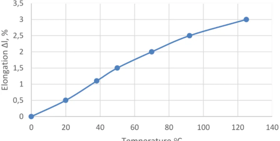
The curing of the epoxy binders is accompanied by the formation of a spatially crosslinked structure and shrinkage of the polymer, which reaches about 3.5%, as seen in Figure 2.1. Temperature shrinkage leads to the formation of defects in the structure of the material [16,17].
Figure 2.1. - Graph of the linear shrinkage of polymer from temperatures
At present, based on experimental data and developed ideas on the structure of composite materials, a number of relationships between their basic properties and the most significant factors have been established, which are used in technological calculations and tests to find approximate estimates of the stress-strain state [18, 19].
However, for several decades scientists of many countries have been trying to create their ideal model of clamps for obtaining and studying the stress-strain state of composite reinforcement. A lot of work has been done, but the best solution to this problem has not been found. The creators of the test fixtures for composite reinforcement tried to influence it by the large contact area of the clamping elements, not excluding the occurrence of stress concentrators [20].
Experience has shown that when steel wedges are used in seizures, the destruction of the samples takes place mainly in the places where the voltage concentrators occur. Based on earlier studies and their analysis [21, 22], it can be
0 0,5 1 1,5 2 2,5 3 3,5 0 20 40 60 80 100 120 140 Elon gat ion Δl, % Temperature оС
noted that in the case of creating new types of profiles of composite fittings, as well as terminal clamps reusable for its testing, these developments will be in demand in the construction market in different parts of the world.
Analysis of the problem with consideration of the physical and mechanical characteristics of composite reinforcement of various periodic profiles suggests that the creation and application of new types of periodic profiles of composite reinforcement as the main reinforcing materials can be an innovative and promising solution. Especially actual direction in the solution of the task will be to obtain prestressing of composite reinforcement, with the help of reusable end clamps of reusable use.
Conclusion by chapter
1. Partial replacement of steel reinforcement composite can increase the operational properties of products, reduce their metal content and weight of structures.
2. When reinforcing concrete structures, the effective use of composite reinforcement is possible due to the same coefficient of linear expansion, and also the periodic profile of the reinforcement, ensuring the joint operation of reinforcing bars and concrete, acquires special importance.
3. Simulation of the shape and parameters of the periodic profile of reinforcement is an important task, aimed ultimately to improve the performance characteristics of structures for various purposes and increase their reliability.
4. When using steel wedges, the destruction of the specimens takes place mainly in places where stresses are concentrated. Based on the results of the study of the end-use terminals made using computer simulation, it was possible to create a prototype of a product in which stress concentrators do not arise. In the simulation, attention will be paid to the reusability and disassembly of the terminal clamp elements.
3. ANALYSYS
OF
STRESSED-DEFORMED
CHARACTERISTICS
OF
THE
COMPOSITE
REINFORCEMENT WITH PERIODIC PROFILE
3.1 Research methods
The tests were carried out in laboratory conditions on a bench designed for static testing of the strength of materials for axial tension / compression in accordance with GOST 12004-81 "Reinforcing steel. Methods of tensile testing (with Changes N 1, 2) ".
Breaking machine of NTC-13.04.20. (Fig. 3.1.) has a mechanized drive for controlling the active grip with program control performed by a personal computer. The software allows testing samples at predefined parameters with the installation of the required test speed. The graphical derivation of experimental dependencies is performed in real time. Structurally the breaking machine is made in the form of two half-frames, the upper half-frame is able to move along the vertical axis with respect to the lower one. The stationary semi-frame is a welded structure connected to a movable one, which serves as a drive mechanism. The test specimen is installed in the grippers, which have beads for fixation. Efforts that occur in the sample during stretching are recorded by a weight sensor. The readings of the magnitude of forces and deformations are transmitted to the computer (Figure 3.2).
Figure 3.1. - Educational testing machine NTC-13.04.20 "Tearing machine 20kN"
Microscopic analysis of the structure of composite reinforcement is made using an optical microscope "Altami Met 5C" (Figure 3.2.).
Figure 3.2. - Opti microscope "Altami MET 5C"
Investigation of the microstructure with the help of the microscope "Altami MET 5C" allows obtaining images of the structure of the surface of the investigated objects. This microscope has a special illuminator installed on the side of the lens, and is constructed according to the scheme of reflected light. A system of prisms and mirrors directs light onto the object, then the light is reflected from the opaque object and sent back to the lens. The sample was placed on a stage and fixed with a 3 mm thick glass. The resulting image was displayed on the monitor screen and recorded on the hard disk of the computer.
3.1.1 Testing of the composite reinforcement with
periodic profile for tension
Forces that occur in the sample during stretching are recorded with a high-speed sensor. The readings of the amount of forces and deformations are transmitted to the computer (Figure 3.3.).
Figure 3.3. - The graph, built by NTC-13.04.20. As a result test of a GRP tensile test
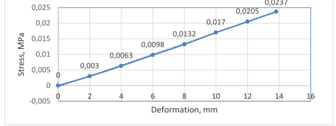
During the analysis of the stressed-deformed state of the glass-fiber sample, a linear relationship is established, shown in Figure 3.4.
Figure 3.4. - Graph of the stress-strain state of a GRP specimen
It was experimentally established that the destruction of a sample from glass fibers occurred in several stages:
- when the stress in the sample reaches 0.0237 MPa, the outer fibers break; - with further loading, the rod is torn in its cross-section (Figure 3.5.).
Figure 3.5. - Fracture of a glass fiber plastic sample
The stress-strain diagram is practically linear up to the destruction of the reinforcement. The characteristics of any composite depend on the materials from which it is made, the location and direction of the reinforcing fibers, and the interaction between the materials (fiber and matrix). The main factors affecting the physical characteristics are: the mechanical properties of the fiber, their orientation, length, shape and composition, the mechanical properties of the polymer matrix, and the adhesion between the fibers and the matrix. The role of the polymer matrix is to transfer stresses between reinforcing fibers and the surrounding structure and protect fibers from environmental and mechanical damage. Interlayer shear is a critical factor for deformable structures. The shear plane is important for torsion loads. The properties of the polymer matrix affect the interlayer shear, as well as the flat shear properties of the composite [23].
0 0,003 0,0063 0,0098 0,0132 0,017 0,0205 0,0237 -0,005 0 0,005 0,01 0,015 0,02 0,025 0 2 4 6 8 10 12 14 16 Str ess, M Pa Deformation, mm
3.2 Testing of the composite reinforcement
with periodic profile for bending
In domestic and foreign practice, glass continuous fibers are used as a reinforcing material for composite materials, which have high strength, resistance to alternating loads and heat shocks, corrosion resistance, and durability [24]. Resins, however, assume the role of a plastic base (matrix). The resin, as a rule, is 25% of the tensile strength of the material.
The tests were carried out on the previously mentioned NTC-13.04.20 "Tearing machine 20 kN", designed for static testing of the strength of materials for axial tension / compression.
When choosing the test model, the mathematical model of the deformation of composite materials on a polymer matrix under harmonic loading conditions was taken into account. This sample, lying on two parallel supports, is bent using a special nozzle until the strength of the element is lost. The sample is loaded in the middle of its span between the supports. A hypothesis has been adopted on the absence of longitudinal layer pressure on each other and the hypothesis of plane cross sections. Tangential stresses from transverse forces are not taken into account in the calculation. The glass-fiber rod with periodic profile undergoes a kinematic action - periodically bends with a fixed deflection ƒ = 1 mm - a rigid loading regime (Figure 3.6.).
Figure 3.6. - Test plan for bending specimens
In determining the stress-strain state of the sample model, two conditions were used: static and dynamic.
The static condition is that the distribution of the normal stresses over the height in all the sections of the sample marked should be such as to ensure the equilibrium condition - the internal moment must be equal to the external moment, taking into account the possibility of the appearance of zones of plastic deformations.
The kinematic condition is that the deflection of the sample at its midpoint in all test cycles must be equal to the preset value of the total deformation ƒ.
reinforcement with periodic profile, taken for bending tests. The samples of the studied three compositions differ among themselves by the type of resin A, B, and C. More clearly, the differences between the resin samples are manifested when bending them than by stretching, and also in determining deformation and elongation. These changes are characteristic in the case of the determination of stresses during the destruction of the gel coating, than in the destruction of the sample itself [25].
Figure 3.7. - Types of tested fiberglass profiles fittings
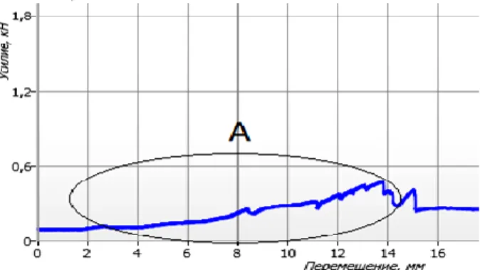
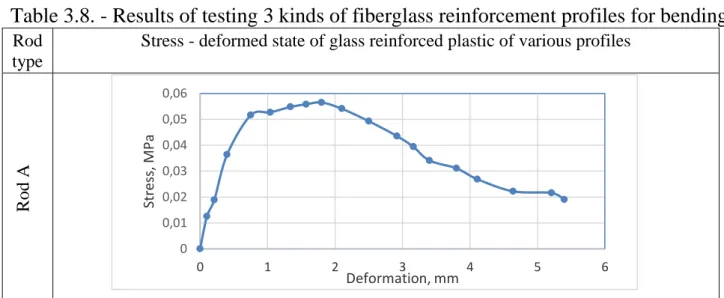
The analysis of the "force-displacement" diagram obtained for each type of the test rod (Table 3.8.) Shows that the nature of the destruction largely depends on the type of profile and its impregnation. The graphs show the sections of maximum forces and displacements of the fiberglass reinforcement with periodic profile during the bending test.
Table 3.8. - Results of testing 3 kinds of fiberglass reinforcement profiles for bending
Rod type
Stress - deformed state of glass reinforced plastic of various profiles
R od A 0 0,01 0,02 0,03 0,04 0,05 0,06 0 1 2 3 4 5 6 Str ess, MPa Deformation, mm
Continuation of the table 3.8. R od В R od С
Destruction in a short bend test always occurs on the tensile surface of the sample, although the test was carried out in such a way that a face subjected to pressure was directed upward. Probably, the destruction is due to the fact that due to changes in the compressible layers changing the position of the neutral axis and, consequently, the number of effective stretchable samples.
Bending failure is a gradual process in which subsequent layers of fiberglass consistently form a "crust", so there is a greater variability in the properties obtained during the bending test.
The pressure of the knife edge of the extensometer somewhat reduces the destructive load of the gel coating at the contact point, making it minimal for any point. Thus, the rupture of the gel coating first occurs at the knife edge. Probably, in all samples the destruction of the gel coating at the point of contact occurs before the final destruction of the sample. When the knife edge penetrates the fracture, its wedge-like action increases the local load in the reinforced layer at this point. Consequently, the additional tensile load is reduced, which is required to cause complete destruction of the sample. Thus, the average tensile stresses will be lower for both specimens, both at rupture of the gel coating and for complete destruction, for specimens whose destruction occurs at points of contact with the clamp of the
0 0,01 0,02 0,03 0,04 0,05 0,06 0 1 2 3 4 5 6 Str ess, M Pa Deformation, mm 0 0,02 0,04 0,06 0,08 0,1 0,12 0,14 0,16 0 1 2 3 4 5 6 Str ess, MPa Deformation, mm
extensometer than for specimens subject to normal destruction [25].
The reinforcing effect of fibers is that the fibers that are stronger and stiffer than the matrix begin to carry the bulk of the load in the composition as soon as their volume fraction in the matrix exceeds a certain critical value [26].
Experimental studies show that when glass fiber reinforced plastic is used, at the beginning of the casing of the reinforcement, the tensile limits are stretched, and subsequently internal longitudinally placed threads enter into operation (Table 3.9.). Table 3.9. - Comparison of destruction of three different types of fiberglass reinforcement with periodic profile.
Rod type
Destruction The location of the break under the microscope R od А R od В
Continuation of the table 3.9.
R
od
С
In sample A, the failure occurred due to the direction of the reinforcing filler, which contains continuous unidirectional fibers oriented along the reinforcing filler web. On the microscope, the breaking of the glass fibers is clearly visible.
In sample B, the destruction of the glass filaments was due to the insufficiently tight pitch of the interlacing of the two glass wools. At the point where the rod breaks, a breakage of the glass fibers is also observed.
In sample C, the rod bent, the destruction occurred over the matrix. The observed glass filaments at the break point remained intact due to the more dense pitch of the weave and the connection of the two glass windrows.
3.3 Detection of the possibility of prestressing
of composite reinforcement with periodic
profile
The modulus of deformation of composite reinforcement is 4-5 times less than that of steel. Therefore, it is advisable to use it only in prestressed structures. There are mainly three methods of pre-stressing concrete structures with discrete composite fittings: tension on the stops, tension on the concrete, continuous winding. The most common method is the tension on the stops. With the help of special devices, the composite reinforcement is stretched to a predetermined value and fixed to the side elements of the metal mold, then concreting and thermal treatment of the concrete are performed to accelerate the hardening. After a set of 70% final strength concrete, the compression force is transferred to the concrete.
Thus, when processing the experimental data presented in Table 3.10., The dependence of the absolute deformations of the composite reinforcement with periodic profile on the load is obtained, which suggests that the possibility of obtaining a prestress is realizable.
Table 3.10. - Dependence of absolute strain on load for composite reinforcement with periodic profile Load at stage Q, kN 1 3 6 9 12 15 18 Elongation Δl, mm 0,0004 0,0013 0,0024 0,0034 0,0045 0,0056 0,0073
On the example of the regression model, one can derive the dependence of the strength of the composite (y), on the volume fraction of the fiber concentration (Vb). This dependence on physical considerations can be considered linear:
y b0 bV1 b (2)
In the matrix entry: XBY (3) To estimate the coefficients of a linear model, changing the filling by volume Q from 1 kN. with a step of 18 kN. The results are represented by the vector:
0.0004 0.0013 0.0024 0.0045 0.0056 0.0073 Y
The calculated matrix, the second column of which defines the experimental conditions: 1 1 1 3 1 6 1 9 1 12 1 15 1 18 X Vector of coefficients: 0 1 b B b (4)
To calculate these coefficients, we find successively the matrix XT: 1 1 1 1 1 1 1 1 3 6 9 12 15 18 T X Matrix XTX: 1 1 1 3 1 6 1 1 1 1 1 1 1 7 64 1 9 1 3 6 9 12 15 18 64 820 1 12 1 15 1 18 T X X
Determinant: det(X X) det 7 64 1644 64 820 T Inverse matrix(𝑋𝑇𝑋)-1 : ( ) 0.49 0.039 0.039 0.0042 T X X Matrix XTY: 0.0004 0.0013 1 1 1 1 1 1 1 0.025 0.0024 1 3 6 9 12 15 18 0.32 0.0045 0.0056 0.0073 T X Y We find B: 0 1 0.49 0.039 0.025 0.00023 0.039 0.0042 0.32 0.00037 b B b
It follows, the linear model estimate is a graph (Figure 3.11.):
0.00023 0.00037 b
y V
Figure 3.11. - Graph of evaluation of the linear model
The performed researches allow to put forward a hypothesis about possibility
0 1 2 3 4 5 6 7 8 0 5 10 15 20 Elon gat ion Δ L, мм * 10 -3 LOAD, KN Rod(0,8802 см2)
of using composite reinforcement with periodic profile in prestressed concrete products. Based on the literary analysis, the results obtained with the help of mathematical design of the experiment and mathematical statistics, it can be noted that with a thermal and mechanical action on the composite reinforcement with the periodic profile, it is possible to achieve sufficient elongation, which is necessary for obtaining a prestress.
The limiting value of the prestress stress σ of the glass-fiber reinforcement with periodic profile is 0.30σ. (Table 3.12.) [26]. Also, with additional processing of special types of resin, the interlacing of the rods will have the property of "memory", which will tend to return the rod to its original dimension, to mechanical and thermal effects.
Table 3.12. - Physical and mechanical characteristics of fiberglass reinforcement with periodic profile 0,30σ with a cross-sectional area of 8 mm.
Limit load P, kN Strength limit σ, MPa Relative elongation Ɛ,% 0 0 0 1 11,4 0,0004 2 22,7 0,0009 3 34,1 0,0013 4 45,4 0,0016 5 56,8 0,002 5,7 63,81 0,0022
In the figure 3.13. the sections of the maximum stresses and deformations of the glass-reinforced reinforcement with periodic profile under tension are displayed.
Figure 3.13. - Limit value of deformations of all components of the glass-reinforced plastic reinforcement with periodic profile, with tension
With the help of microscopy it can be seen that the cracks spread along the path of least resistance, and follow the voids or other defects that they encounter on the way (Figure 3.14.).
0 11,4 24,7 36,1 45,4 56,8 63,81 103,5 0 20 40 60 80 100 120 0 0,0005 0,001 0,0015 0,002 0,0025 0,003 St resses σ, M P a Relative deformations Ɛ,%
Rod of periodic profile Glass roving
Figure 3.14. - Transverse and longitudinal form of fibers fiberglass reinforcement with periodic profile,
after stretching
1 - the upper glass screening, 2 - the lower glass screening;
As can be seen from Fig. 3.14., When the fiberglass reinforcement with periodic profile is stretched, defects on the upper and lower glass windings do not arise after stress removal. Dedicated technological void areas between the two glass windings do not cause internal deformations and microcracks in the rods. The determination of these conditions makes it possible to distinguish three basic states of a composite material, which can be conditionally called initial (undamaged), damaged and destroyed [27].
Coclusion by chapter
1. An important feature of the mechanical behavior of structurally inhomogeneous materials under load is the overcritical deformation stage, as well as numerical modeling methods that allow the medium to be represented in the form of a system of discrete elements and to consider dissipative processes: as multi-step damage to the structure of the model.
2. Several stages can be distinguished during the destruction of composites. At the initial stage, the generation and accumulation of damages occur. The next stage is the merging of individual zones of accumulation of damage with the formation of a sufficiently extended material.
3. When solving the problem of predicting the strength of a composite, first of all, an assessment is made of the conditions under which the process of active accumulation of damages begins at the initial stage of failure, and second, the evaluation of the conditions under which there is a transition from localized accumulation of damage to macroscopic failure material.
4. COMPUTER MODELING OF COMPOSITE
REINFORCEMENT WITH PERIODIC PROFILE
4.1 Creation of a unique periodic profile of
composite reinforcement
In the course of the work, we set out to simulate and test a rod of composite reinforcement with periodic profile. To implement the task, the software products of the ANSYS SpaceClaim, Magics and T-FLEX CAD complexes were used.
In the figures 4.1. - 4.3. general types of simulated reinforcing composite rods are shown, which can be used for reinforcement of products either constructively or with calculation depending on operating conditions. The profile of the reinforcement is formed due to the tension of the rovings on the bobbin, when the tension is weakened, an elliptical profile is formed, and when the tension is increased, a rectangular profile is formed. In Figure 4.3. a zigzag profile is formed as a result of a deviation in the transverse direction of one of the tows, which is used for the production of prestressed cement-concrete structures. Preliminary stress of this composite reinforcement is assumed due to pulling the rod by the amount Δl. The reinforcing composite rod contains two bundles which are subjected to a curl by bypassing one of the tows around the other bundle, forming a loop, then tightening it and repeating the curling process repeatedly. The distinctive features of the modeled reinforcing bar are:
- another form of performance of the elements, namely the reinforcing composite rod, having interlacing places from the filament bundles;
- the mutual arrangement of elements, i.e. places of weaving are located with an equal step between them (adjustable).
- additional processing of rovings with special types of resins that have the property of memory, which will tend to return the rod to its original state, before it is drawn (Figure 4.4.).
The proposed production of reinforcing composite rod provides for the modernization of existing technological lines, or fundamentally new technologies that would allow the formation of a profile without human participation, according to specially written programs. Using the model will increase the reliability of building structures by increasing the bond area of the reinforcing composite rod to concrete and the possibility of obtaining a prestress.
Figure 4.1. - Profile of composite reinforcement of elliptical type
Figure 4.2. - Profile of composite reinforcement of rectangular shape
Figure 4.3. - Profile of composite reinforcement in zigzag shape
Figure 4.4. - Additional roving protection by resin treatment
In Figure 4.4. 1) Roving consisting of threads, 2) Additional roving treatment, 3) The main coating of the rod.
Also, these types of profiles received a positive decision to issue a patent for the utility model "Reinforced composite rod" from March 17, 2017 No. u 20170099.
4.2 Testing of the modeled composite
reinforcement of the profile for tension
Often, simulation simulations completely eliminate the need to conduct full-scale experiments. In the same place, where imitation is not possible without confirmation on physical samples, simulation simulation allows to significantly reduce the number of experiments by selecting the optimal design parameters, thereby reducing the costs for approbation of results or certification of the product. Often, the results of virtual tests give a broader picture of the processes that are happening than a full-scale experiment, providing more opportunities for optimizing and improving performance, while saving considerable time and resources.
In addition, the application of numerical and experimental research methods is practiced, when the results of full-scale tests are supplemented with results of simulation modeling that are unattainable in the field experiment [28]. In this case, the reliability of the results is automatically confirmed by the correlation of the obtained solution with the experimental one.
Tensile tests with non-destructive methods were carried out using the T-FLEX CAD software. As a result of the design, 3D models of the composite reinforcement with periodic profile, presented in Section 3.1, were used in T-FLEX CAD. For the further investigation the elliptical shape was chosen (Figure 4.5.). This type of profile received a positive decision to obtain a patent.
Figure 4.5. - 3D model of the selected composite profile fittings in the program complex T-FLEX CAD
The fragments are executed parametrically, windows of control dialogs are created. This allowed us to accelerate the work on optimizing the geometric dimensions and shape of the structural elements, and significantly accelerate the implementation of strength calculations in the module T-FLEX Analysis. (Fig. 4.6).
When making calculations, the following assumptions and simplifications are accepted:
- the strength of the structure is estimated by the value of the safety factor of equivalent stresses;
- the material of the structure is assumed to be isotropic, the stress concentrators caused by the ideal geometry of the model, and the material defects in the calculation are not taken into account;
- calculation of strength of the structure is carried out at the appropriate voltage at which the plastic deformation of the material begins.
Figure 4.6. - Deformations and tensile stresses experienced by a model of a given profile
The results obtained, illustrated in Figure 4.6., Are comparable with the indices of field trials presented in Table 3.12 (3.3), which confirms the correctness of the specified parameters and configurations during the virtual experiment. The significance of the experimental results can be more significant if it is possible to rely on computer modeling.
Conclusion by chapter
1. The reinforcing composite rods are modeled, which can be used to reinforce the products either constructively or with calculation depending on the operating conditions.
2. On the basis of the constructed 3D-model, the following stages of the experiment were realized: a calculated finite element model was constructed; given contact conditions and loading conditions; Verification calculation of the model; A general evaluation of the structural strength was carried out. No less important is the fact that using T-FLEX CAD it became possible to create a solid prototype of the previously selected rod.
5. PROTOTYPING WITH THE APPLICATION OF 3-D
PRINTING, AS A NEW STAGE IN THE BUILDING
INDUSTRY
5.1 Creation of a prototype of a composite
reinforcement with periodic profile
Technologies that allow you to see a three-dimensional computer model in real volume can not be called very common (although they are already at the level of user and price and availability). The ability to feel this model and interact with it, is still quite small.
Why do we need to take a three-dimensional model of something and make a real object out of it? The first, and most important, in the industry - mainly for rapid prototyping - to see how the model will look in the material. In addition, on the finished model, you can conduct various tests before the final version of the product is ready.
However, prototypes are not all. The next step is rapid production. Already, some 3D printing technologies make it possible to manufacture finished objects from various materials [28].
To create a prototype of the previously designed periodic profile, 3D printing was used at the Mojo installation of Stratasys, installed in the information center of the Polotsk State University. The model was checked for errors and exported to the STL-format by means of Magics Materialise through the 3D-printing dialog (Figure 5.1.). The program optimally orientes the model, divides it into horizontal sections (layers) and calculates the path of the head moving the filament.
Figure 5.1. - Export assembly to STL-format for 3D-printing
The Mojo printer uses QuickPack printers that contain and provide modeling materials and supporting materials to create components using 3D printing (Figure 5.2.). Basics for modeling create a smooth surface on the basis of which models are formed.
3D model specifications and
parameters:
Printable area 127x127x127 mm
The thickness of the layer is not
less than 0.17 mm
The exact name of the
consumable is ABS Plus P430
speed, outer perimeter - 40 mm/s;
filling speed - 100 mm / s;
Figure 5.2. - The Mojo 3D printer software window
Layers are stacked one by one, until the model is completed. If necessary, support elements (support) for the hanging fragments of the model are automatically generated. In Figure 5.3. The result of 3D printing of a prototype of composite reinforcement with periodic profile is presented.
Due to the lack of the possibility of printing a full-scale model, the prototype turned out to be greatly reduced, which does not give a full evaluation of the physical and mechanical behavior of the sample. Based on the REC studies, we indicate the characteristics of plastic for stretching (Table 5.4.) [29]:
Table 5.4. Strength characteristics of the plastic used to create a prototype composite reinforcement periodic profile.
The technology of rapid prototyping has a number of unconditional advantages. It involves the production of prototypes by the method of layer-by-layer stacking of semi-molten polymer filament in accordance with the geometry of the mathematical model of the part developed in the CAD system. The main advantages of this technology are its efficiency and fast implementation, as well as high accuracy of the model elements.
5.2 Modeling of the device for multiple tests of
composite reinforcement with periodic profile
For the manufacture of prestressed structures reinforced with a composite reinforcement with periodic profile in the factory, an obstacle is the absence of gripping devices and equipment. Practice has shown the advantage of wedge clamps in comparison with other types of gripping devices. Prototypes were the developed models of devices for testing composite reinforcement for tension (Figure 5.5. - 5.7.).
Drawing. 5.5. Devices for fixing the ends of composite fittings (Genina E.E., Ph.D.)
Figure 5.6. Device for fastening the ends of composite armatures (Shabanov D.N., Ph.D.) [21]
Figure 5.7. Spatial image of the attachment device ends of composite fittings (Shabanov D.N., Ph.D.) [22]
It is often necessary to confirm the operability or check certain performance characteristics. In such cases, the simplest way to verify the operability and reliability is to create prototypes or mock-ups with a subsequent test in conditions close to real.
Using computer-aided design systems, an end clamp was modeled. This clamp is used in devices where it is necessary to obtain a significant clamping force or change its direction, which allows increasing and changing the direction of the transmitted force. To provide a restraining force, the surface of the wedge inside the clamp should create the necessary resistance on the contact surface resulting from the plastic deformation of the composite reinforcement when it moves relative to the wedges, which complements the friction force.
The developed device (Fig. 5.8 - 5.9.) For the testing of composite reinforcement consists of two plates (1) installed at the ends of the composite reinforcement, inside of which there are wedges (2), compressing the composite reinforcement (3), excluding the possible occurrence of stress concentrators. A feature of the design of the device is the dismantling of the structural elements, which ensures the multiple use of it. The task is to reduce the cost of production of
cement-concrete products reinforced with a composite reinforcement with periodic profile. The use of this device makes it possible to increase the reliability of the results obtained during the test due to the absence of destruction in the clamping points of the rods.
Figure 5.8. - Model of terminal clamps created in software complex ANSYS SpaceClaim
Figure 5.9. - Stress-strain state of the end
clamps created in the software package T-FLEX CAD
Elastic and plastic analytical solutions. At the initial stage (h 0) of indenting a wedge-shaped punch with a flat base can be used to solve the linear elastic pressure problem of a punch with a rectangular base on the half-space [33, 34]:
2 1 E wl F h m v (5),
where E = 210 GPa is the Young's modulus, v = 0.3 is the Poisson's ratio, w = 0.024 m is the width of the truncated wedge, l = 0.033 m is the length of the truncated wedge base, m is the parameter defined as the ratio of the sides of the base (if l / w = 1.375 m = 0.95, Graph 4.10). Equation (5) was obtained by generalizing the solution of the Boussinesq problem to the action of a normal concentrated force on the surface of an elastic half-space. It should be noted that solution (5) was obtained on the basis of the assumption of an infinitesimal mechanics, where small deformations are assumed and the difference between the actual and reference configurations is neglected. In this case, the shape of the wedge surface is not critical, only the
dimensions of the truncated wedge bases are needed. The solution is valid only for very weak indentation forces and, consequently, for shallow depths of penetration (h neglected. When solution (5) is obtained, it is assumed that the contact pressure is uniformly distributed, there was no friction, and h was taken as the average value of the displacement. Such conditions are not of decisive importance, since, in contrast to the solution for a rigid punch (constant displacements and variable contact pressures) is about 8% [33].
Figure 5.10. [29] - The parameter m in equation (5) with respect to base side l / w = 1.375 6 2 210 10 24 33 6836 0.95 1 0.3 F h N
A simplified analytical model was proposed to determine the force of indentation of a nonideal (truncated) wedge punch with symmetrically inclined sides (200).
The next step was the creation of a prototype end clamp for testing and obtaining a prestressed composite reinforcement with a periodic profile. (Figure 5.11.)
Figure 5.11. - Prototype terminal clamp for testing and obtaining prestressed composite reinforcement with
periodic profile
See Figure 5.12. The test of the specimen for tearing is shown, the developed clamping model is used as the end clamps.
5.2 Building 3D printer with the ability to print
composite reinforcement with periodic profile
Due to the high mechanical characteristics, fibrous composites are widely used in engineering as a structural material. An essential advantage of creating a composite reinforcement with periodic profile using a 3D printer is that the technological process for obtaining the final product is combined in time with the manufacture of a composite fixture based on fibrous composites.
As in the case of conventional 3D printers, the principle of the construction printer is based on extrusion. First you need to prepare a mortar, which includes cement, fiberglass, sometimes expanded clay and other materials. Then the printer squeezes this solution through special nozzles, applying it layer by layer on the base, which makes it possible to erect the walls of a small building in just a couple of hours. The printer allows you to quickly "print" all the walls and other structures. The average speed of printing a modern building printer is from seven to ten square. meters per minute. The cost of building a building using a 3D printer can not be specified, since it allows building any configuration, creating architectural elements of almost any complexity, erect walls of any thickness [35].
Concrete houses to ensure high reliability of construction simply can not do without reinforcement. Such a house will crack and crumble over time. We propose, built by the printer of the house, to reinforce the composite reinforcement with periodic profile, also made using 3D printing. Figure 5.13. The model of the enclosing structure made with the help of ANSYS SpaceClaim software is presented.
Figure 5.13. - Fencing structure model
1) The first printing layer; 2) The second layer of printing; 3) Third layer of printing; 4) Composite reinforcement with periodic profile.
The process of erection will be achieved by using simultaneously two devices: one prints the reinforcement, and the other prints the concrete mixture layer by layer. A rapidly solidifying mixture will be extruded through one nozzle or extruder. The technology provides that each new layer of this mixture is squeezed out of the printing device over the previous one, as a result of which a certain structure is formed (Figure 5.14.).
Figure 5.14. - Construction of a 3D building printer
1) Node printing a concrete mixture (nozzle); 2) Printing of wall construction; 3) End clamp for composite reinforcement with periodic profile;
4) Composite rod; 5) Robotic grip for tensioning composite reinforcement with periodic profile.
From the second nozzle or spinneret 3D-printing of the product occurs due to winding the composite roving from the bobbins, then the mechanism forms a periodic profile. Roving passes through porous rollers, which provide impregnation with photosensitive resin (Figure 5.15.). Cold curing occurs under the influence of ultraviolet rays. The result is a finished product: reinforcing mesh, a flat frame or individual rods.
Figure 5.15. - Printing unit for composite reinforcement with periodic profile
1) Printing device for composite reinforcement; 2) Mechanism of tension adjustment of composite reinforcement with periodic profile.
Conclusion by chapter
1. The technology of rapid prototyping has a number of unconditional advantages. It involves the production of prototypes by the method of layer-by-layer stacking of semi-molten polymer filament in accordance with the geometry of the mathematical model of the part developed in the CAD system. The main advantages of this technology are its efficiency and fast implementation, as well as high accuracy of the model elements.
2. With the help of computer-aided design systems, the terminal clamp was modeled. This clamp is used in devices where it is necessary to obtain a significant clamping force or change its direction, which allows increasing and changing the direction of the transmitted force.
3. A simplified analytical model was proposed for determining the force of indentation of a nonideal (truncated) wedge punch with symmetrically inclined sides.
4. The developed technology, which can be used for 3D printing of products reinforced with continuous filaments from the composite, allows the production of reinforcement with periodic profile.
Conclusion
1. New technologies are increasingly affecting the construction industry and are increasingly using innovations that are technically and economically superior to traditional materials. One of the innovative directions in construction is the use of composite reinforcement, instead of traditional metal.
2. The unique technology of production of composite reinforcement allows us to obtain a high-quality building material of a completely new shape, which allowed us to model fundamentally new types of profiles. These profiles received a positive decision to grant a patent.
3. Computer modeling allows you to detect previously unknown properties of a complex system: its structure, dynamics of development, stability, integrity and other required characteristics.
4. The technology of computer modeling and printing has found its application for the production of fast prototypes for the purpose of visualizing conceptual products. The physical characteristics of the produced prototype models are perhaps the main criterion in choosing the rapid prototyping method: they determine the quality of the model, as well as the possibility or impossibility of using a prototype for solving certain tasks. In the future we plan 3D printing of prefabricated elements of the terminal clamp we modeled and carry out a full-scale experiment with their use.
5. Modeled building 3D-printer, is a "robotic building system", created on the basis of additive technologies. The process of "construction" itself looks like the work of an ordinary 3D printer, layer by layer creating a future structure of concrete. We suggest adding new printing units to an existing analogue, which will allow reinforcing the concrete structure with a composite reinforcement with periodic profile.