505
Vitor Gomes1André Tenchini Silva2
https://orcid.org/0000-0003-0925-1159 Luciano Rodrigues Ornelas de Lima3
http://orcid.org/0000-0002-7332-3818
Pedro Colmar Gonçalves da Silva Vellasco4 https://orcid.org/0000-0003-2808-3437
1MSc, Universidade do Estado do Rio de Janeiro -
UERJ, Departamento de Estruturas e Fundações, Rio de Janeiro - Rio de Janeiro – Brasil.
2Professor-Adjunto, Universidade do Estado do Rio
de Janeiro -UERJ, Departamento de Estruturas e Fundações, Rio de Janeiro - Rio de Janeiro - Brasil. [email protected]
3Professor-Associado, Universidade do Estado do
Rio de Janeiro - UERJ, Departamento de Estruturas e Fundações, Rio de Janeiro - Rio de Janeiro - Brasil. [email protected]
4Professor-Titular, Universidade do Estado do Rio
de Janeiro - UERJ, PGECIV – Programa de Pós-Graduação em Engenharia Civil, Rio de Janeiro - Rio de Janeiro - Brasil.
Numerical investigation
of semi-rigid connection
ultimate capacity
Abstract
With the advances in computational analysis techniques and development of new design methods, new interests have arisen in structural engineering. In the last few years, with the increasing numbers of terrorist attacks, the study of robustness, progres-sive structural collapse and ultimate resistance of structures has grown exponentially, with various studies being published all over the world. In order to perform this study through computational analysis, it was necessary to develop a calibrated numerical model capable of representing the behaviour of structures in their final stage of resis-tance. This article presents an evaluation of semi-rigid connections through a numeri-cal model considering the implementation of collapse and damage progression criteria calibrated against experimental tests. Afterwards, a parametric study was developed by varying the bolt diameters and endplate thickness of a flush endplate semi-rigid con-nection. The main parameters and criteria that rules the simulation of flush end-plate joints subject to damage were assessed, allowing that many different kind of studies with similar components could be performed, such as impact, explosion and column loss analysis. As an outcome, the bending moment-rotation curves of these connections are presented and it is shown that those with a larger bolt diameter were able to pro-duce greater rotation, while an increase in the endplate thickness was able to provide a greater bending moment capacity.
Keywords: semi-rigid connection, nonlinear analysis, progressive damage. http://dx.doi.org/10.1590/0370-44672018710031
Civil Engineering
Engenharia Civil
1. Introduction
Structural connections play a key role in the overall behaviour of steel struc-tures. They are responsible for the load transmission between the elements and are often the limiting factors for the ultimate capacity of steel structures, since they correspond to points where there is high stress concentration. It is recognized that semi-rigid connections have an intermediate behaviour between rigid and pinned. The design method for semi-rigid connections proposed by Eurocode 3 (CEN, 2005) is the Component Method, which is based on a simplified model where each of the linking components has its stiffness and yield resistance. The overall behaviour of
the connection in relation to the bending moment versus rotation curve is defined by the interaction between each of these components. However, this method does not consider the ultimate capacity of the materials, considering only that after a re-sistance limit, the materials begin to deform infinitely without ever failing. Furthermore, these do not present strain hardening and resistance gain, whereby it is necessary to carry out further investigation to have the full connection capacity.
With the advent of computers, nu-merical methods also developed greatly and began to be used for common applications in structural engineering. Among these
methods, it is the Finite Element Method (FEM) which uses the concept of structure discretization, allowing an approximate analysis of each small region of the structure and later evaluating the overall response us-ing an interpolation matrix. FEM allowed several structural analyses to be carried out through computational simulations, instead of laboratory tests. If properly cali-brated and verified through experimental investigation, the analyses by FEM can be extrapolated and applied in numerous cases.
explo-2.1 Investigated semi-rigid connection experimental model
The basic beam-to-columncon-nection used to carry out this study cor-responds to the bolted flush endplate type, composed of M20 cl.10.9 bolts and a 15mm thick S275 steel endplate. The column (HEB240) and beam (IPE240) profiles used
are shown in Figure 1 and are made of S275 steel. This joint was studied and tested in laboratory by Lima (2003) and its material properties will serve as basis for the calibra-tion and verificacalibra-tion developed in this study. Lima (2003) performed tensile coupon tests
of the connection components in order to obtain the actual properties of the materials used. With these tests in hand, the yield and rupture stress and elasticity modulus for each component were evaluated and the results obtained are presented in Table 1.
Figure 1
Investigated semi-rigid connection (Lima, 2003).
Coupon fy (MPa) fu (MPa) E (MPa)
Steel S275 (nominal) 275.00 430.00 210000
Beam web 363.43 454.25 200127
Beam flange 340.14 448.24 215222
Column web 372.02 477.30 206936
Column flange 342.95 448.79 220792
Endplate 369.44 503.45 200248
M20 Class 10.9 (nominal) 900.00 1000.00 210000
Bolt 939.67 1018.67 210000
Table 1
Mechanical properties of the connection components.
2.2 Numerical model description
For the development of the numeri-cal model based on ABAQUS software (SIMULIA, 2014), a C3D8R solid element was used, which has reduced integration and eight nodes with three degrees of freedom per node, with translations in the x, y and z directions, respectively. The Poisson coefficient νwas used equal to 0.3 for all types of materials. The M20 cl. 10.9 bolts were used, consisting of head, nut and body (complete thread). The bolt body has been defined through the cross-sectional area of the threaded zone and its length is equal to the thickness of the elements they attach: endplate and column flange. Furthermore, no pretension load was
applied to them and the bolts were con-sidered as being of the High Resistance (HR) type (D’Aniello et. al., 2017).
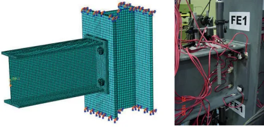
The loading was applied through prescribed displacement at the beam’s centroid, with restricted out-of-plane displacement. With respect to the bound-ary conditions, stress dissipation in the column was verified and the evaluated results showed that the model used with reduced length of the column represented well the real scale model tested by Lima (2003). Additionally, the column ends were considered rigid. The analysed model with respective boundary condi-tions, loading and finite element mesh, as well as an image of the experimental
test are shown in Figure 2. A minimum of three layers of finite elements along plate thickness to avoid shear locking problems and hourglass was used and the meshing technique was assigned to obtain rectangular shapes for elements (D’Aniello et. al., 2017).
507
Figure 2 Numerical and experimental model (Lima, 2003).
2.3 Materials characterization
In order to apply the material proper-ties to the numerical model, a correction to these values is needed, since the actual curveof the material is obtained from a uniaxial test that always considers the initial area of the sample, without taking into account the
area strictness undergone by it. The correla-tion between these nominal and true stresses and strains is presented in Equation 1.
σ
n=
σ
(1+
ε
) e
ε
n=ln (1+
ε
)
(1)where σn= true stress, εn= true strain,
σ = nominal stress, ε = nominal strain. For the characterization of the stress versus strain correlation, a curve based on the quad-linear model was used, according to Figure 3, except for the bolt, where the last presented plateau was not considered due to the rupture occurring under a lower
strain in this material.
The strain parameters followed the criteria proposed by Bradford and Liu (2015) with regard to the yielding and strain harden-ing values of the S275 steel. Regardharden-ing steel rupture, the parameters were defined by the tests performed by Yang and Tan (2009). The rupture strain of the bolts was
defined according to the tests performed by Coelho et al. (2003), not having the last plateau, and only being composed by a tri-linear curve. Thus, the shape of the curve used and the chosen characteriza-tion parameters of the strain points of the quad-linear curve are also reported in Figure 3.
Figure 3 Stress versus characteristic strain quad-linear curve of the calibrated materials.
2.4 Fracture and damage progression criteria
For a structure to be analysed inABAQUS (SIMULIA, 2014) with the use of damage progression, an explicit dynamic analysis is required. This type of analysis is a dynamic procedure, originally developed for high-speed impact events. Simulating a quasi-static analysis through an explicit analysis at a feasible computational cost and produc-ing coherent results requires the use of some numerical techniques that aid in
the resolution of the process, such as the use of the mass scaling technique and reduction of the load application time. The used parameters corresponded to the criteria proposed in literature that relate to the quality of a quasi-static analysis solution through an explicit analysis.
For the damage progression in steel structure numerical simulation, recent studies by several authors have made use of quasi-static analyses using
the proposed criteria, such as Guo et al. (2015), Tay et al. (2016), Forni et al. (2017), Li et al. (2017), Yang and Tan (2013) and Kang et. al (2017). The curve used to characterize the materials behaviour under progressive damage is shown in Figure 4. The value of D cor-responds to the general damage variable (D = 0 to 1.0). After the damage begins, the stress tensor in the material is given by the damage equation:
σ
= (1-D)
σ
where σ is the theoretical stress of the material in the absence of damage.
The point C in Figure 4 for each
material was defined in the ductile rupture criterion, using the fracture stress versus triaxial stress curve according to the
fol-lowing equations based on the studies of Wierzbicki and Werner (1998), Bao (2004) and validated by Wang (2016):
Figure 4
Schematic representation of the elastoplastic behavior of the material under progressive damage (Abaqus, 2005).
The equation (3) describes the material behaviour when there is a com-pression shear fracture and equation (4)
describes the fracture due to the forma-tion of voids inside the material when there is tensile stress, occurring ductile
rupture. Equation (5) refers to cases where pure shear stresses exist. The graph relat-ing these variables is shown in Figure 5.
Figure 5
Dependence of the
equivalent strain to fracture on the triaxial stress (Bao & Wierzbicki, 2004).
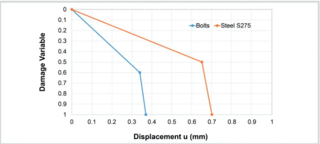
Since bolts have a lower strain capacity, a factor of 0.6 was used in the previous equations. Numerical tests indicated that this was consistent with the results found by Coelho et al. (2003). The damage evolution law (points C-D of the Figure 4 diagram) assumes that the damage is character-ized by the progressive degradation of the material rigidity, leading to its failure. It considers the combination of different damage mechanisms act-ing simultaneously on the same mate-rial and offers the option to describe what occurs after failure, including the possibility of removing elements from the mesh. This behaviour was described using a linear constitutive law, according to Figure 6, in which
are presented the parameters used for the bolts and for the parts formed by the S275 steel.
When the damage variable reach-es the value of 1.0, the corrreach-esponding element of the mesh is eliminated. This law is dependent on the size of the mesh chosen and, due to the impossibility of applying the same re-fined mesh throughout the structure, the calibrated mesh was used only at the points of stress concentration in the connection.
The size of the elements used in the mesh that defined the parameters used according to type of element were: 2 mm for the bolts, 6 mm for the endplate, 8 mm to the beam and 12 mm for the column. To verify the coherence of the
rupture criteria, tensile coupon tests were used to represent those tested in the laboratory, and the stress versus strain curve of these models was veri-fied. The results found were consistent with those presented in the literature previously described.
With these assumptions, the bolts presented a failure at around 12% of strain, which suits the results found by D’Aniello et. al. (2016) and D’Aniello et. al. (2017) for HR and fully thread bolts. For this study, the enhancement effect induced by strain rates under dynamic events is conservatively disregarded, since the main applications were the results here can be applied doesn’t ben-efit too much from this effect (Cassiano
509
Figure 6 Damage evolution law for bolts and other parts of the connection.
2.5 Results
Concerning the comparison of the results, the bending moment (M) applied to the connection was determined through the creation of a free body section in the beam. The rotation was determined from the calculation of the angle formed by two subsequent nodes belonging to the beam centroid just after the yielding
zone. Two analyses were performed with the presented model, one without the use of rupture criteria through a complete nonlinear static analysis, and another considering the damage progression in an explicit dynamic analysis. The results are shown in Figure 7. Using the suggested parameters to transform the analysis
into a quasi-static analysis, the structure behaved satisfactorily, and the results pre-sented by the standard connection in an explicit analysis with progressive damage implemented coincides with that of the nonlinear static analysis without damage. Both results presented a good agreement with the experimental ones.
3. Parametric study
The main objective of the para-metric study performed in this study was to evaluate the bending moment resistance increasing and the
rota-tion capacity of the connecrota-tion using a stronger component than that used in the basic connection. In this way, a parametric study was carried out by
varying the endplate thickness and the bolts diameter. The evaluated models and their respective variables are identi-fied in Table 2.
Figure 7 Comparison between static and explicit analysis with connection damage subject only to bending moment.
Model Plate Thickness (mm) Bolt Size
PL15M20 15 M20
PL15M24 15 M24
PL15M30 15 M30
PL20M20 20 M20
PL30M20 30 M20
Table 2 Parametric study models.
The PL15M20 model corresponds to the standard connection previously mentioned in this study. An explicit analy-sis on damage progression for all models was performed. The bending moment versus rotation curves of all connections are presented in Figure 8.
The PL15M20 model corresponds to the standard connection previously mentioned in this study. An explicit analy-sis on damage progression for all models was performed. The bending moment versus rotation curves of all connections are presented in Figure 8.
(PL15M20).
When analyzing the bending mo-ments resistance Mj,Rd of the connections according to Eurocode 3 (CEN, 2006) and those found in the numerical mod-els, it is seen that the models PL15M20 and PL20M20 obtained a resistance
moment resistant increasing consistent with Eurocode 3 (CEN, 2006). However, the numerical model PL30M20 showed a much higher resistance, which accord-ing to the criterion of the Component Method, should be equal to PL20M20. Although both designs were controlled
model using equivalent T-stubs, used in the component method in Eurocode 3 (CEN, 2006), presents better results for endplates considered thin, whereas for thicker plates the actual behaviour of the connection tends to diverge from the T-stub behaviour.
Figure 8
Moment versus rotation graph of the numerical models.
Figure 9 Deformed after
rupture of numerical models.
Model ID
Eurocode Numerical Model
Mj,Rd (kN.m)
Relative resistance gain
Mj,Rd (kN.m)
Relative resistance gain
Mmáx (kN.m)
Relative resistance gain
PL15M20 74.1 +0.0% 73.9 +0.0% 96.3 +0.0%
PL15M24 88.6 +19.7% 76.6 +3.7% 104.1 +8.1%
PL15M30 96.9 +30.9% 86.3 +16.8% 114.6 +19.0%
PL20M20 84.5 +14.1% 85.1 +15.2% 104.3 +8.3%
PL30M20 84.5 +14.1% 102.3 +38.4% 119.0 +23.6%
Table 3
Initial and relative resistant moment in numerical models.
The connection with the more re-sistant bolt had a less pronounced drop-down in the bending moment capacity, while in those in which the bolt remained unchanged, the rupture and loss of
resis-tance occurred more abruptly. From the results, it was observed that the element that controls the ultimate capacity in the PL15M20, PL20M20 and PL30M20 models were the bolts in tension, and that
their rupture generates an accentuated loss of resistance because they are basically subjected only to the tension stress; the cross-section is all under the same stress, making all the elements of this section fail
511
concomitantly when maximum capacityis reached. In the other connections, the
increase of the bolt section causes the cri-terion governing the dimensioning to
be-come the bending beam, which generates a more gradual reduction of resistance.
4. Conclusions
The ultimate capacity of steel semi-rigid connections was evaluated through the FEM, calibrated based on experi-mental tests by using rupture criteria and damage evolution to characterize the manner the evaluated connections failed. A parametric analysis was performed evalu-ating the influence of the bolt and endplate components on joints with flush endplate when subjected to the bending moment.
The results indicated that the use of larger diameter bolts is essential to increase the final rotation capacity of the evaluated connection, allowing a greater dissipation of the system energy, in addition to grant-ing a greater ductility to the connection. This suggests that, in cases of exceptional events, joints which do not have their rupture dependent on the bolts will prob-ably serve best the demands of external
forces and enable a better redistribution of stresses. The parameters presented in this study, for instance, can help engineers to define the bolt diameter used in flush endplate connections that is not the weak-est component, which will allow better resistances and ductility to the structure in the case of a catastrophic event. Other types of connections and different steel and bolt materials still need validation.
References
ABAQUS, Inc. ABAQUS/Explicit: Advanced Topics. Quasi-Static Analyses. Dassault Systèmes, 2005.
ALASHKER, Y., EL-TAWIL, S., SADEK, F. Progressive collapse resistance of ste-el-concrete composite floors. Journal of Structural Engineering, v. 136, n. 10, p. 1187-1196, 2010.
BAO, Y., WIERZBICKI, T. A comparative study on various ductile crack formation criteria. Journal of Engineering Materials and Technology, v. 126, n. 3, p. 314-324, 2004.
BRADFORD, M. A., LIU, X. Flexural-torsional buckling of high-strength steel beams. Journal of Constructional Steel Research, v. 124, p. 122-131, 2016. CASSIANO, D. et al. Influence of seismic design rules on the robustness of steel
mo-ment resisting frames. Steel and Composite Structures, v. 21, n. 3, p. 479-500, 2016.
CASSIANO, D., D'ANIELLO, M., REBELO, C. Parametric finite element analyses on flush end-plate joints under column removal. Journal of Constructional Steel
Research, v. 137, p. 77-92, 2017.
CASSIANO, D., D’ANIELLO, M., REBELO, C. Seismic behaviour of gravity load designed flush end-plate joints. Steel and Composite Structures, v. 26, n. 5, p. 621-634, 2018.
COELHO, A. M. G., BIJLAARD F. S. K., GRESNIGT N., SILVA, L. Experimental assessment of the behaviour of bolted T-stub connections made up of welded pla-tes. Journal of Constructional Steel Research, v. 60, n. 2, p. 269-311, 2004. COELHO, A. M. G. Characterization of the ductility of bolted end plate
beam-to--column steel connections. Coimbra: University of Coimbra, 2004. 347 p. (PhD
Thesis).
D’ANIELLO, M., CASSIANO, D., LANDOLFO, R. Monotonic and cyclic inelas-tic tensile response of European preloadable gr10.9 bolt assemblies. Journal of
Constructional Steel Research, v. 124, p. 77-90, 2016.
D’ANIELLO, M., CASSIANO, D., LANDOLFO, R. Simplified criteria for finite ele-ment modelling of European preloadable bolts. Steel and Composite Structures, v. 24, n. 6, p. 643-658, 2017.
EUROCODE 1, ENV - 1991-1-7, Actions on structures – Part 1-7: General actions – Accidental Actions. CEN, European Committee for Standardisation, Brussels, 1998.
EUROCODE 3, prEN 1993-1-8, Design of steel structures – Part 1.8: Design of joints (“stage 49 draft”), 2005.
FORNI, D., CHIAIA, B., CADONI, E. Blast effects on steel columns under fire con-ditions. Journal of Constructional Steel Research, v. 136, p. 1-10, 2017.
GOMES, V. R. Análise da influência de ligações semirrígidas na robustez de
pórti-cos metálipórti-cos. Rio de Janeiro: PGECIV- Post-Graduate Program In Civil
Engine-ering, State University of Rio de Janeiro, 2017. 150p. (Dissertação de Mestrado). GUO, L., GAO, S., FU, F. Structural performance of semi-rigid composite frame
shear connections. US Department of Commerce, National Institute of Standards and Technology, 2012.
RODRIGUES, M. C. Modelagem numérica de ligações viga-coluna em aço sob mo-mento fletor e força normal. 178 p. (in Portuguese). Rio de Janeiro: PGECIV- Post--graduate Program In Civil Engineering, State University of Rio de Janeiro, 2009. (Master Dissertation).
SADEK, F. et al. An experimental and computational study of steel moment connec-tions under a column removal scenario. NIST Technical Note, v. 1669, 2010. SIMULIA. ABAQUS Unified FEA (6.14). Dassault Systèmes, 2014.
TAY, C. G., KOH, C. G., LIEW, J. Y. R. Efficient progressive collapse analysis for robustness evaluation of buildings experiencing column removal. Journal of
Constructional Steel Research, v. 122, p. 395-408, 2016.
WANG, K. Calibration of the Johnson-Cook failure parameters as the chip separation criterion in the modelling of the orthogonal metal cutting process. 2016. 103 p. Hamilton: McMaster University, 2016. (Master Thesis).
WIERZBICKI, T., WERNER, H. ‘Cockroft and Latham Revisited. Impact & Crashworthiness Laboratory Report, n. 16, 1998.
YANG, B., TAN, K. H. Experimental tests of different types of bolted steel beam– column joints under a central-column-removal scenario. Engineering Structures, v. 54, p. 112-130, 2013.
YANG, B., TAN, K. H. Numerical analyses of steel beam–column joints subjected to catenary action. Journal of Constructional Steel Research, v. 70, p. 1-11, 2012.
Received: 26 February 2018 - Accepted: 6 May 2018.