Experiment Guide for
the PASCO scientific
Model SE-9634, 9635, and 9636
ESR APPARATUS
®
CAUTION
RISK OF ELECTRIC SHOCK DO NOT OPEN
The lightning flash with arrowhead, within an equilateral triangle, is intended to alert the user of the presence of uninsulated “dangerous voltage” within the product’s enclosure that may be of sufficient magnitude to constitute a risk of electric shock to persons.
CAUTION:
TO PREVENT THE RISK OF ELECTRIC SHOCK, DO NOT REMOVE BACK COVER. NO USER SERVICEABLE PARTS INSIDE. REFER SERVICING TO QUALIFIED SERVICE PERSONNEL.
® i
Table of Contents
Section
Page
® ii
Credits
This manual edited by: Dave Griffith
Copyright Notice
The PASCO scientific Model SE-9634, SE-9635, and SE-9636 Complete ESR System manual is copyrighted and all rights reserved. However, permission is granted to non-profit educational institutions for reproduction of any part of this manual providing the reproductions are used only for their laboratories and are not sold for profit. Reproduction under any other circumstances, without the written consent of PASCO scientific, is prohibited.
Limited Warranty
PASCO scientific warrants this product to be free from defects in materials and workmanship for a period of one year from the date of shipment to the customer. PASCO will repair or replace, at its option, any part of the product which is deemed to be defective in material or workman-ship. This warranty does not cover damage to the product caused by abuse or improper use. Determination of whether a product failure is the result of a manufacturing defect or improper use by the customer shall be made solely by PASCO scientific. Responsibility for the return of equipment for warranty repair belongs to the customer. Equipment must be properly packed to prevent damage and shipped postage or freight prepaid. (Damage caused by improper packing of the equipment for return ship-ment will not be covered by the warranty.) Shipping costs for returning the equipment, after repair, will be paid by PASCO scientific.
Copyright, Warranty and Equipment Return
Please—Feel free to duplicate this manual subject to the copyright restrictions below.
Equipment Return
Should the product have to be returned to PASCO scientific for any reason, notify PASCO scientific by letter, phone, or fax BEFORE returning the product. Upon notification, the return authorization and shipping instructions will be promptly issued.
When returning equipment for repair, the units must be packed properly. Carriers will not accept responsibility for damage caused by improper packing. To be certain the unit will not be
damaged in shipment, observe the following rules:
➀
The packing carton must be strong enough for the item shipped.➁
Make certain there are at least two inches of packing material between any point on the apparatus and the inside walls of the carton.➂
Make certain that the packing material cannot shift in the box or become compressed, allowing the instrument come in contact with the packing carton.Address: PASCO scientific 10101 Foothills Blvd. Roseville, CA 95747-7100
Phone: (916) 786-3800 FAX: (916) 786-3292 email: [email protected]
web: www.pasco.com
®
ESR in Theory
The basic setup for electron spin resonance is shown in Figure 1. A test sample is placed in a uniform magnetic field. The sample is also wrapped within a coil that is connected to an RF oscillator. The smaller magnetic field induced in the coil by the oscillations of the oscillator is at right angles to the uniform magnetic field.
Consider, for the moment, a single electron within the test sample. The electron has a
magnetic dipole moment (µs) that is related to its intrinsic angular momentum, or spin, by the vector equation:
µS=gSµBSh; (equation1)
where:
gs =a constant characteristic of the electron, the g-factor
µB=the Bohr magneton = eh
2me=5.788x10
–9eV G
s =the spin of the electron
h =Planck's constant = 6.582 x 10⁻¹⁶ eV-sec.
The magnetic dipole moment of this electron interacts with the uniform magnetic field. Due to its quantum nature, the electron can orient itself in one of only two ways, with energies equal to E0 ± gsµB/2; where E0 is the energy of the electron before the magnetic field was applied. The energy difference between these two possible orientations is equal to
gsµBB; where B is the magnitude of the magnetic field.
Resonance occurs when the RF oscillator is tuned to a
frequency ν, such that the energy of the irradiated photons,
hν, is equal to the difference between the two possible energy
states of the electron. Electrons in the lower energy state can then absorb a photon and jump to the higher energy state. This absorption of energy effects the permeability of the test sample, which effects the inductance of the coil and thereby the oscillations of the RF oscillator. The result is an observ-able change in the current flowing through the oscillator.
The condition for resonance, therefore, is that the energy of the photons emitted by the oscillator match the energy difference between the spin states of the electrons in the test sample. Stated mathematically:
hν=gSµBB
ESR in Practice
For an electron with only two energy states, in a magnetic field of a given magnitude, it would be necessary to set the RF frequency with considerable accuracy in order to observe resonance. In practice, this difficulty is solved by varying the magnitude of the magnetic field about some constant value. With the PASCO ESR Apparatus, this is done by supplying a small AC current, superimposed on a larger DC current, to a pair of Helmholtz coils. The result is a magnetic field that varies sinusoidally about a constant value.
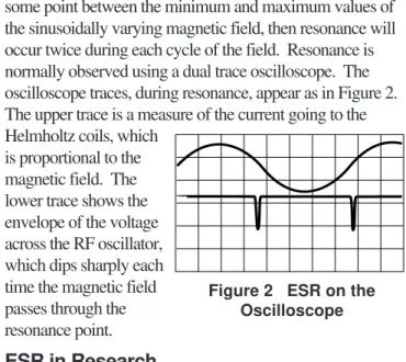
If the RF frequency is such that equation 2 is satisfied at some point between the minimum and maximum values of the sinusoidally varying magnetic field, then resonance will occur twice during each cycle of the field. Resonance is normally observed using a dual trace oscilloscope. The oscilloscope traces, during resonance, appear as in Figure 2. The upper trace is a measure of the current going to the Helmholtz coils, which
is proportional to the magnetic field. The lower trace shows the envelope of the voltage across the RF oscillator, which dips sharply each time the magnetic field passes through the resonance point.
ESR in Research
In research, ESR measurements are considerably more complicated than equation 2 would indicate. The electrons and protons in an atom or molecule form a complicated electromagnetic environment, which is affected by the externally applied magnetic field. The various energy splittings and shifts that show up in ESR measurements can therefore provide sensitive information about the internal structure of the atoms and molecules.
The test sample included with the PASCO ESR Apparatus, DPPH*, is a particularly simple substance for ESR measure-ments. It has an orbital angular momentum of zero, and only one unpaired electron. Therefore, for a given value of the external magnetic field, it has only a single resonant fre-quency. This makes it possible to investigate some of the basic principles of electron spin resonance, without (or before) getting into the more complex world of ESR analysis. (* Diphenyl-Picryl-Hydrazyl)
Introduction
i
RF Oscillator B Test Sample AmmeterFigure 1 ESR Diagram
® f
1000 V +12V
–12V 0
Additional Equipment Needed:
If you're using the SE-9636 Complete ESR System,
you'll need the following additional equipment:
• a DC ammeter capable of measuring up to 3 A
(such as PASCO's SB-9599)
• a dual trace oscilloscope (such as PASCO's SE-9533)
• connecting wires with banana plug connectors
If you're using the SE-9635 Basic ESR System, you'll need the following additional equipment:
• Frequency Meter (to 130 kHz) (such as PASCO's SB-9599 Universal Multimeter)
• SF-9584 Low Voltage AC/DC Power Supply
(or an equivalent supply providing a 10 volt, 3 amp DC output and a 0 - 4 volt, 1 amp AC output)
• Power Supply providing ± 12 VDC
• DC Ammeter (0 - 3 amp) (PASCO Model SB-9599)
Included Equipment
The ESR Apparatus is available in three separate pack-ages (see Figure 3):
• The ESR Probe Unit (SE-9634) includes: The Probe Unit with
base-Three RF Probes and a DPPH sample in a vial The Passive Resonant Circuit
The Current Measuring Lead for the Probe Unit
• The ESR Basic System (SE-9635) includes: The ESR Probe Unit (SE-9634)
A pair of Helmholtz Coils with bases The ESR Adapter (SE-9637)
• The Complete ESR System (SE-9636) includes: The ESR Probe Unit (SE-9634)
A pair of Helmholtz Coils with bases The Control Unit
The ESR Equipment
Helmholtz Coils with bases
B 1
1 2
2 f/MHz
0 10V U0
0 5V Umod
0 90°
ϕ
1
2 0…10V–
Umod 0…5V 0…90°
ϕ Y
X
I 3Amax
Control Unit
ESR Adapter (SE-9637)—included in the ESR Basic System, but not in
the Complete ESR System RF Probes (3):
75 - 130 MHz 30 - 75 MHz
13 - 30 MHz Probe Unit
with base
DPPH sample
Current Measuring Lead for the Probe Unit
Passive Resonant
Circuit
ESR Probe Unit (SE-9634)
ESR Basic System (SE-9635)
Complete ESR System (SE-9636)
®
• Oscilloscope (dual trace) (PASCO Model SE-9533)
• Circuit components:
capacitors: 1000 µF, 25 V; and 0.1 µF
potentiometer (100 kΩ)
connecting wires
If you're using the SE-9634 ESR Probe Unit, you'll need the same equipment as is required with the Basic ESR System, except that you will also need:
• SE-9637 ESR Adapter (or a junction box of your own making—see Appendix)
• a pair of Helmholtz coils.
About the ESR Apparatus
The Probe Unit
The ESR Probe Unit (Figure 4) is the heart of the ESR apparatus. It contains an RF oscillator with a built-in signal amplifier, and a 1000:1 frequency divider. The frequency divider allows the RF frequency, which is in the MHz range, to be measured using a standard kHz frequency meter.
The frequency and amplitude of the RF signal can be controlled using the knobs shown in the figure. The range of frequencies provided by the oscillator depends on which RF Probe is being used. This is because the inductance of the probe determines, in part, the induc-tance of the oscillator circuit. See Figure 3 for the frequency range associated with each probe.
Normally the Probe Unit is plugged into the Control Unit, which provides all necessary operating voltages. How-ever, it can also be connected to separate laboratory instruments using the ESR Adapter, or a home made
adapter. See Setup with the Basic ESR System for details.
Probe Unit Technical Data:
Power Requirements: ±12 V, 175 mA
Frequency ranges: 13 - 130 MHz depending on RF Probe (see Figure 1)
Voltage across the RF Probe: 6 V peak-to-peak at 13 MHz and maximum amplitude
ESR signal: 1 - 6 V depending on frequency
Frequency divider: 1000:1
Frequency output for digital counter: TTL
DC current output: 100 µA approximately
Test substance: Diphenyl-Picryl-Hydrazyl (DPPH)
The Control Unit
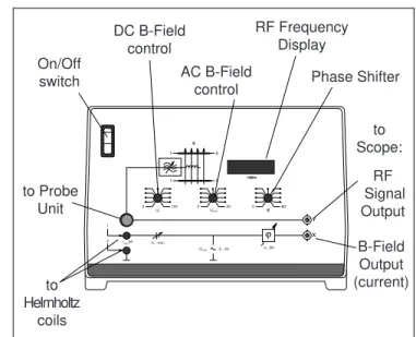
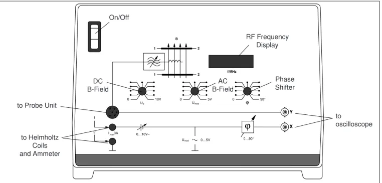
The Control Unit provides most of the instrumentation needed to use the ESR Probe Unit. The front panel controls are explained in Figure 5. The Control Unit serves three functions:
➀ it supplies the voltages needed to drive the Probe Unit
and the Helmholtz coils;
➁ it provides a digital readout of the RF oscillations
pro-duced by the Probe Unit;
➂ it provides outputs for a dual trace oscilloscope. One
output is proportional to the current in the RF oscilla-tor, and is used to observe the resonance pulses. The other output is proportional to the current that is sup-plied to the Helmholtz coils, and indicates the magni-tude of the magnetic field.
B 1 1 2 2 f/MHz 0 10V U0 0 5V Umod
0 90°
ϕ
1
2 0…10V–
Umod 0…5V 0…90°
ϕ Y
X
I 3Amax
On/Off switch
DC B-Field control
AC B-Field
control Phase Shifter RF Frequency Display RF Signal Output B-Field Output (current) to Probe Unit to Helmholtz coils to Scope:
Figure 5 ESR Control Unit
the DPPH Sample fits inside the Probe
Frequency
control Amplitudecontrol
On/Off switch
Supply and signal voltages: connect to Control Unit or ESR Adapter Socket for current measuring lead:
connect to an ammeter to measure RF current without an oscilloscope
the RF Probes plug
in
®
Helmholtz Coils
The Helmholtz coils provide a highly uniform magnetic field in which to place the sample material for the ESR measurement. They should be connected in parallel and placed so that the separation between them is equal to the radius (see Figure 7). When this is the case, the magnetic field in the central area between the two coils is highly uniform, and is equal to the value shown in Figure 7.
➤NOTE: There is an inherent phase shift between the current in the Helmholtz coils and the voltage signal going to the oscilloscope. This shift is caused by the inductance of the coils. The Control Unit includes a phase shifter that lets the user compensate for this delay, so the magnetic field and the resonance pulses can be observed with their proper phase relationship.
The Control Unit operates on a line voltage of 110, 130, 220, or 240 VAC, 60 Hz. See the Appendix for information about adjusting the unit for the proper line voltage.
B=µ0 4 5
3 2N Ir;
µ0= 1.256 x 10⁻⁶ (v•s/A•m) N = turns in each coil = 320 I = current through each coil 2R
R
➤IMPORTANT: Current to each of the Helmholtz Coils should never exceed 3A. There-fore, if they are connected in parallel, the total current to them should never exceed 6 A.
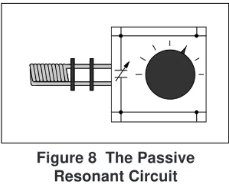
The Passive Resonant Circuit
The Passive Resonant Circuit can be used to demonstrate resonant energy absorption in a non-quantum system. It is just an LC circuit with an adjustable capacitance. It replaces the test sample and the Helmholtz coils in the ESR experiment. See the Appendix for details on using the Passive Resonant Circuit.
Figure 7 The Helmholtz Coils
f 1000
V +12V
–12V 0
Figure 6 ESR Adapter
Control Unit Technical Data:
Power Requirements: 120 or 240 VAC; 60 Hz
Fuse: 1.6 A, 220 V (slo-blo) for 120 VAC
0.8 A, 220 V (slo-blo) for 240 VAC
Magnetic Field Supply: 0 - 10 VDC; 0 - 5 VAC; maximum current 3 A (not overload protected)
Phase Shifter: 0 - 90°
Digital Frequency Display: 4 digits
ESR Adapter
If you are not using the Control Unit, the ESR Adapter can be used to connect the Probe Unit to the necessary power supply, frequency meter, and oscilloscope. See the
section, Setup with the Basic ESR System, for details of
the connections. See the Appendix if you would like details for building your own adapter.
®
Required Equipment
To peRForm ESR experiments with the Complete ESR System, you'll need the following additional equipment:
• a DC ammeter capable of measuring up to 3 A
• a dual trace oscilloscope
• connecting wires with banana plug connectors.
Setup
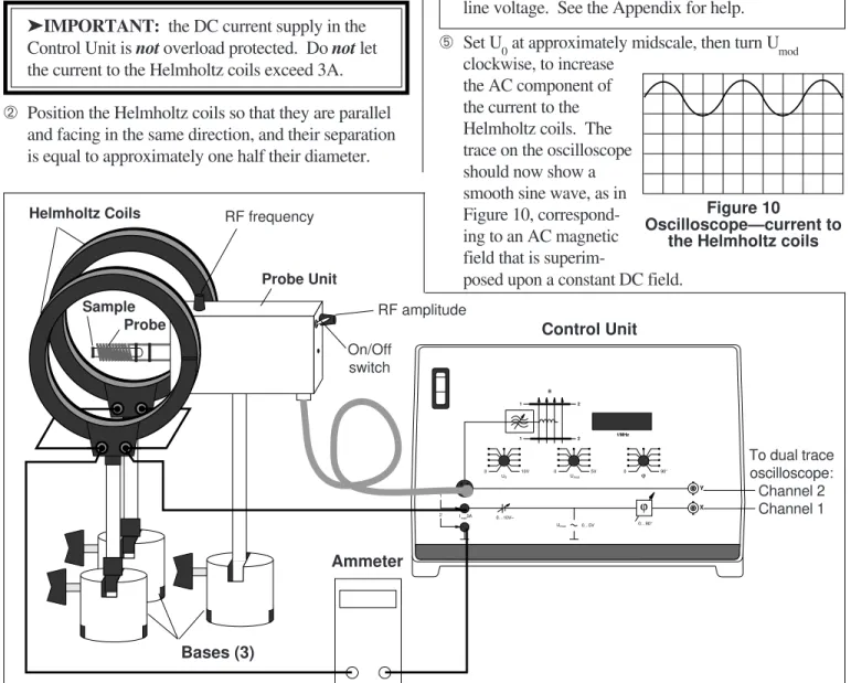
➀ Connect the Helmholtz coils to the Control Unit, as
shown in Figure 9. (The coils should be connected in parallel—terminal A to terminal A, and Z to Z.) Con-nect an ammeter in series, as shown, to monitor the current to the coils.
➤IMPORTANT: the DC current supply in the
Control Unit is not overload protected. Do not let
the current to the Helmholtz coils exceed 3A.
➁ Position the Helmholtz coils so that they are parallel
and facing in the same direction, and their separation is equal to approximately one half their diameter.
Figure 9 Setup using the Control Unit
Setup with the Complete ESR System
B 1
1
2
2 f/MHz
0 10V
U0
0 5V
Umod
0 90°
ϕ
1
2 0…10V–
Umod 0…5V 0…90°
ϕ
Y X
I 3Amax
Control Unit
Probe Unit
Bases (3)
RF frequency
On/Off switch
Ammeter
Helmholtz Coils
Probe
Sample RF amplitude
To dual trace oscilloscope: Channel 2 Channel 1
Figure 10
Oscilloscope—current to the Helmholtz coils
➂ Connect the X output of the Control Unit to channel 1
of a dual trace oscilloscope. Set the oscilloscope con-trols as follows:
Sensitivity: 1 or 2 V/div Sweep Rate: 2 or 5 ms/div Coupling: DC
➃ Set Umod, the center knob on the Control Unit, to zero,
then slowly vary U
0, the left knob, from 0 to 10 V and
observe the trace on the oscilloscope. It should be a clean, straight line, showing that the DC component of
the current to the Helmholtz coils is constant. (U0
controls the DC current going to the Helmholtz coils.)
➤NOTE: If the oscilloscope trace is not straight, your Control Unit is probably not set for the proper line voltage. See the Appendix for help.
➄ Set U0 at approximately midscale, then turn Umod
clockwise, to increase the AC component of the current to the Helmholtz coils. The trace on the oscilloscope should now show a smooth sine wave, as in Figure 10, correspond-ing to an AC magnetic field that is
®
Figure 12 the Oscillo-scope Display
If you see no resonance pulses, slowly vary Umod or the
RF frequency, until you do.
Your traces may not be symmetrical, as they are in Fig-ure 11. This is because of the inductance of the Helmholtz coils, which causes the current through them, and therefore the magnetic field they produce, to lag the voltage that drives them. You can compensate for this delay by adjusting j, the Phase Shifter control knob, until the traces are symmetrical. When sym-metrical, the traces properly reflect the relationship between the modulating magnetic field and the resonant pulses.
ESR in the X-Y Mode
ESR is often observed with the oscilloscope in the X-Y mode. For this mode of observation, connect the X and Y outputs of the Control Unit to the X and Y in-puts of the oscilloscope, respectively. In this mode, the horizontal displacement of the trace indicates the magnitude of the magnetic field between the
Helmholtz coils. The vertical displacement indicates the signal from the
Probe Unit.
As before, two reso-nance pulses can be observed since the magnetic field passes through the correct value twice each cycle. By adjusting the Phase
Shifter, the two peaks can be brought into coinci-dence. The resulting trace will appear as in Figure 12.
➅ Connect the Y output of the Control Unit to channel 2
of the oscilloscope. Set the oscilloscope controls for channel 2 as follows:
Sensitivity: 0.5 or 1 V/div Coupling: DC
➆ Connect the Probe Unit to the Control Unit, as shown in
Figure 9.
⑧ Plug the medium sized RF Probe into the Probe Unit,
and insert the sample of DPPH into the coil of the probe.
⑨ Turn on the Probe Unit by flipping the On/Off switch to
the up (I) position. Then turn the Amplitude knob on the Probe Unit to a medium setting.
➉ The frequency meter on the Control Unit should now
indicate the frequency of the RF oscillations. Adjust the Frequency control knob on the Probe Unit to pro-duce an output of approximately 50 MHz.
Set Umod to about the 4th position above zero (at about
the 11 o'clock position).
Increase U0 from zero to
a medium value, so the Helmholtz coil current is about 1.0 A. The oscillo-scope traces should now look as in Figure 11. The channel 1 trace
shows the current to the Helmholtz coils, which is pro-portional to the magnetic field produced by the coils. The channel 2 trace shows the envelope of the voltage across the RF oscillator, with the pulses showing the points of resonance absorption.
CH1: B-Field
CH2: ESR Probe
Figure 13 Using the Control Unit B 1 1 2 2 f/MHz 0 10V U0 0 5V Umod
0 ϕ 90°
1
2
0…10V–
Umod 0…5V 0…90°
ϕ
Y
X
I 3Amax
On/Off AC B-Field DC B-Field Phase Shifter RF Frequency Display to oscilloscope to Probe Unit
to Helmholtz Coils and Ammeter
®
Required Equipment
To perform ESR experiments with the Basic ESR System, you'll need the following additional equipment:
• Frequency Meter (to 130 kHz) (such as the SB-9599)
• SF-9584 Low Voltage AC/DC Power Supply
(or equivalent supply providing a 10 V, 3 A DC output, and a 0 - 4 V, 1 A AC output)
• Power Supply providing ± 12 VDC
• DC Ammeter (0 - 3 amp) (such as the SB-9599)
• Oscilloscope (dual trace) (such as the SE-9533)
• Circuit components:
- capacitors: 1000 µF, 25 V; and 0.1 µF
- potentiometer (100 kΩ)
- connecting wires
Setup
➀
Connect the Helmholtz coils in parallel, as shown inFigure 14. (Connect terminal A on one coil with terminal A on the other, and likewise connect Z to Z.)
➁
Position the Helmholtz coils so that they are paralleland facing the same direction. The separation between the coils should be approximately equal to their radius. This arrangement produces a highly uni-form magnetic field around the center point between the two coils.
➂
Connect the power supplies, ammeter, oscilloscope,and circuit components to the Helmholtz coils as shown in Figure 15.
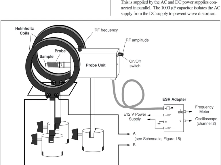
Circuit Explanation: The Helmholtz coils require a small AC current superimposed on a larger DC current. This is supplied by the AC and DC power supplies
con-nected in parallel. The 1000 µF capacitor isolates the AC
supply from the DC supply to prevent wave distortion.
Setup with the ESR Basic System
Figure 14 Setup Using the Basic ESR System
f 1000
V +12V
–12V 0
A
B ±12 V Power
Supply
Frequency Meter
Oscilloscope (channel 2)
Probe Unit
ESR Adapter Helmholtz
Coils
Sample Probe
RF frequency
RF amplitude
On/Off switch
®
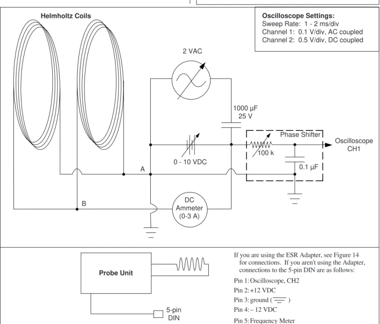
Because of the inductance of the Helmholtz coils, the current in the coils is out of phase with the voltage that is observed on the oscilloscope. To correct this, a
100 kΩ variable resistor and a 0.1 µF capacitor are
used to shift the phase of the voltage that is displayed on the oscilloscope. This allows the experimenter to adjust the phase between the oscilloscope traces, so that the AC current to the Helmholtz coils and the ESR resonance pulses appear symmetrical, which in reality, they are.
➃
Turn on the power supplies. Adjust the DC supply toprovide approximately 1 amp to the Helmholtz coils. Set the output of the AC supply to about 2 volts.
With the oscilloscope controls set to the values shown in Figure 15, channel 1 of the oscilloscope will show the current to the Helmholtz coils, except for the phase
shift caused by the induction of the coils. The trace should be a simple sine wave. (If you switch channel 1 to DC coupling, it should show an AC voltage superimposed on a DC voltage.)
➄
Connect the Probe Unit to the ESR Adapter, andcon-nect the Adapter to the power supply, frequency meter, and oscilloscope, as indicated in Figure 14. (If you aren't using the ESR Adapter, the connections to the Probe Unit are as shown in Figure 15. If you wish to build your own adapter box, see the Appendix.)
➤NOTE: The Probe Unit contains a frequency divider, so that the frequency of the signal sent to the frequency meter is actually a factor of 1000 less than the frequency of the RF oscillations. Because of this, your frequency meter need only measure accurately into the 130 kHz range.
Figure 15 Schematic for Setup without Control Unit
Phase Shifter 2 VAC
1000 µF 25 V
0 - 10 VDC
0.1 µF
5-pin DIN
Oscilloscope CH1
B
A
If you are using the ESR Adapter, see Figure 14 for connections. If you aren't using the Adapter, connections to the 5-pin DIN are as follows:
Pin 1: Oscilloscope, CH2 Pin 2: +12 VDC Pin 3: ground ( ) Pin 4: – 12 VDC
Pin 5: Frequency Meter 100 k
Oscilloscope Settings:
Sweep Rate: 1 - 2 ms/div Channel 1: 0.1 V/div, AC coupled Channel 2: 0.5 V/div, DC coupled
Helmholtz Coils
DC Ammeter
(0-3 A)
®
➅ Insert the medium-sized RF Probe into the connectors
on the Probe Unit, and turn on the Probe Unit. Adjust the frequency to about 50 MHz (50 kHz on your fre-quency meter) and the amplitude to a midrange value. Then insert the test sample into the RF Probe and place the probe and sample in the center of the Helmholtz coils, with the axis of the Helmholtz coils perpendicular to the sample (see Figure 14). The oscilloscope traces should now appear approximately as in Figure 16.
➆ If you don't see the
resonance pulses, slowly vary the DC current to the Helmholtz coils, or vary the RF frequency,
until you do. Figure 16 ScopeDisplay
Figure 17 Scope Display
Whether you are using the Complete ESR System or the ESR Basic System, the same technique is used for making measurements.
➀
Setup the apparatus as described in the appropriatesection.
➁
Adjust the RF frequency and the DC current to theHelmholtz coils until you locate the resonance pulses.
➂
Adjust the phase shifter so that the resonance pulsesare symmetric with respect to the oscilloscope trace that shows the current to the Helmholtz coils.
➃
Refine the adjustment of the DC current until theresonance pulses occur when the AC component of the current to the Helmholtz coils is zero.
To do this:
a. Make sure that channel 1 of the oscilloscope (the trace showing the current to the Helmholtz coils) is in the AC coupled mode.
b. Using the oscilloscope controls, ground the input to channel 1, zero the trace, and then unground the input.
c. Adjust the DC current. As you do, notice how the resonance pulses move closer together or farther apart. Adjust the DC current, and the phase shifter if necessary, until the pulses occur just when the AC current to the Helmholtz coils is zero. (This is most accurately accomplished if you adjust the vertical position of the channel 2 trace so that the bottom of the resonance pulses are just at the zero level of the channel 1 trace.)
With these adjustments, the oscilloscope traces should appear as in Figure 17. Everything is set for making ESR measurements. Since the current has
been adjusted so that the resonance pulses occur when the AC current to the coils is zero, the current to the Helmholtz coils at reso-nance is just the DC value indicated by the ammeter. The resonant
frequency is equal to the value on the Control Unit display (or the value indicated by your frequency meter multiplied by 1,000).
➄
Measure the RF frequency and the DC current. Thenvary the current and find the new resonance fre-quency. Do this for several values of the frefre-quency.
➅
The magnitude of the magnetic field between theHelmholtz coils is directly proportional to the current supplied to the coils. You can determine the magni-tude of the field using the following equation (easily derived from the Biot-Savart Law):
B=µ0 45 3 2
N Ir;
where:
µ0= 1.256 x 10⁻⁶ Vs/Am
N = number of turns in each coil
r = the radius of the Helmholtz coils (which is equal to their separation when they are properly arranged)
I = current passing through the coils.
➆
If you are using the test sample of DPPH, you cannow determine the g-factor for the electron using the
equation hν=gSµBB (see the Introduction for an
ex-planation of the equation).
®
Appendix
Using the Passive Resonant Circuit
The Passive Resonant Circuit can be used to demonstrate the principles of ESR using a classical (non-quantum) electromagnetic system. Set up the Probe Unit as for a standard ESR measurement, using the medium induc-tance probe coil. Instead of using the Helmholtz coils and the test sample, position the Passive Resonant Circuit as in Figure A1. To observe resonance absorption, tune the Probe Unit and the Resonant Circuit to the same fre-quency. This simple demonstration shows how energy from the RF oscillator can be absorbed by a resonant system that is tuned to the same frequency.
➤NOTE: For a slightly simpler setup than is used for standard ESR measurements, you can use the Current Measuring Lead to connect the Probe Unit to a Ammeter (see Figure A1). This eliminates the need for an oscilloscope. You will be able to see the drop in current in the ammeter when resonance is achieved.
You may also find it useful to show how the current drop in the RF oscillator corresponds to oscillations within the Passive Resonant Circuit. You can do this by connecting a voltmeter (1 volt scale) across the terminals of the Passive Resonant Circuit.
The Control Unit
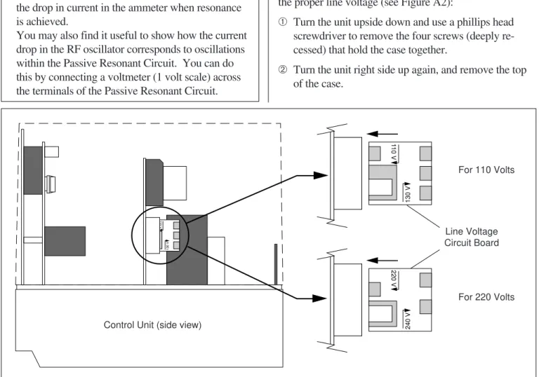
Setting the Line Voltage
The Control Unit can be used with a line voltage of 110 V, 130 V, 220 V, or 240 V. To set the Control Unit for the proper line voltage (see Figure A2):
➀ Turn the unit upside down and use a phillips head
screwdriver to remove the four screws (deeply re-cessed) that hold the case together.
➁ Turn the unit right side up again, and remove the top
of the case.
110 V
130 V
240 V
220 V
110 V
130 V
For 110 Volts
Figure A2 Setting the Line Voltage for the Control Unit
For 220 Volts
Control Unit (side view)
Line Voltage Circuit Board
Probe Unit i
V
Voltmeter ( 1 V)
to Control Unit or ESR Adapter Passive Resonant
Circuit
Figure A1 Setup for Using the Passive Resonant Circuit
®
➂ Pull the line voltage circuit board from its socket and
replace it so that the arrow for the proper voltage faces out toward the side of the control unit and points in toward the socket. (Figure A2 shows the proper ori-entation of the circuit board for 110 V and 220 V.)
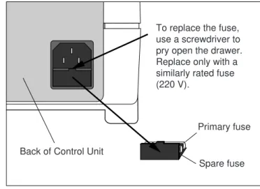
Replacing the Fuse
The fuse for the Control Unit is located in a pullout drawer just underneath the socket for the power cord (see Figure A3). Replace only with a similarly rated fuse:
- 1.6 A, 220 V (slo-blo) for 120 VAC - 0.8 A, 220 V (slo-blo) for 240 VAC
Building Your Own ESR Adapter
You can purchase an ESR Adapter from PASCO scien-tific (Model number SE-9637). However, if you prefer to build your own, the connections are shown in Figure A4.
pin 1
pin 5
+12 V
0 V
–12 V
To Frequency Meter
(BNC connector)
To Oscilloscope (BNC connector) Probe Unit
DIN Connector
Figure A4 Schematic for the ESR Adapter
Banana Plug Connectors
To replace the fuse, use a screwdriver to pry open the drawer. Replace only with a similarly rated fuse (220 V).
Back of Control Unit
Primary fuse
Spare fuse
®
®
Technical Support
Feed-Back
If you have any comments about this product or this manual please let us know. If you have any suggestions on alternate experiments or find a problem in the manual please tell us. PASCO appreciates any customer feed-back. Your input helps us evaluate and improve our product.
To Reach PASCO
For Technical Support call us at 1-800-772-8700 (toll-free within the U.S.) or (916) 786-3800.
email: [email protected]
Tech support fax: (916) 786-3292
Contacting Technical Support
Before you call the PASCO Technical Support staff it would be helpful to prepare the following information:
• If your problem is with the PASCO apparatus, note:
Title and Model number (usually listed on the label).
Approximate age of apparatus.
A detailed description of the problem/sequence of events. (In case you can't call PASCO right away, you won't lose valuable data.)
If possible, have the apparatus within reach when call-ing. This makes descriptions of individual parts much easier.
• If your problem relates to the instruction manual, note:
Part number and Revision (listed by month and year on the front cover).