Preparation and Growth Characterization of Al
2Cu Phase Crystal with the Single
Orientation Under Directional Solidification
Ka Gaoa,b* , Yueyang Xua,b, Wenzheng Songa,b, Li Guanc, Mingliang Lic, Kewei Lid, Xiaoqin Guoa,b,
Rui Zhanga,b
Received: May 29, 2018; Revised: August 13, 2018; Accepted: August 17, 2018
Through decreasing the sample size, the regular faceted rectangular Al2Cu phase crystal was
prepared under directional solidification. Effects of sample size on the microstructure morphologies
and orientations of intermetallic Al2Cu phase crystal growth at 10 µm/s have been characterized and
investigated. The transverse-section microstructure of primary Al2Cu phase crystal transited from
L-shaped pattern to regular faceted rectangular pattern with a single preferred orientation at [001] direction with sample size decreasing. By using the serial sectioning technique, the three-dimensional
(3D) microstructure of Al2Cu phase in 0.45 mm sample was observed as rectangular parallelepiped. Moreover, the faceted interfaces of Al2Cu phase crystal were determined as {110} planes. Based on growth characteristics of the Al2Cu phase crystal, a growth mode in different sizes samples under
directional solidification was proposed. The experimental results show that a regular microstructure with preferred single orientation can be achieved in small-size sample during directional solidification.
Keywords: Solidification, Intermetallic alloys and compounds, Regular faceted rectangular, Orientation, Crystal growth.
*e-mail: [email protected]
1. Introduction
The intermetallic compounds crystal with crystalline anisotropy may grow along preferred growth direction
under directional solidification, and could result in various
microstructure morphologies1-4. However, in directional
solidification, thermal gradient and solute segregation often cause the thermosolutal convection in liquid, resulting in these crystals growth without any apparent preferred orientations. To avoid the thermosolutal convection effect and control
crystal to grow well, Trivedi et al.5,6 had prepared the sample
by reducing sample size and investigated the effect of sample size on microstructure during directional solidification.
They found that with sample size decreasing, the Al2Cu phase microstructure morphology could be well controlled
because of the weakened thermosolutal convection. But they
had not discussed and analysed whether or not the crystal
orientation changes in their work. Until recently, few works have been done to investigate the effect of sample size on crystal orientation. However, microstructure morphology was decided by its orientation. And the intermetallic Al2Cu
phase has crystalline anisotropy, thus it could be displayed
various growth patterns with specific growth direction during
different directional solidification conditions1. Therefore, to
well control the Al2Cu crystal growth, it is urgently necessary
to study its orientation by reducing the sample size. However, heavy convection was still present even if the sample diameter of Al-Cu hypereutectic alloy had been decreased to 0.8 mm 7. In order to control Al
2Cu crystal
well growth with a single preferred orientation in Al-Cu
hypereutectic alloy, it is essential to further reduce the sample
diameter. Nevertheless, due to capillary effect, liquid could not fill in a thin container, which causes that the method
introduced by Trivedi6 was limited. Thus it needs to develop
a new method to prepare the small (thin thickness) sample to control crystal growth well.
In this work, a method is firstly developed to realize the smaller size solidified samples, in which micro thermosolutal convention solidification can be achieved. On the basis, the aim of this work is to prepare regular faceted rectangular
Al2Cu phase with the single orientation, then investigate the
effect of sample size on the microstructure morphology and
orientation of Al2Cu phase crystal under directional solidification.
The experimental results show that the small directionally solidified samples can obtain regular microstructure with a
single growth direction of Al2Cu phase crystal.
aZhengzhou University of Aeronautics, Zhengzhou, 450015, P.R. China
bHenan Key Laboratory of Aeronautical Material and Application Technology, Zhengzhou, 450015, P.R.
China
cTU Bergakademie Freiberg, Freiberg, 09599, Germany
2. Experimental Methods
2.1 Materials
Al-40 wt.% Cu alloy was prepared using 99.99% purity
aluminium (Aluminum Corporation of China Limited,
China) and 99.5% purity copper (Copper Corporation of
China Limited, China) in a vacuum induction melting
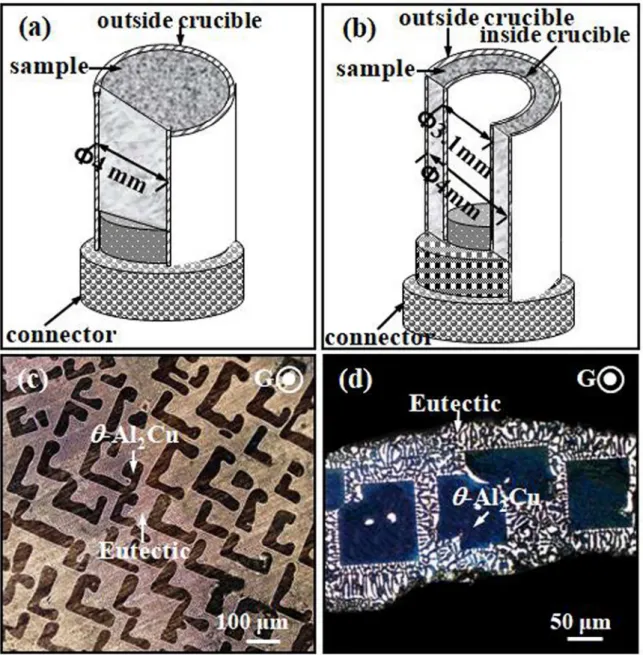
furnace. Figure 1(a) presents the schematic drawing of the 4 mm sample with a single high-purity alumina crucible (Beijing Ding Sheng Technology, China) under directional solidification. Different with that in the single crucible, the device for the 0.45 mm sample preparing was designed
based on the method introduced by Trivedi et al.6 as shown
in Figure 1(b). The sample was embedded in the middle
of two high-purity alumina crucibles (inner crucible with a diameter of 3.1 mm and outer crucible of 4 mm). In this case, the average thickness of the sample is only 0.45 mm, which is greatly reduced compared with 0.8 mm introduced
by Lee et al.7. Moreover, the thickness of sample can be
further reduced by increasing the size of the inner crucible.
2.2 Sample preparation
Directional solidification experiments were carried out using a Bridgman vertical vacuum furnace described
elsewhere8. The thermal gradient was measured using a Φ0.5
mm NiCr-NiSi thermocouple. In directional solidification
process, the sample was heated by a graphite heater at
700 ºC and then kept isothermal for 20 minutes so as to homogenize the original ingot composition. Subsequently,
the sample was moved downwards at pulling velocity of 10
µm/s. When the directional solidification distance reached 50 mm, the sample was quenched into a liquid Ga-In-Sn pool to keep the S/L interface.
2.3 Characterization
The directionally solidified samples were sectioned
horizontally and vertically, respectively, and etched with
the agent of H2O (46 mL) + HNO 3 (3 mL) + HF (1 mL)
to photograph its microstructures by the scanning electron
microscopy (SEM, JSM-6390A). The high resolution transmission electron microscopy (HRTEM, Tecnai G2 F30)
was employed to observe the faceted interface of Al2Cu
phase. In addition, the orientations were investigated by means of the X-ray powder diffraction (XRD, D/max-3) and the electron back-scattered diffraction (EBSD) in scanning electron microscopy (SEM, Zeiss Supra 55) equipped with the Channel 5 EBSD system (HKL Technology-Oxford instrument).
In this work, Materialise's interactive medical image
control system (Mimics) software and the serial sectioning
technique were applied to reconstruct the three-dimensional
(3D) microstructure images of the primary Al2Cu phase.
The 3D serial sectioning procedure working principle is
similar to the internal structure of the human body analyzed
layer by layer by CT in medicine. If we want to obtain the
whole microstructure of sample, we should scan it layer by layer and then reconstruct the each layer information by the
Mimics system. Firstly, the surface of the sample was milled off with a step-size, then the microstructures of the polished samples were revealed and the first layer information was obtained. Nest repeat the first step and milling off the surface of the sample with the stayed step-size to obtain the second
and more other layers information by the serial sectioning
technique. After obtaining the all layers information of sample, finally, the obtained images and information were transferred into Materialise's interactive medical image control system, then fixed position, edited, and reconstructed into three-dimensional models.
3. Results and Discussions
3.1 The temperature gradient measured in
different sizes samples
In this experimental section, the temperature gradient
(G) was measured using the NiCr-NiSi thermocouple at the
pulling velocity of 10 µm/s. Figure 2 shows the schematic of the temperature gradient measurement and the experimental date in different size samples. The NiCr-NiSi thermocouple was embedded inside the crucible of 4 mm in Figure 2(a) and the inner crucible with a diameter of 3.1 mm in Figure 2(b), respectively. Under directional solidification process,
the sample was preheated by a graphite heater at 700 ºC for
20 minutes. Then the NiCr-NiSi thermocouple and the sample were moved downwards synchronously. At the same time,
the temperature curve was measured by the thermometric
instruments shown in Figure 2(c). The thermal gradient was calculated by the Eq. (1)9:
(1)
where TL is the liquidus temperature, TS is the solidus temperature, V is the pulling rate, and t is the time of the
melt cooling from the liquidus temperature to the solidus temperature. Through calculating, the thermal gradient in 4 mm sample was about 236 K/cm, which was less than the value of 255 K/cm in 0.45 mm sample. This result proves that when the thickness of sample is thinner, its thermal gradient is higher. However, the difference value of thermal gradient measured between different sizes samples is least (i. e. to about 8.5% of the thermal gradient in 4 mm sample). It can be deduced that the effect of the samples size (thickness)
decreasing on the temperature gradient during directional
solidification is small.
In fact, the minimal changes about the temperature gradient in different sizes samples could not result in more effects on the morphology evolution. Trivedi et al.10 found
that with the diameter of Al-4%Cu alloy sample decreasing, the crystal morphology had little differences only the size decreased. It indicates that the temperature gradient may only affect the characteristic size of microstructure, such as the dendrite arm spacing, eutectic spacing and so on. On the other hand, a large number of previous works11-13 were investigated the preferred orientation of the super alloys
during directional solidification process. The preferred
Figure 2. The schematic of the temperature gradient (G) measurement
in different sizes samples: (a) the 4 mm sample, (b) the 0.45 mm sample, and (c) the experimental date of temperature in different sizes samples.
G
T
LV t
T
S$
-orientation was the [001] direction, which had not been changed whether in higher or lower temperature gradient. The effect of thermal gradient on dendrite orientation may be also small. This means that the growth changes of the
Al2Cu phase caused by the changing of thermal gradient
can be neglected in this work.
3.2 Directionally solidified microstructures (2D
and 3D) in different sizes samples
Figure 1(c) and (d) show the growth patterns (2D) of Al-40%Cu alloy in different size samples under directional solidification. It is well known that the solidification
microstructures of the alloy consist of primary intermetallic
θ-Al2Cu and eutectic (Al/Al2Cu) based on the Al-Cu phase
diagram. In 4 mm sample, the primary Al2Cu phase crystal
could be clearly distinguished from the eutectic in Figure 1(c). The Al2Cu phase displayed regular faceted L-shaped
and I-shaped patterns14 in the transverse section.
When sample size decreased to 0.45 mm, the primary
Al2Cu crystals were regularly aligned in single layer and
exhibited faceted rectangular patterns15 shown in Figure 1(d),
which is different from the microstructures in Figure 1(c).
Moreover, the size of the Al2Cu crystal was smaller than that
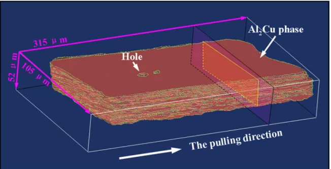
in 4 mm sample. By using the serial sectioning technique16,17,
the three-dimensional (3D) microstructure of the primary
Al2Cu phase in 0.45 mm sample was reconstructed during
directional solidification shown in Figure 3, which provides
a novel way to deeply understand the crystal growth of the
solidified phases. The Al2Cu phase crystal was observed
rectangular parallelepiped in 0.45 mm sample and grew along the pulling direction. The 2D morphologies of Al2Cu phase
in transverse section displayed the rectangular patterns by cutting the 3D microstructure along transverse section shown
in Figure 3, which is consisting with the result in Figure 1(d).
Interestingly, there were some smooth holes in the
three-dimensional microstructures of Al2Cu phase crystal shown in
Figure 3. Different with the forming reason about re-melting of solidification front or dissolving of the local crystal
surface in the presence of impurities18, these smooth holes
were eutectic microstructures transformed from remaining
liquid in the centre of the rectangle pattern of the Al2Cu phase
crystal. Actually, these holes filled by eutectic microstructures were also found in the two-dimensional microstructures in Figure 1(d). The above results indicated that the Al2Cu phase
crystal displayed different microstructures solidified under the different conditions, for example in different size samples.
3.3 Faceted interface of Al
2Cu phase determined
in different sizes samples
We employed TEM to investigation the facets of Al2Cu
phase in different size samples. the L-shape and I-shaped patterns in 4 mm sample were observed in Figure 1(c). The
two patterns of Al2Cu phase were also bounded by faceted
planes. Figure 4(b) is an TEM image of the microstructure of red region and Figure 4(c) is a selected-area electron diffraction pattern (SAED) from the Al2Cu phase in Figure
4(b). The (001) zone axis was paralleled with the direction of electron beam. By indexing the diffraction patterns, the four diffraction patterns in Figure 4(c) can be identified to be
the {110} facets of Al2Cu phase. The relationship between
{110} facets and surface of L-shape morphology can be identified in Figure 4(d).
From the three-dimensional (3D) microstructures, the
primary Al2Cu phase crystal displayed regularly rectangular parallelepiped and had obviously faceted characterization
in 0.45 mm sample. The smooth hole was filled by eutectic microstructures shown in Figure 5(a), which was introduced before in this paper. Figure 4(b) is an enlarged HRTEM
image of the microstructure of red region. The black area structure can be identified as Al2Cu phase in Figure 5(b). A
selected-area electron diffraction pattern of Al2Cu phase is
shown in Figure 5(c). By indexing the diffraction patterns,
the {110} facets of Al2Cu phase in Figure 5(c) can be clearly
identified, which is identical to the previous work18. Moreover,
this diffraction patterns show the faceted characteristic as the rectangle pattern in Figure 5(d). The bounded surfaces
of regular rectangle pattern about Al2Cu phase crystal were
{110} facets.
In addition, Hamar et al.19 obtained the growth morphology
of Al2Cu crystal assuming the growth rates to be proportional
to the attachment energy. Basing on their works, it could be
also inferred that the regular rectangle pattern of Al2Cu phase
crystal was bounded by {110} facets in transverse section.
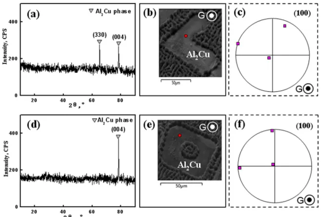
3.4 Orientations in different sizes samples
With sample size decreasing, Al2Cu phase crystal
patterns became more regular and uniformly arranged;
seen from Figure 1(d). The growth behaviour may be also responsible for those regular microstructures. For clarifying
the crystallographic characteristic of the Al2Cu phase crystal, XRD was used to measure its growth orientation, as reported
by Huang et al.20. Generally, Al
2Cu phase crystal grew freely
from various crystal planes (110), (310), (200), (211), (112),
(202), and (420) (21, 22). Only two peaks of the phase, (330)
and (004), appeared in 4 mm sample, as shown in Figure 6(a). When sample size was further decreased to 0.45 mm, the crystal plane (330) disappeared and only the diffraction intensity of the peak (004) increased in Figure 6(d), which was higher than that in 4 mm sample. Apparently, Al2Cu
phase had a strong and single preferred orientation at (004) direction. The single preferred orientation was consistent with the regular rectangular patterns of the phase in Figure 1(d) and Figure 3.
Further, the crystal orientations of the primary Al2Cu
phase in different sizes samples were investigated by the EBSD analysis. Figure 6(b)-(c) and 6(e)-(f) show the EBSD results in the transverse section and corresponding (100)-pole figures of the Al2Cu phase in different sizes samples,
respectively. The L-shaped pattern and rectangular pattern could be observed in Figure 6(b) and (e), respectively. From the pole figure, it is easy to deduced that both for 4 mm and 0.45 mm samples, the application of directional solidification
had oriented the primary Al2Cu phase with the [001]-crystal
direction, which was along the heat flow direction. Moreover,
with the sample size decreasing, the orientation of Al2Cu
phase was further concentrated to the heat flow direction, which agrees well with the XRD results in Figure 6(a) and (d). The above results proved that a regular microstructure
with a single growth direction might be obtained in small
size sample.
Basing on the above results, the growth mode of Al2Cu
phase crystal under different growth conditions is proposed.
Al2Cu phase crystal belongs to tetragonal crystal system
and possesses anisotropy. Normally, Al2Cu phase will
grow along disorder direction depended on the interfacial
energy (surface energy, boundary kinetics, etc) under free solidification as shown in Figure 7(a). Then it will be formed
various microstructure morphologies without any special
orientation. Actually, its growth directions are directionless pointed to the surrounding. In directional solidification, solidified microstructure can be well controlled and the
orientation was selected well resulted from the convection
Figure 4. (a) Transverse-section SEM image of rectangle pattern about Al2Cu phase crystal in 4 mm sample, (b) the HRTEM image
of the red region from (a), (c) the selected-area electron diffraction pattern (SAED) from (b): [001] crystal, and (d) {110} facets image.
Figure 5. (a) Transverse-section SEM image of rectangle pattern about Al2Cu phase crystal in 0.45 mm sample, (b) the HRTEM image
Figure 6. The 4 mm sample under directionally solidified in transverse section: (a) XRD patterns, (b) the position of EBSD testing, and (c) (100)-pole figure of Al2Cu phase; the 0.45 mm sample under directionally solidified in transverse section: (d) XRD patterns, (e) the
position of EBSD testing, and (f) (100)-pole figure of Al2Cu phase.
Figure 7. Growing schematic illustration of Al2Cu phase crystal: (a) under free solidification, (b) in 4 mm sample under directional
solidification, and (c) in 0.45 mm sample under directional solidification.
influence. The convection caused the change of atomic stacking direction and velocity at the interface, resulting in the interfacial energy changing. So some growth directions were disappeared. Similar with the super alloys growth during directional solidification, the directional heat flow becomes the dominant factor affecting the crystal growth11-13.
The [001] and [110] directions were the preferred growth directions, but there were perpendicular directions. The [001] direction was the c-axis direction closing the heat flow direction and [110] direction was the normal direction of side boundary surrounding. So the Al2Cu phase crystal
growth process was including two almost simultaneous
actions, such as growing taller along [001] direction nearly the heat flow direction and growing in width direction along [110] direction in Figure 7(b). However, due to the [110] direction not so concentrate to the heat flow direction shown in Figure 6(c) and not be perpendicular to the solid/liquid
interface, Al2Cu phase grew slightly tilted. Then the part of
crystal was re-melted and formed the L and I-shaped patterns not the regular rectangular pattern. When the sample size decreased, there has the diffusion environment. Due to the
direction will be along the crystal plane direction with
highest attachment energy and the [001] direction will be the dominant one. And in our work, the preferred orientation of
Al2Cu phase crystal was only [001] direction and it would
further concentrate to the heat flow direction in Figure 7(c). The [001] growth direction in the 0.45mm was more isotropic and growth along this direction was to be faster. The phase
morphology would be more regular, which is corresponding
with the three-dimensional (3D) microstructures in Figure 3.
The regular microstructure with a single orientation can be
achieved by reducing the sample size.
In this study, a 0.45 mm thickness sample was adopted to
prepare, and the regular faceted Al2Cu phase crystal growth
in Al-40%Cu hypereutectic alloy was investigated. The three-dimensional (3D) microstructures of Al2Cu phase in
small size sample became more concentrative. The results show that the solidified microstructure and the orientation
selection can be well controlled in a much smaller sample
under directional solidification.
4. Conclusions
The microstructures and orientations of intermetallic Al2Cu phase crystal in directionally solidified Al-40%Cu
hypereutectic alloy with different size crucibles were investigated. With the sample size ranging from 4 mm to 0.45
mm, the primary Al2Cu phase crystal in transverse section
changed from L-shaped patterns to faceted regular rectangular patterns. By using the serial sectioning technique, the
three-dimensional (3D) microstructures of Al2Cu phase in 0.45
mm sample was observed as rectangular parallelepiped. The
faceted interface of Al2Cu phase dendrite was {110} planes. The orientation of Al2Cu phase became more concentrative
and was along the heat flow direction. A single preferred orientation at (001) was obtained.
5. Acknowledgments
This work was financially supported by the fund of the Key of Scientific Research Project of Henan Provincial (No.162102210241) and the Higher Education of Henan Provincial (No.17A430007).
6. References
1. Li X, Ren ZM, Fautrelle Y, Zhang Y, Esling C. Effects on high magnetic fields on the microstructure of Al-Al2Cu eutectic. Materials Letters. 2010;64(23):2597-2600.
2. Tao X, Wang Z, Lan C, Xu G, Ouyang Y, Du Y. Exploring phase stability, electronic and mechanical properties of Ce-Pb intermetallic compounds using first-principles calculations.
Journal of Solid State Chemistry. 2016;237:385-393.
3. Lee TH, Sim MS, Joo SH, Park KT, Jeong HG, Lee JH. Effect of intermetallic compound thickness on anisotropy of Al/Cu honeycomb rods fabricated by hydrostatic extrusion
process. Transactions of Nonferrous Metals Society of China. 2016;26(2):456-463.
4. Choudhury SF, Ladani L. Local shear stress-strain response of Sn-3.5Ag/Cu solder joint with high fraction of intermetallic compounds: Experimental analysis. Journal of Alloys and Compounds. 2016;680:665-676.
5. Trivedi R, Mazumder P, Tewari SN. The effect of convection on disorder in primary cellular and dendritic arrays. Metallurgical and Materials Transactions A. 2002;33(12):3763-3775. 6. Lee JH, Liu S, Miyahara H, Trivedi R. Diffusion-coefficient
measurements in liquid metallic alloys. Metallurgical and Materials Transactions B. 2004;35(5):909-917.
7. Lee JH, Liu S, Trivedi R. The effect of fluid flow on eutectic growth. Metallurgical and Materials Transactions A. 2005;36(11):3111-3125.
8. Qu M, Liu L, Tang FT, Zhang J, Fu HZ. Effect of sample diameter on primary dendrite spacing of directionally solidified Al-4%Cu alloy. Transactions of Nonferrous Metals Society of China. 2009;19(1):1-8.
9. Jordan RM, Hunt JD. Morphological observations of the eutectic-dendrite breakdown in the Al-Al2Cu system. Journal of Crystal Growth. 1971;11(2):141-148.
10. Trivedi R, Liu S, Mazumder P, Simsek E. Microstructure development in the directionally solidified Al-4.0 wt% Cu alloy system. Science and Technology of Advanced Materials. 2001;2(1):309-320.
11. Versnyder IF, Shank ME. The development of columnar
grain and single crystal high temperature materials through
directional solidification. Materials Science and Engineering. 1970;6(4):213-247.
12. Epishin AI, Nolze G. Investigation of the competitive grain growth during solidification of single crystals of nickel-based superalloys. Crystallography Reports. 2006;51(4):710-714. 13. Zhao XB, Liu L, Yu ZH, Zhang WG, Zhang J, Fu HZ. Influence
of directional solidification variables on the microstructure and crystal orientation of AM3 under high thermal gradient. Journal of Materials Science. 2010;45(22):6101-6107.
14. Gao K, Song SJ, Li SM, Fu HZ. Characterization of microstructures
and growth orientation deviating of Al2Cu phase dendrite at
different directional solidification rates. Journal of Alloys and Compounds. 2016;660:73-79.
15. Gao K, Li SM, Xu L, Fu HZ. Effect of solidification rate on microstructures and orientations of Al-Cu hypereutectic alloy in thin crucible. Crystal Research and Technology. 2014;49(2-3):164-170.
16. Sidhu RS, Chawla N. Three-dimensional microstructure characterization of Ag3Sn intermetallics in Sn-rich solder by serial sectioning. Materials Characterization. 2004;52(3):225-230.
17. Lieberman SI, Gokhale AM, Tamirisakandala S. Reconstruction of three-dimensional microstructures of TiB phase in a powder metallurgy titanium alloy using montage serial sectioning.
18. Singh H, Gokhale AM, Mao Y, Tewari A, Sachdev AK. Reconstruction and Quantitative Characterization of Multiphase, Multiscale Three-Dimensional Microstructure of a Cast Al-Si Base Alloy. Metallurgical and Materials Transactions B. 2009;40(6):859-870.
19. Hamar R, Lemaignan C. Facetting behaviour of Al2Cu during solidification. Journal of Crystal Growth. 1981;53(3):586-590. 20. Huang N, Hu AM, Li M. Influence of texture of Cu on the growth of
Cu-Sn intermetallic compounds. Materials Letters. 2013;109:8-11.
21. Belgacem CH, Fnaiech M, Loubradou M, Lay S, Bonnet R. HRTEM observation of a <113> (θ) low angle tilt boundary in the Al-Al2Cu(θ) eutectic composite. Physica Status Solidi A. 2002;189(1):183-196.
22. Bonnet R, Loubradou M. Crystalline Defects in a B.C.T.
Al2Cu(θ) Single Crystal Obtained by Unidirectional
![Figure 5. (a) Transverse-section SEM image of rectangle pattern about Al 2 Cu phase crystal in 0.45 mm sample, (b) the HRTEM image of the red region from (a), (c) the selected-area electron diffraction pattern (SAED) from (b): [001] crystal, and (d) {11](https://thumb-eu.123doks.com/thumbv2/123dok_br/16314830.718721/5.765.66.379.96.409/figure-transverse-section-rectangle-pattern-selected-electron-diffraction.webp)