Abstract—This paper presents a study and design of a robotic fish that imitates bladder function of a fish by focusing on the orientation performance. The main focus of the research is to develop the robotic fish which can perform the natural orientation of a fish. Not only the turning maneuver of the robotic fish takes place in horizontal plane or vertical plane at a time, but also in both of horizontal and vertical planes simultaneously. The orientation of the robot is conducted by anti-weight equilibriums, which are installed near the center of gravity of the robot, to maintain the desired position. The collection of robotic orientations is operated by designed apparatus including 4 anti-weight objects which attached with servo motors for rolling and pitching. The implementation of the proposed robotic fish shows a good performance as well as illustrate the robustness of such a robotic framework.
Index Terms—Artificial intelligence, intelligent robots, motion control
I. INTRODUCTION
UMAN have been impressed by the diversity of habitual characteristic and incredible swimming ability of the fish for decades. Great effort has been focused on the high efficiency and maneuverability of its propulsion and maneuvering mechanism. The splendid characteristics of real fishes attract robotics researchers greatly in recent years. A numbers of animal-like aquatic robots have been researched in the past. Thus, developing a robotic fish with a new level of performance close to actual fish has been challenging.
Engineers and Sciences have been inspired to study how aquatic animals swim and maneuver for long time [1], [2]. In 1960, Lighthill [8] presented the research of observation of a swimming fish. In 1995, the aquatic robot named RoboTuna which mimicked the bluefin tuna was developed by a research team at MIT. Kato established fish robot with apparatus of pectoral fin motion in 1998 [9]. Morgansen adapted the carangiform-like movement of aquatic animal into robotic fish to help with trajectory stabilization in 2002 [10]. In 2011, Nilas [3] presented fish robot which could change swimming behavior within BCF movement. In the
Manuscript received December, 2015; revised January, 2016.
T. Ratanajaratrod is a Master Degree student in Department of Instrumentation and Control Engineering, Faculty of Engineering, King Mongkut's Institute of Technology Ladkrabang, Bangkok Thailand 10520. (e-mail: [email protected]).
P. Nilas, Ph.D. is with Department of Instrumentation and Control Engineering, Faculty of Engineering, King Mongkut's Institute of Technology Ladkrabang, Bangkok Thailand 10520. (e-mail: [email protected]).
same year, a research team from UTE [4] developed the pseudo fish bladder which stored water inside the robot. This mechanism allows their robotic fish to change swimming depth via remote controller. In 2014, Lee and Ahn [5] designed spherical robot by using hybrid pendulum. The robot can maneuver by changing the center of gravity and the moment of a force. Despite a number of previous works, the depth control and orientation of the aquatic robots have been a great challenge. The depth and orientation play an important role in mimicking the fish robot maneuver. This paper utilizes anti-weight balances to develop orientation mechanism. The anti-weight balances are the result of moment of force, buoyancy, and changing center of gravity. The paper studies and designs the bladder-like system for depth, position and orientation of the robot. This paper is organized as in the following. First section is mentioned an introduction and inspiration of the work, including relevant academic researches, to provide ideas for creating new robotic fish. Second section is described a background of fish swimming mechanism and mathematical model of fish locomotion. Third section is shown physical theories and orientation mechanisms employed in this research. Forth section is shown designing concept and implementation of the robotic fish. Relevant topics are included; mathematical models, hardware and software designs. Fifth section is shown experimental results as graph between tilt angle and servo arm position. The last section is described an experimental conclusion and ways to improve the future work.
II. SWIMMING CONCEPT OF FISH
A. Forces of Swimming Fish
Movement of fish organism affects the direction of swimming and maneuvering. To overcome water friction, fish generates force from many tiny muscles and exerts it against the medium, surrounding water. To swim through the water, the forces in swimming can be analyzed into 2 main forces [3].
The forces in swimming can be generated from the extensibility and contractility of muscle relatively. A combination of vectors between lateral force (FL) and thrust force (FT) gives forward locomotion. The former force, FL, becomes an energy loss. It provides lateral movement that helps fish maneuver in the water. The latter force, FT, mainly provides forward locomotion.
B. General Form of BCF Swimmer
The extensibility and contractility of muscle are a
An Implementation on 3D Positioning
Aquatic Robot
T. Ratanajaratrod and P. Nilas
locomotive pattern that commonly found in species of fish. This method of movement is classified under body and/or caudal fin mode (BCF). Four locomotive forms in BCF mode are categorized as the following:
--Anguiliform, the entire body of fish performs full wave. Its body structure is non-rigid. Therefore, the whole body is flexible. Found in eel, tadpole, etc.
--Subcarangiform, the entire body of fish performs full wave like Anguiliform but the amplitude of the movement occurs in half of the body. Found in trout, cod, etc.
--Carangiform, sine wave occurs only at the last part of a body length. One-third of a body length is rigid. Because the more rigid part appears, the more fish tends to swim faster than the previous. Found in salmon, mackerel, etc.
--Thunniform, the most efficiency pattern appears in fish. The last part of a body length only performs sine wave. The whole body of fish is almost rigid except a caudal fin. It propels itself by exerting force against the surrounding water. Found in tuna and mammal in sea.
C. Mathematical Model of Fish Locomotion
The method of movement using in the robotic fish is based on Nilas mathematical model [3]. Body length of fish was divided into body modules, each module imitates part of fish in BCF mode. Servo motor is a joint that link body modules together. Mathematical model, which imitates fish locomotion, is designed to control amplitude and frequency of servo motor. It gave a more natural robot locomotion so the robot can change locomotive pattern flexibly. Mathematical models can be expressed as follows
ft
B
TA
K
A
n
asin
2
n1
(1)
actual
actual iA
A
A
K
TA
max
/
(2)where An is the propelling coefficient, Ka is the adjusting
amplitude of sine wave, f is the frequency of propelling, Β is the time lag of nth joint, Ki is the turning angle coefficient,
Amax is the maximum amplitude of turning angle, Aactual is
the actual amplitude of turning angle.
III. DESIGN CONCEPT
A. Moment of Force and Buoyancy
Orientation mechanism is installed inside the robotic fish. It employs a mechanical part which can adjust the center of gravity of the robot. The system applies a weight that attached on servo arm which could rotate horizontally. The servo arm length d and weight mg illustrated in Fig. 1
Fig. 1. Servo motor with the arm length d
In addition, several foam balls are also installed inside the
robot to buoy the fish body. The moment of a force appears in the system causes the robot body inclined from the horizontal plane. This moment of a force directs downward which is opposite to a buoyancy. When the servo arm rotates, weight has been changed its position. Thus, the center of gravity has shifted from the original position. The buoyancy also helps the robot stay afloat in the water. The size and shape of the robot affect the overall system. In this case, the moment of a force causes the robot inclined.
B. Tilt Angle of Robot Body
MEMS motion sensor, which installed inside the robot body, is used to measure tilt angle of the overall system. A reference axis depends on an installation of the sensor.
(a) (b)
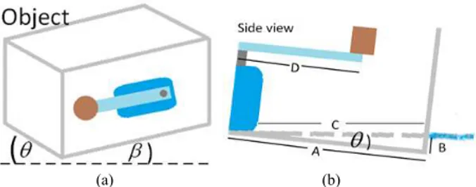
Fig. 2. (a) Tilt angle of the robot body in X-Z plane (θ) and Y-Z plane (β) (b) Side view of the robot body that contain servo motor
Supposing that the angle θ and β are the angle of inclination in X-Z and Y-Z plane respectively, as shown in Fig. 2(a). Its values are both measured from the MEMS motion sensor. Tilt angle, however, can be calculated by hand. In Fig. 2(b), tilt angle θ is the part of a right triangle. First, A is adjacent to angle θ that is measured from pivot point to the other end of the robot. Next, C is the hypotenuse that is measured horizontality. Finally, B is the opposite side of angle θ that is measured by depth level of immersed robot body. Depth level B is subject to change due to length D. The servo arm can rotate back and forth and may be gone from observer sight depending on the servo arm position. On the other hand, the moment of a force from weight is still has an effect on the system by affecting another plane, Y-Z. The equations for the tilt angle in terms of finding θ in X-Z plane can be expressed as
2 2 2
A
B
C
(3)A
B
tan
(4)
B
A
1tan
(5)The tilt angles which appear in the system have two important factors to consider: the buoyancy and the moment of a force. To calculate tilt angle, the constant κ must be inserted to the equation accordingly. The constant κ represents the effect of a weight on the servo arm and a container size and shape. The angle of inclinationβ in Y-Z could be calculated by using the similar concept and equation.
0 to 180 degrees, which means that orientation of the robot in the working sphere has been limited. An effective way to solve the problem is to increase the number of servo motors. The patterns used in this paper are shown in the following sections:
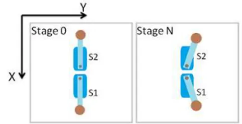
--Parallel patterns, two servo motors are established at the center of a waterproof robot body. They are parallel to each other and move in the same direction. A starting position of servo arms is set to 90 degrees. At the end of the length of servo arms have been attached weights mg as shown in Fig. 3
Fig. 3. Parallel pattern of servo motors and the position of servo arms during the starting stage and the Nth stage
During the starting stage, servo arms are set to 90 degrees. The moments of a force from weights combines into a vector sum that moves in the downward direction. Therefore, the summation of all forces is the reciprocal of the maximum tilt angle. The moment of a force at the starting position can be expressed in the following equations
2 1 max S S
M
(6)
1 1
2 2
maxF
Sd
SF
Sd
SM
(7)In the Nth stage, servo arms are rotated apart in equal angle. S1 rotates from 90 to 0 degrees and S2 rotates from 90 to 180 degrees. During the rotation, the maximum tilt angle is gradually decreased until it reaches a minimum in the last stage. Therefore, the robot body floats horizontally in the water. It implied that the resultant of all forces and all moments are equal to zero. The moment of a force on the large stage is expressed in the following equations
M
min
0
(8)
M
min
S1
S2 (9)
M
min
F
S1
d
S1
F
S2
d
S2 (10)The parallel pattern provides the maximum tilt angle, it cannot cover all the position in working sphere.
--In-line pattern, two servo motors are established at the center of robot body. They are aligned and move in the opposite direction. At the end of the length of each servo arm has been attached weight mg. The starting position of servo arms is set to 90 degrees as shown in Fig. 4
Fig. 4. In-line pattern of servo motors and the position of servo arms during the starting stage and the Nth stage
During the starting stage, robot body floats horizontally on the water. All the forces and moments are equal and opposite, thus, the robot is in a balance mode. They against each other at the pivot point of the robot body. To explain the occurrence, the equation (8), (9) and (10), which are the same equations appearing on the final stage of parallel patterns, can be used. However, in-line pattern has more advantages than the previous. It covers more rotating position in the working sphere. Therefore, many rotating patterns can happen. In the first case, servo arms rotate in the opposite alignment. Given that the summation of all moments is equal to zero, the robot body is still floating horizontally. In the second case, servo arms rotate freely at any positions thus tilt angles can be calculated by using the equation (4) and (5). In the last case, servo arms are parallel to each other. At this point, two moments combine into a maximum value. It causes the robot body to tilt from a reference plane, water surface. This occurrence can be expressed in the equation (6) and (7). From the flexibility of in-line pattern, it is a guideline for the design of an orientation mechanism of the robotic fish.
IV. IMPLEMENTATION
A. Robotic Fish Structure
The main structure of the robot is assembled with acrylic sheets. The body is shaped as a long octagonal prism to reduce friction impacts from the water. Interior components of the robot body consist of microcontroller, power management circuit, battery, and infrared sensors. The robot also has a caudal fin as shown in Fig. 5 and 6.
Fig. 6. Overview structure of the robotic fish
TABLEI
OVERVIEW OF ROBOTIC FISH AND THE COMPONENTS
Devices and Components Details microcontroller Arduino NANO, ATmega328 waterproof servo motor torque 12.9 kg.cm
orientation mechanism servo motor
torque 2.2 kg.cm obstacle detection sensor infrared sensor,
detection range 4–30 cm battery lithium polymer,
7.4V, 1500 mAh joint 1 acrylic joint
cylinder weight length 20 mm, perimeter 16 mm, weight 59.8 g
fish robot dimension length
width
height: 255 mm 91 mm
100 mmB. Caudal Fin of Robotic Fish
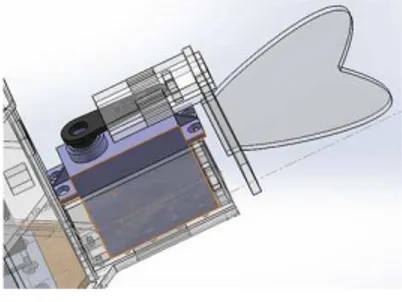
Caudal fin of the robotic fish is made from acrylic sheets. Its parts are assembled into a joint which is attached to the waterproof servo motor. The joint has been designed to imitate the movement of a fish vertebral column. In the starting stage, servo arm position is set to 90 degrees as shown in Fig. 7. When the robot is operated, the caudal fin performs a sine wave by rotating back and forth smoothly within an amplitude An. This action provides a similar effect
as the extensibility and contractility of muscle in a fish. The caudal fin is a heart-shaped acrylic sheet with an arc line to reduce lateral force acting on the robot. A surface area of the caudal fin is enough to push surrounding water.
Fig. 7. Caudal fin of the robotic fish
A position of the caudal fin is controlled automatically by a microcontroller. Infrared sensors of the robot are used in obstacle detection and send signal to a microcontroller. To avoid collisions, swimming direction is subject to change by the sensor signal. The microcontroller executes a program embedded equation (1) and (2) inside. The equations must have parameter values to calculate propelling amplitude An.
The parameters are sent from a graphical user interface (GUI) via serial communication.
C. Orientation Mechanism
Orientation mechanism is located at the bottom of the robotic fish. This location is suitable for prevention of instability. The instability occurs when the center of gravity and the center of buoyancy are not vertical aligned. A cylinder steel weight is attached on a servo arm. Employing in-line pattern, servo motors are established on square-shaped holes as shown in Fig. 8. MEMS motion sensor is installed to measure the tilt angles.
Fig. 8. Orientation mechanism inside the robotic fish and rotating areas
Servo arm positions can be adjusted on GUI. During the starting stage, servo arm positions are set to 90 degrees. A sum vector of all moments is equal to zero. So the robotic fish floats horizontally. To orient the robotic fish in the water, four servo arms are rotated to different positions. The resultant of all moments makes the center of gravity shifted. Heading of the robot depends on the rotation patterns as shown in Table II. The patterns are set by the directions of the sum vector. A reference plane is X-Y plane which depends on the installation of MEMS motion sensor. S1 to S4 are the names of servo motor used in the orientation mechanism as shown in Fig. 8. The system has been designed to cover all the positions and orientations of all degrees in the working space of the robot. It is able to fine-tune angle and position in a small degree that reflects the position and the heading of the robot. Tilt angles of the system can monitor on GUI software.
TABLEII
ROTATION PATTERNS OF SERVO ARMS
The Robot Heading in X-Y Plane
Servo Arm Position (Degrees)
S1 S2 S3 S4 0, Y 90 0 90 180
X, Y 45 0 180 135 X, 0 0 180 180 90 X, -Y 0 180 135 45 0, -Y 90 180 90 0 -X, -Y 180 135 45 0 -X, 0 180 90 0 180 -X, Y 135 45 0 180
D. Control Software
Control software has two parts, an on-board system and a user GUI. They transfer data and command via serial communication. A communication protocol is designed to send data packets from the GUI to the microcontroller which received infrared sensor signal and calculating the propelling amplitude An. The received data has been
translated into parameter values and orientation patterns. Moreover, the microcontroller also sends the measuring data from MEMs motion sensor to a computer for monitoring. The GUI includes orientation control section, movement control section and monitoring data section as shown in Fig. 9.
Fig. 9. Graphical User Interface (GUI) for sending and monitoring data
V. EXPERIMENT
A. Experimental Environment
The dimension of robot body is 200 mm in length and width, and 150 mm in height. Every joint of construction has been sealed with silicone sealant to prevent the leakage. The iron cylinder weight, which has been attached on servo arm, is 59.8 g. The inside of the robot has been installed a foam sheet and MEMS motion sensor to buoy the robot up and measure angle values, respectively. The sensor has been installed at the center of a foam sheet because this position is the pivot point of the system. The robot body floats in a large basin while electrical components, as well as battery, microcontroller and electrical wires, have been connected outside the basin. Thus, the electrical wires cause a disturbance to the robot body. An error occurring in the system can be neglected because tilt angle can be compensated by the average value at the starting position.
Experimental results are presented in graphs with mathematical equations. The relations between tilt angle and servo arm position can be estimated by linear equation and polynomial equation. The mathematical equation is the characteristic of the established pattern using for calculation of servo arm positions from desired tilt angles.
B. The Relation between Tilt Angle and a Servo Motor For a servo motor, reference frame and experimental platform are shown in Fig. 1. The platform size has been reduced to suit an operating area. Servo arm rotates from 0
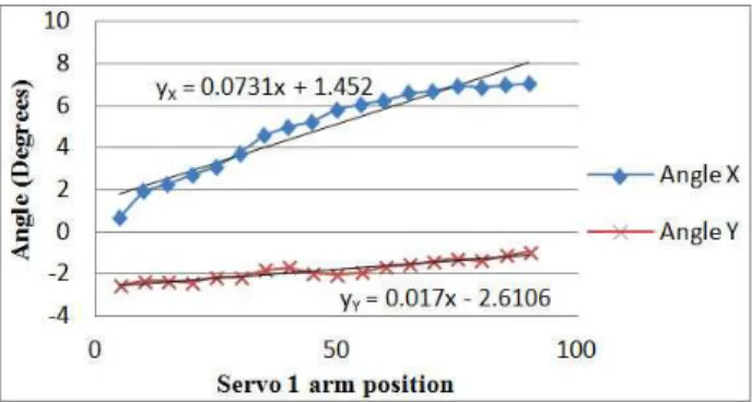
to 180 degrees. Its position is adjusted every 5 degrees to collect the experimental data. The experimental result presents the relation between tilt angle in X-Z and Y-Z plane, and servo arm position as shown in Fig. 10.
Fig. 10. The characteristic of a servo motor between servo arm position and tilt angle
In the starting stage, servo arm position is set to 90 degrees. Tilt angles of X-Z and Y-Z plane are both closer to 0 degrees. An experimental result implied that a servo motor cannot make the robot body float horizontally. To find the characteristic of this pattern, linear and polynomial equation is used for estimating the trendlines of angle θ in X-Z plane (Angle X) and angle β in Y-Z plane (Angle Y), respectively. The characteristic of angle β is a polynomial equation because the servo arm rotates about the X-axis. Thus, the robot body is rotated about the X-axis also. The results show that a servo motor has an effect only on a single axis but does not cover the working sphere.
C. The Relation between Tilt Angle and Servo Motors --Parallel pattern, servo motors have been established with a reference axis as shown in Fig. 3. To collect the experimental data, servo arms are rotated apart every 5 degrees. The experimental results are shown in Fig. 11 and 12. Two separate graphs are shown servo arm position of servo motor S1 and S2, respectively. From the two graphs, the angle θ of X-Z plane (Angle Y) do slightly change. This change has no effect on the system. The angle β of Y-Z plane (Angle X) has the maximum tilt angle when both servo arms are parallel. The characteristic of the pattern employs linear equation to estimate the trendlines. The mathematical equations can be used for calculating servo arm position from a desired tilt angle.
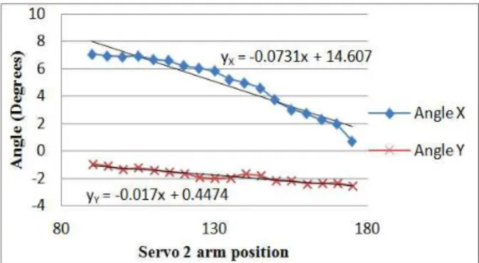
Fig. 12. The characteristic of parallel pattern between Servo 2 arm position and tilt angle
--In-line pattern, servo motors have been established with a reference axis as shown in Fig. 4. The experimental results are shown in Fig. 13 and 14. From the two graphs, the tilt angle β of Y-Z plane (Angle X) increases to the maximum position. In the X-Z plane (Angle Y), the average values of angle θ is about zero. The experimental results show that the robot body rotates about X-axis only. However, in-line pattern has flexibility to be used with the orientation mechanism. The characteristic employs linear equation to estimate the trendlines. The mathematical equations can be used for calculating servo arm position from a desired tilt angle.
Fig. 13. The characteristic of in-line pattern between Servo 1 arm position and tilt angle
Fig. 14. The characteristic of in-line pattern between Servo 2 arm position and tilt angle
VI. CONCLUSION
The orientation mechanism of this fish robot employs the servo motor position pattern. The orientation mechanism uses two sets of in-line pattern to establish perpendicularly.
The desired tilt angle happens when all servo motors are controlled by the mathematical equations. Weight and platform size directly affect the orientation because it depends on the moment and buoyancy. The number of servo motors in the robot body reduces a limit of the robot orientation. Actually, servo motors can establish in various patterns. Any established pattern depends on a usage and a limit of a hardware design. The aim of this paper is to become a background in developing orientation mechanism area. It provides the mathematical equation to describe the robot orientation appearing in the system. Future works are about finding a general equation to describe the characteristics of servo pattern and the relation between weight and platform shape.
REFERENCES
[1] J. Gray, “The propulsive powers of the dolphin,” Journal of Experimental Biology, pp. 192-199, August 1935.
[2] C.M. Breder, “The locomotion of fishes,” Zoologica, vol. 4, pp. 159-256, 1926.
[3] P. Nilas, “A Prototypical Multi-Locomotive Robotic Fish Parametric Research and Design,” Proceedings of the World Congress on Engineering and Computer Science 2011, vol. 1, USA, pp. 343-348, 2011.
[4] Le Minh Thuan, Nguyen Truong Thinh, Nguyen Ngoc Phuong, "Study of Artificial Fish Bladder System for Robot Fish," Proceedings of the 2011 IEEE International Conference on Robotics and Biomimetics, Thailand, pp. 2126-2130, December 2011.
[5] Ahn, S.-S. and Lee, Y.-J., Novel Spherical Robot with Hybrid Pendulum Driving Mechanism, Adv. Mech. Eng., vol. 2014, 456727, pp. 14, 2014
[6] D. M. Lane, M. Sfakiotakis, and B. J. Davies, “Review of Fish Swimming Mode for Aquatic Locomotion,” IEEE Journal of Oceanic Engineering, vol. 24, no. 2, April 1999.
[7] Buoyancy, Stability, and Ballast 2. Cornerstone Electronics Technology and Robotics III.
[8] M. J. Lighthill, “Note of swimming of a slender fish,” Journal of Fluid Mechanics, vol. 9, pp. 305-317, 1960.
[9] N. Kato and T. Inaba, “Guidance and Control of Fish Robot withApparatus of Pectoral Fin Motion,” Proceedings of the 1998 IEEE International Conference on Robotics & Automation Leuven, Belgium, pp. 446-451, May 1998.