Brazilian Microwave and Optoelectronics Society-SBMO received 07 May 2018; for review 23 May 2018; accepted 24 Aug 2018 Brazilian Society of Electromagnetism-SBMag © 2012 SBMO/SBMag ISSN 2179-1074
Abstract—Ground Penetrating Radar is a complex nondestructive
evaluation technique where the antenna is the most critical part. The antenna is responsible for transmission and reception of waves at the proper level and frequencies defined in the GPR system specifications. Important GPR features such as resolution and penetration depth depend on its characteristics. In this context, this work outlines the fundamental GPR system theory in order to discuss procedures for improving antennas to GPR applications. Additionally, recent works regarding GPR antenna optimization are reviewed and placed in the context of a framework for GPR antenna design and optimization.
Index Terms—GPR Antenna, design, optimization.
I. INTRODUCTION
Nondestructive evaluation (NDE) is the process of inspecting, testing, or evaluating materials,
components or assemblies for discontinuities, or variations in characteristics without affecting the
serviceability of the system itself. In 2017, many nondestructive testing (NDT) societies signed a
cooperation agreement to regulate their actions [1]. The ASTM D6432-11 has as scope the
standardization for using the surface ground penetrating radar method for subsurface investigation [2].
Ground-penetrating radar (GPR) is a nondestructive inspection tool that uses electromagnetic (EM)
fields to image the subsurface [3][4]. The technique is based on emitting EM waves into a solid to assess
its condition. Usually a waveform with wide frequency content is designed for this aim. The application of
EM waves to inspect the underground brings advantages and difficulties for the user. The electrodynamics
of the process can be summarized as follows: when the EM wave encounters a hidden body or a boundary
having different electrical characteristics part of its energy is reflected and part of it is refracted. The
resulting waves travel with different velocities and possess information on the target characteristics.
Imaging is achieved through data processing of the wave launched at and the wave reflected from
the structure under test. The main issue in using GPR is to relate the received EM field to its true
spatial location. If the physical process is well interpreted, GPR can be used to detect subsurface
objects, changes in material properties, voids and cracks.
GPR has many applications in different types of materials. Recent studies can be outlined as:
archeology, desert soil inspection, lossy dielectrics, boundary layer detection, airborne GPR,
A Review of Ground Penetrating Radar
Antenna Design and Optimization
X. L. Travassos1, S. L. Avila2, R. L. da S. Adriano3, N. Ida4
1UFSC, Campus Joinville, Rua Dona Francisca, 8300 – CEP 89219-600, [email protected] 2IFSC, Campus Florianópolis, Av. Mauro Ramos, 950 – CEP88020-300, [email protected]
3UFMG, Campus Pampulha, Av. Antônio Carlos 6627 – CEP 31270-901, [email protected] 4
Brazilian Microwave and Optoelectronics Society-SBMO received 07 May 2018; for review 23 May 2018; accepted 24 Aug 2018 Brazilian Society of Electromagnetism-SBMag © 2012 SBMO/SBMag ISSN 2179-1074 diffraction tomography, excavation, landmine detection, forensic surveys, real time inspection of
pavements from moving vehicles, high-conductivity surfaces, directional borehole, layered
vegetation, wood and forest litter, the applications are endless. As an example, Fig. 1 describes a GPR
assessment of concrete conditions where the goal is to locate reinforcement bars. Manufacturers have
been developing new systems for a variety of applications. Benchmarking of commercial GPR
systems is discussed in [5] and [6]. It includes information on GPR manufacturers and their products,
field tests and data analysis.
Fig.1. GPR assessment of concrete condition.
The unique advantages offered by GPR are related to the overall performance achieved by
electromagnetics at radio and microwaves frequencies. With reasonable power requirements, they
combine a reasonably large penetrating range (more than optical and infrared sensors but less than
acoustic and seismic methods) with sufficient spatial resolution (greater than acoustic and seismic but
lower than infrared and optical techniques) and a fair contrast between host and target media. But the
ability to detect a broad range of targets also presents drawbacks, because inhomogeneous soils or
additional scattering from non-target objects (known as clutters) interact with the scattered field of the
actual target, masking the detecting pulse.
The main GPR limitations [3][4] and some recent studies about them are:
i. For some GPR applications the medium behaves approximately linearly. Examples of materials that affect target detection are high-conductivity materials or heterogeneous conditions i.e. in
lossy dielectrics [7], layered vegetation [8], desert soils [9], seawater [10], and forest litter [11] the behavior is nonlinear;
ii. Relatively high energy and time consumption can be problematic for wide field surveys [12]-[16];
iii. The lateral survey resolution is based on prior information of targets and the material under test that need to be identified. This information is used to define the spatial sampling of the survey
for B or C-scans [17]-[21];
iv. Refocus radargram to the true space location of medium boundaries as observed in [8], [14] and [22]-[24];
Brazilian Microwave and Optoelectronics Society-SBMO received 07 May 2018; for review 23 May 2018; accepted 24 Aug 2018 Brazilian Society of Electromagnetism-SBMag © 2012 SBMO/SBMag ISSN 2179-1074
capability according to [8] and [24]-[27].
There are several issues that can be improved in a GPR system to overcome the limitations
described. The aim of this paper is to describe the most relevant GPR features for an NDT assessment,
and some of the techniques to improve the performance of the principal device in a GPR system: the
antenna. The organization of the paper is as follows. Section II provides an overview of the GPR
scenario, main characteristics of commercial GPR and applications, and discusses relevant
information for the design of any survey. Section III explains the parameters needed for a successful
GPR antenna design. Section IV proposes a framework for GPR antenna design and optimization.
II. THE ANTENNA IN THE GPRSYSTEM
As stated before, GPR has limitations concerning complex geometries and electrical properties. To
improve the technique several developments are continually being investigated considering different
applications. These developments are reflected in published research and in award of patents. A
selection of recent patents relevant to GPR is: a method of GPR concrete road construction cushion
thickness quick detection [28]; method for detecting irregular aggregate permittivity [29]; systems and
methods for detecting soil characteristics [30]; methods for forming 3D image data and associated
apparatuses [31]; method of grouting compaction identification of prestressed concrete beams [32].
Different GPR applications and the main GPR limitations cited demand different types of antennas.
There are several types of antennas used in GPR. For instance, some applications demand a high
depth penetration with low resolution while other applications require opposite characteristics. High
resolution applications require antennas with higher bandwidths which in turn results in low
penetration depth of inspection.
The tradeoff between resolution and depth of penetration is defined when the antenna central
frequency is chosen. On the other hand, target identification usually imposes much more strict
requirements on antennas in comparison with a system for merely target detection. It is important to
notice that the antenna is a system in itself with its own transfer function that can be
frequency-dependent with a non-linear phase response that can be critical for an impulse GPR system. Since the
main objective of GPR systems is the generation of an image, phase distortion is a serious problem.
On the other hand, in frequency modulated or synthesized GPR, the requirement for linear phase
response from the antenna can be relaxed. This allows the use of certain types of antennas with
complex frequency response, as their effect can be corrected by system calibration if necessary.
Considering the foregoing, important aspects of GPR antenna design are:
i. The antenna should have a wide frequency bandwidth for better resolution. The maximum depth of
investigation decreases when the electromagnetic wave frequency increases. In reality, most
sub-surface radar systems operate at frequencies below 5 GHz, as the examples in Tables I and II show;
ii. The antenna should have well-behaved and consistent performance across the antenna’s operational
Brazilian Microwave and Optoelectronics Society-SBMO received 07 May 2018; for review 23 May 2018; accepted 24 Aug 2018 Brazilian Society of Electromagnetism-SBMag © 2012 SBMO/SBMag ISSN 2179-1074
dispersion. High gain and narrow beamwidth are fundamental to resolve close proximity targets.
Most applications require the antenna to be small in size and low in weight. For energy
consumption purposes, the antenna length is related to its central frequency [33]. Compact and rugged
physical characteristics are especially important for mounting the system in confined spaces.
Those antenna characteristics are highly related to the GPR system specification. In order to
illustrate the variety of possibilities, Tables I and II show some applications and types of GPR systems
considering the waveform and the coupling to the structure under test.
TABLE I.APPLICATIONS USING TIME-DOMAIN WAVEFORM
Ref. Application Media
Antenna Type
Coupling (Air/Ground)
Bandwidth [GHz]
Ringing concerns
[11] forest litter horn A 0.8 to 5.2 no
[13] pavement inspection half-elipse A 0.25 to 0.75 yes
[14] landmine detection bowtie A 1.5 yes
[24] forensic survey horn A 0.27 to 0.9 MHz no
[34] boundary layer detection loaded dipole G 0.25 to 0.75 yes [35] metallic target behind concrete wall horn and vivaldi A 1.5 to 4.5 no
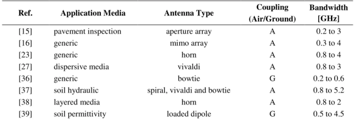
TABLE II.APPLICATIONS USING FREQUENCY-DOMAIN WAVEFORMS
Ref. Application Media Antenna Type Coupling (Air/Ground)
Bandwidth [GHz]
[15] pavement inspection aperture array A 0.2 to 3
[16] generic mimo array A 0.3 to 4
[23] generic horn A 0.8 to 4
[27] dispersive media vivaldi A 0.8 to 3
[36] generic bowtie G 0.2 to 0.6
[37] soil hydraulic spiral, vivaldi and bowtie A 0.8 to 5.2
[38] layered media horn A 0.8 to 2
[39] soil permittivity loaded dipole G 0.5 to 4.5
Table I presents recent works for different GPR applications for time-domain systems. Time-domain
systems are basically characterized by sending a pulse or impulsive waveform to the structure under test.
This type of waveform has a short period of time and a large bandwidth. As can be seen in Table I, it is
possible to use various types of antenna with this waveform. However, some types of antennas present
some drawbacks when considering time-domain waveforms or the coupling to the structure under test.
Planar bowtie and dipole antennas can cause late-time ringing when used for transmitting a short time
pulse. Late-time ringing can blur target information in a GPR assessment. In addition, these antennas
can exhibit coupling problems when used on irregular surfaces. For those applications, horn antennas
are more appropriate since they can be located at some height from the structure under test.
Most of the commercial GPR systems use time-domain waveforms. However, there are developments
and ongoing research into frequency-domain options. The later have some advantages over time-domain
systems since they require less energy and provide more information about the target characteristics.
Brazilian Microwave and Optoelectronics Society-SBMO received 07 May 2018; for review 23 May 2018; accepted 24 Aug 2018 Brazilian Society of Electromagnetism-SBMag © 2012 SBMO/SBMag ISSN 2179-1074 GPR system. According to Table II frequency-domain GPR systems can be used for a variety of
applications. Some applications may require better images. One important characteristic of images is the
phase-dependent feature. To improve GPR images antenna arrays can be used to minimize phase
problems. In addition, air or ground-coupled options can be used for different depth or resolution
specifications.
When it comes to commercial options, time-domain systems are prevalent as shown the Table III.
This is due to the fact that frequency-domain systems are relatively new compared to the time-domain
option. However, since the electronics of frequency-domain systems are less expensive than the
time-domain option there is a growing offering of this system in the market.
TABLE III.SOME COMMERCIAL GPRSYSTEMS.
Manufacturer Waveform Antenna Type Coupling (A/G)
Ditch Witch Impulse dipole G
Easyrad Impulse dipole A, G
Geoscanners Impulse bowtie, airbone and borehole A, G
Logis-Geotech Impulse horn A, G
GSSI Impulse horn and shielded array A, G
IDS GeoRadar Impulse horn and shielded array A, G
Mala Geoscience Impulse Dipole G
TerraPlus Impulse, CW bowtie and borehole G
Advantages and disadvantages of the different waveforms for GPR are also dependent on
operational requirements of the final system, including weight and size, power consumption,
complexity and off the shelf availability of the hardware, and therefore its cost. Spectral regulations
can also play a role in choosing the operational frequency and bandwidth, with effects on the
achievable resolution and depth of penetration, as well as on the design of the antennas.
Another important feature is the coupling compromise: the antenna input impedance is directly
affected by the distance between the antenna and the structure under test. Ground-coupled GPR can
couple more energy into the ground and extract more energy out of it, which results in clearer data
and greater depth of investigation. In addition, surface coupling and antenna ringing represent
problems, which complicate the collection of information without proper signal processing. The next
section discusses some important GPR system parameters.
III. GPRSYSTEM DESIGN PARAMETERS
GPR systems manufacturers offer several configurations according to their system components. The
system configuration directly affects the performance of the NDT assessment. In numerous
applications, prior information about the structure under test and the target characteristics are known.
Considering this, the system specification plays a major role in the success of the assessment. In order
Brazilian Microwave and Optoelectronics Society-SBMO received 07 May 2018; for review 23 May 2018; accepted 24 Aug 2018 Brazilian Society of Electromagnetism-SBMag © 2012 SBMO/SBMag ISSN 2179-1074
A. Waveform
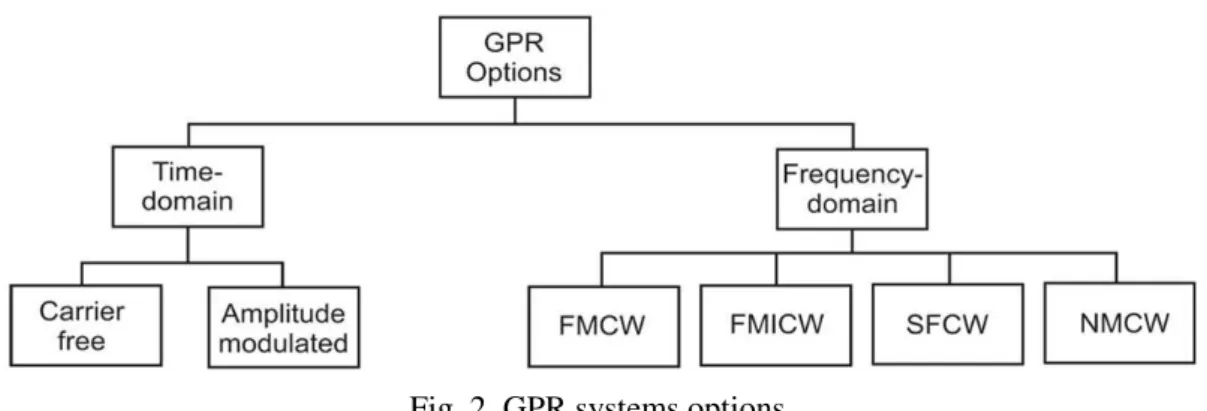
Most of the GPR equipment is based on two categories: time or frequency-domain options. Fig. 2
shows the most relevant options considering these categories. GPR systems that shape a time-limited
waveform considering changes in its amplitude are known as impulse GPR. Continuous wave (CW)
GPR are based on band-limited signals. This type of GPR transmits a signal of infinite duration, as a
continuous sine wave, and receives it simultaneously. In this configuration, it is possible to detect buried
targets but it not possible to resolve range since the signals do not change. To improve detection the
signal bandwidth should be widened. This can be done by using some sort of modulation.
For instance, in amplitude modulation the continuous wave can be modified with amplitudes 1 and
0 at different times during the inspection. This is called pulsed GPR. Since the transmission and
reception times are well defined it is possible to associate then with the target range. However, when
dealing with GPR and its applications it is desirable to have control of the power spectral density and
in turn the resolution of the assessment.
Another approach to do this is adding more frequencies by increasing or decreasing the oscillation
in the waveform. This configuration is called frequency-modulated continuous wave (FMCW) [40].
Instead of using transmitted and received times of pulses FMCW uses the difference in frequency.
This type of GPR system suffers from interference issues.
Fig. 2. GPR systems options.
A different method can be employed to both CW or pulsed GPR where the transmitted frequency of
tones or pulses shifts in a given interval or steps across a defined bandwidth. In this way, the signal
spectrum is finite and not continuous. This technique is called stepped frequency continuous wave
(SFCW)[41]. The frequency step avoids phase ambiguity by measuring the phase difference between
returned signals at each frequency. In addition, the hardware associated with SFCW is simpler than
that employed in FMCW. A variation of the SFCW technique involves gating the timing of the
transmitter and receiver circuits.
A comparison between impulse and CW GPR can be found in [42]-[44]. The impulsive system is still
prevalent over the CW option. However, the development of digital signal-processing technology,
resulting in cheaper, faster and more accurate equipment, as well the development of inverse algorithms
Brazilian Microwave and Optoelectronics Society-SBMO received 07 May 2018; for review 23 May 2018; accepted 24 Aug 2018 Brazilian Society of Electromagnetism-SBMag © 2012 SBMO/SBMag ISSN 2179-1074 As mentioned above, advantages and disadvantages of different waveforms for GPR are also
dependent on operational requirements. One of the challenges when using impulse waveforms is that of
producing a pulse short enough to achieve the desired bandwidth, i.e. with suitable fast rise and fall
times. The antenna should be designed to avoid ringing effects or distortion of the pulse shape. Another
challenge arises if the received pulses are sampled in real time in the analogue-to-digital converter
(ADC), since the ADC must operate at high enough frequencies to digitize correctly the waveforms. A
common problem for active radar systems for CW is the strong backscattered signal from the air-ground
interface. This undesired signal can overshadow the reflections from actual targets, especially those with
low radar cross section such as human beings, and limit the dynamic range of the receiver, which could
be saturated and blocked. Although techniques have been developed to address this problem including
the frequency modulated interrupted continuous wave (FMICW) or the noise modulated continuous
wave (NMCW) waveforms, which can be used as an alternative technique or combined with the existing
ones. FMICW signals have additional effects over normal FMCW, namely range-dependent received
power according to the mean received signal of the gating sequence, presence of “blind ranges”, risk of
aliasing, and overall reduction of the received power [43].
B. System Bandwidth
Bandwidth describes the range of frequencies over which the antenna can maintain desirable
parameters with minimal deviation. Regarding GPR systems, the bandwidth is one of the determining
parameters used to decide upon an antenna type. For instance, some antenna types have very narrow
bandwidths and cannot be used to transmit pulses with large frequency content. Bandwidth is
typically quoted in terms of the input impedance. This is due to the reflected waves that are generated
with the change in the antenna impedance which in turn augments the voltage standing wave ratio
(VSWR). VSWR is directly related to the S11 parameter [33].
C. Antenna Position
GPR systems can also be classified by type of coupling to the structure under test as air-launched or
coupled. The antennas can be in contact with the medium in what is referred to as
ground-coupled GPR, or they can be above it in air-ground-coupled GPR. The efficiency of a GPR antenna can be
substantially reduced when it operates close to a dispersive medium because of the demand for more
power. The specification of how close the antenna can operate from the structure under test is another
important issue. The antenna input impedance is directly affected by the distance between the antenna
and the structure under test.
Ground-coupled GPR results in clearer data and greater depth of investigation. However, it needs
proper signal processing due to the coupling to the surface and antenna ringing problems. Air-coupled
GPR on the other hand produces more difficult data to work with, but since the antennas are not in
contact with the ground, data can be collected at a much higher speed without damaging the antennas.
Brazilian Microwave and Optoelectronics Society-SBMO received 07 May 2018; for review 23 May 2018; accepted 24 Aug 2018 Brazilian Society of Electromagnetism-SBMag © 2012 SBMO/SBMag ISSN 2179-1074 For air-coupled applications, horn antenna has an advantage over other types because of its narrow
beamwidth, which facilitates a higher gain over a wider frequency range. A comparison between
air-launched and ground-coupled systems can be found in [46] and [47].
D. Antenna Polarization
Polarization mismatch occurs when the radiated field is distorted when propagating in the medium
under test. This distortion depends on electric characteristics of the medium such as heterogeneity and
anisotropy [33]. Some commercial GPR systems use linear polarized antennas. Because of this the
survey is susceptible to the target orientation relative to antennas. If the target has a transverse
orientation relative to the antenna, it may not be detected. To improve the assessment cross-polarized
antennas have been used in order to solve orientation issues. In this configuration the transmitting
antenna radiates two patterns that are orthogonal to each other. By using cross-polarized antennas it is
possible to detect simultaneously the target reflection in two orthogonal polarizations.
E. Ringing Effect Distortion for Impulsive Systems
Different types of antennas are in use for GPR systems. The resistively loaded dipole is simple, easy
to design and possess linear polarization. However, it has a major disadvantage of poor gain. This makes
other planar antennas, such as bow-tie and frequency-independent structures, a more attractive choice.
These two are mainly used in impulse GPR applications because of their non-dispersive characteristics
and their relatively high gain. Nevertheless, both suffer from significant impedance mismatch at the feed
point when used for air coupled GPR applications [46][47]. In addition, there is the ringing effect
distorting in the time-domain waveform [33]. Resistive loading is usually used to overcome this
drawback but this technique leads to deteriorating gain performance over the frequency band [34]. Horn
antennas have narrow beamwidth that naturally guarantee a higher directivity gain over a wider
frequency range. The main design challenge of horn antennas is to achieve an impedance match in order
to minimize feed point and aperture reflections. All of these antennas have potential to be used in GPR
systems.
F. Pulse Fidelity
Pulse length is not the only signal trait that must be maintained by the antenna, and cannot be used
as the sole metric for determining antenna performance. Pulse shape can also have an effect upon
radar performance. Therefore an additional metric must be used to evaluate radar antennas, known as
pulse fidelity F [48]. Mathematically, pulse fidelity F is the maximum cross-correlation between the
normalized output pulse a(t) and the reference input pulse r(t). The value of F is maximally equal to 1
when the input and output pulses are identical in shape. A parameter τ is used to time sweep r(t)
during optimization of F, eliminating the effect of non-zero time delay between waveforms. Pulse
Brazilian Microwave and Optoelectronics Society-SBMO received 07 May 2018; for review 23 May 2018; accepted 24 Aug 2018 Brazilian Society of Electromagnetism-SBMag © 2012 SBMO/SBMag ISSN 2179-1074
G. Group Delay
Any single-frequency signal passing through a radiating antenna will experience a time delay as a
function of frequency called group delay. Group delay is the negative derivative of phase with respect
to frequency, typically obtained from the crosstalk between the transmitting and receiving antennas
(S12 parameter) in an appropriated test setup environment [49]. A constant group delay versus
frequency leads to a constant propagation time delay and an undistorted output signal. The radar
software evaluates the time delay of the return pulse, corrects for the known antenna group delay, and
determines a single value of distance, the antenna to target round-trip distance. A variable group delay
versus frequency causes a frequency dependent variation in time delay. Consider an ultra-wideband
frequency range from f1 to f2. Evaluating at f1 and f2 returns the distances d1 and d2. Larger group
delay variations between f1 and f2 lead to larger apparent discrepancy when determining the range to
target, between d1 and d2. Therefore, radar distance resolution is directly influenced by antenna group
delay performance. The relationship between group delay and radar resolution can also be seen by
analyzing the effect of a variable group delay on radiated pulse length. Impulse trains are produced at
the receiving antenna when a radiated pulse reflects off of closely spaced objects. Non-dispersed
pulses are easily resolved as their amplitude decreases to zero before the subsequent pulses arrive.
However, dispersed pulses can be wider than the time differences between returns, causing adjacent
pulse overlap. This overlap prevents the radar software from distinguishing between returns from
closely spaced objects, decreasing system spatial resolution.
As well as the ringing effect distortion or pulse fidelity, the group delay obtained from the S21
parameter focus on the pulse-preserving capabilities of the received signal. This leads to some
restrictions regarding the antenna design. Any antenna used in a GPR system must be designed to
minimize group delay variations over the radiating bandwidth. However, for successful evaluation of
the S21 parameter, the environment in which GPR devices are expected to operate needed to be proper
modeled. This can be quite challenging for multipurpose GPR systems. An alternative approach is to
obtain the group delay from the normalized far-zone electric field for a single antenna [50]. Using the
information from the far-field group delay and antenna gain it is possible to analyze the
pulse-preserving capabilities of the antenna without considering the GPR environment.
H. Antenna Types
Based on what has been presented, the properties of the GPR system and the application requirements
will dictate which antenna features need to be adjusted for better performance. Technical and
methodological aspects concerning the design of antennas for GPR applications are discussed in
[51]-[53]. These studies compare bow-tie antennas, Vivaldi antennas, horn antennas, loaded dipole antennas,
spiral antennas and tapered slot antennas based on antenna features. For example: if the antenna
designed is intended for a GPR system mounted on the front of a vehicle the system uses a linear array
ground-Brazilian Microwave and Optoelectronics Society-SBMO received 07 May 2018; for review 23 May 2018; accepted 24 Aug 2018 Brazilian Society of Electromagnetism-SBMag © 2012 SBMO/SBMag ISSN 2179-1074 penetration imaging to detect buried objects. From an antenna design perspective, these devices can be
almost any shape and size. In order to ensure strong radar returns from potentially narrow objects with
unknown orientations antenna polarization must be considered. For instance, an x-oriented linearly
polarized antenna could miss objects with small x-directional cross-sections relative to the wavelength.
The current optimum UWB antenna choice for impulse radar applications is the hexagonal horn with
abrupt radiator. This UWB horn design usually operates from 0.27 MHz to above 12 GHz. It has
inherently constant group delay versus frequency due to the abrupt radiator design, which causes all
frequencies to radiate from the same location on the launcher plate. It also has very low cross-coupling
due to the horn structure. However, this antenna design is linearly polarized and has manufacturing
issues that limit its potential in portable radar applications. Each horn must be soldered and manually
tuned due to the complicated geometry of the launcher plate inset within the horn wall. This raises costs
while reducing repeatability and consistency between antennas. An alternative for the horn antenna to
limit size and cost is required. It must also be circularly polarized. In the short list of antenna types that
are simultaneously UWB, circularly polarized, and machine-fabricable in a micro-strip environment,
spiral antennas are a particularly valuable choice due to their frequency-independent (FI) properties.
According to [54], there is a class of antennas whose pattern and impedance are practically independent
of frequency for all frequencies above a minimum cutoff value. The key significance of frequency
independence on spiral antennas is that a change in frequency only rotates the active region, the
radiating area, along the spiral arms. As long as the arm length is sufficient, any frequency can
effectively radiate. Therefore the scaling factor determines the spiral arm length and consequently the
antenna’s lower cutoff frequency, allowing for FI antennas to be scaled in size according to the desired
frequency response. By choosing a scaling factor large enough to achieve desired electrical performance
but small enough to improve upon the hexagonal horn size, it should be possible to create a design that
rivals or exceeds the performance of existing designs at a lower cost. The primary issue preventing
frequency independent antennas from use in GPR systems is pulse dispersion. Because the active region
moves as a function of frequency, FI antennas radiate dispersed signals [55].
I. Regulation and Standards
In order to design a GPR antenna, it is important to comply with regulation and standards. IEEE
Standard Definitions of Terms for Antennas [56] establishes definitions for antennas and for systems
that incorporate an antenna as a component of the system. The antenna requirements for GPR systems
is defined by USA Code of Federal Regulations: technical requirements for ground penetrating radars
and wall imaging systems [57]; and technical requirements applicable to all ultra-wide band (UWB)
devices [58]. Among other specifications, FCC restricts the GPR operation to frequencies below 10.6
GHz. Other restrictions concern electromagnetic compatibility: particular attentions to the effective
(or equivalent) isotropic radiated power (EIRP) limits per bandwidth, for example for 960 MHz to
Brazilian Microwave and Optoelectronics Society-SBMO received 07 May 2018; for review 23 May 2018; accepted 24 Aug 2018 Brazilian Society of Electromagnetism-SBMag © 2012 SBMO/SBMag ISSN 2179-1074 The concepts and discussions presented in sections I – the GPR application, II – the antenna in the
GPR system and III – GPR system design parameters make possible discuss a framework for GPR
antenna design and optimization.
IV. FRAMEWORK FOR GPRANTENNA DESIGN AND OPTIMIZATION
To improve the GPR system response, a given antenna topology can be reshaped or modified using a
general optimization framework as depicted in Fig 3. The electromagnetic model, the reference antenna
topology or the optimization tool can be chosen according to the GPR system requirements as follows.
Fig. 3. Generalized antenna optimization process. Adapted from Fig. 1 in [59].
A. Electromagnetic Model
Real world problems impose a complex task in the modeling of the GPR assessment. Several issues
contribute to this. The most important are: the inhomogeneous material electric properties (dispersive
lossy dielectrics, non-linear or anisotropic materials); complex geometry (irregular surface and
subsurface, complex antennas and buried targets in several cases must be represented in 3D); and
time-dependent analysis. In this context, numerical modeling is required in order to solve Maxwell’s
equations in complex and realistic GPR application.
For the electromagnetic computational analysis of the antennas and the entire GPR surveys, most
publications use the finite-difference time-domain method (FDTD) [60][61]. FDTD can cover a wide
frequency range and treat nonlinear material properties, which make it suitable for GPR applications.
The use of libraries is also becoming commonplace by its easy. EM fields simulation has several
examples of source tools. For instance, there is the GPRmax community. GPRmax is an
open-source software that simulates GPR applications using FDTD numerical method written in Python
Brazilian Microwave and Optoelectronics Society-SBMO received 07 May 2018; for review 23 May 2018; accepted 24 Aug 2018 Brazilian Society of Electromagnetism-SBMag © 2012 SBMO/SBMag ISSN 2179-1074 simulation software package to model electromagnetic systems [63].
State-of-the art of commercial software point to multiphysics couplings, such as EM heating,
temperature dependent material properties, EM field dependent material properties and strain and
stress dependent material properties and deformed geometry. Examples of commercial software are
ANSYS HFSS [64], Altair FEKO [65], CST Microwave Studio [66] and GSSI RADAN [67]. We did
a survey with more than 80 commercial software that have been used to GPR applications. The most
representative commercial methods are FDTD (~35%).
B. GPR Antenna Optimization Goals
If the goal is to design an optimized antenna, the features for the use of this device must be
addressed. The system properties also should be considered. These properties impose restrictions on
antenna type and design. Table IV summarize some recent approaches in the design of GPR antennas.
It is highlighted here the objectives chosen, the adjusted parameters and the optimization methods
used. The majority of studies look for an antenna geometry that meets certain performance
specifications, not the entire GPR application.
Considering all aspects explored in section I, II and III as well as the works studied in Table IV, this
work admits that the GPR antenna design is based on three aspects: Low cost: the antenna should be built in a micro-strip structure;
Low profile: the antenna should be planar with the smallest volume possible;
High electromagnetic performance: steady and proper gain, directivity, half power beam
width (HPBW), impedance matching, VSWR (S11), group delay and pulse fidelity.
The group delay variation provides insight into the quantity of pulse dispersion, and the pulse
fidelity quantifies the differences between input and output pulse shape (specific for impulse GPR
systems). Therefore, an antenna’s ability to effectively radiate a short pulse is fully characterized
through return loss, group delay and pulse fidelity testing.
C. Optimization Process
Electromagnetic optimization problems are often computationally expensive, nonlinear and
composed by conflicting goals [60][61]. The GPR antenna design involves simultaneous optimization
of multiple objectives that often are competing. As consequence, there may not exist one solution that
is the best with respect to all objectives. Usually, in a multiobjective optimization problem (MOP) the
aim is to determine the tradeoff surface, which is a set of non dominated solution points, known as
Pareto-optimal (PO) [79][80].
There are several methodologies to perform MOP, each of them having their own advantages and
disadvantages. Analyzing the methods presented in Table IV it may be note that, with exception of
[73], all the papers are based on parametric optimization. In parametric optimization, the antenna
Brazilian Microwave and Optoelectronics Society-SBMO received 07 May 2018; for review 23 May 2018; accepted 24 Aug 2018 Brazilian Society of Electromagnetism-SBMag © 2012 SBMO/SBMag ISSN 2179-1074 has the advantage of preserving the main characteristics of the chosen antenna, for instance,
optimization based on Vivaldi or horn antennas will keep the high gain characteristics of these
antennas. Additionally, previous knowledge about the behavior of the antenna can be very useful to
define an initial guess and the most important parameters. This can reduce the search space during the
optimization process.
TABLE IV.GPRANTENNA OPTIMIZATION OBJECTIVES AND METHODS
Ref. Antenna Type Goals and Methods
[26] dipole To fit into the mass and volume allocation, wire antennas made of identical loaded dipoles have been selected; the resistive profile along the monopoles needs to be chosen to ensure proper behavior of the antenna once they are deployed on the surface. No optimization method has been cited.
[68] bowtie Antenna geometry optimization using a multiobjective genetic algorithm (Non dominated Sorting Genetic Algorithm II), looking for (i) S11 below 10dBi; (ii) maximum gain; and (iii) the width of the band where the gain is between its maximum value and 3dB below it.
[69] eye-shaped slot Antenna geometry is fine-tuned for maximum gain and minimum ringing using exhaustive parametric analyses.
[70] horn Structure anatomy for impedance matching throughout an ultrawide band. The design starts with an analytic model that is optimized using exhaustive parametric analyses.
[71] bowtie The sharp corners are rounded to minimize the end-fire reflections. The design starts with a triangular bowtie antenna. The design is improved with rounding corners and resistive loading introduced using inbuilt optimization tool available in the CST Microwave Studio.
[72] fractal horn The geometry of the patch antenna is changed in order to satisfy the condition of S11 below -10dB. An Ordinary Kriging predictor is used as a surrogate model of the cost function while the Differential Evolution algorithm is used to effectively minimize it.
[73] fractal bowtie To reduce the center operating frequency of the miniaturized antenna, a design strategy is given to determine a reasonable distribution of conductive material within a given domain. A gradient-based topology optimization method has been used.
[74] spiral The geometry of this antenna combined equiangular spiral and Archimedean spiral smoothly looking for a better VSWR performance, axial ratio and gain. The optimization method was not specified.
[75] horn and spiral Optimization of antennas group delay, axial ratio, and pulse fidelity. [76] Vivaldi The antenna dimensions are changed using exhaustive parametric analyses in
order to optimize: the bandwidth, radiation efficiency (S-parameters) and the gain.
[77] horn Reflections and ringing effects are reduced by antenna geometry adjust. [78] wired bowtie VSWR and bandwidth optimization by tapering the arms and applying
Genetic Algorithm to choose the parameters for tapered configuration.
An alternative to parametric optimization is the topology optimization [81][82]. As presented in
[83], topology optimization is a flexible and powerful structure-designing method. It enables the
exploitation of large-scale degrees of freedom (DoFs). As consequence, better performance structures
can usually be expected by topology optimization methods than by the parameterized models with
Brazilian Microwave and Optoelectronics Society-SBMO received 07 May 2018; for review 23 May 2018; accepted 24 Aug 2018 Brazilian Society of Electromagnetism-SBMag © 2012 SBMO/SBMag ISSN 2179-1074 computationally expensive nature of the antenna optimization problem, poses some convergence
issues on the optimization processes. Some good approaches to overcome these problems are
presented in [83]. Another possibility is to use hybrid approaches as presented in [73] where a
topology strategy is used to determine the distribution of conductive material within the antenna while
keeping some bowtie-like structure.
Typically, topology optimization results in high performance nonconventional antennas that fulfill
the goals assigned in the optimization process. However, in most of time, the irradiation mechanism
of the optimized antenna is now well known and sensitivity analysis and robustness test must be
introduced in the optimization process to minimize the influence of the manufacturing uncertainties.
Regarding the optimization methods presented in the references on Table IV, they can be classified
as: exhaustive search [69][70][76][77], deterministic methods [73], and stochastic methods
[68][72][78].
Exhaustive search works well when accumulated experience in design usually implies good starting
points and each parameter can be set independently, However, brute force methods quickly become
inefficient as the number of parameters increase. Although modifying some initial configuration from
a well known antenna can improve its performance, it offers no optimality guarantee.
Deterministic algorithms, on the other hand, enjoy theoretical guarantees on convergence to a local
optimum under certain problem assumptions [84]. They are usually based on a local analysis of the
optimization problem and outperform the other methods when a good start point is available.
Stochastic methods, such as genetic algorithm (GA) [68] and differential evolution (DE) [72], are
very popular, as they require little knowledge about the function properties [84] and can find global
optimum with very high success. They are useful in situations where continuity and differentiability
cannot be assured. Although robust, they are known to be slow, since they require a considerable
amount of function evaluations.
Deterministic and stochastic techniques can also be coupled in hybrid configurations, hybrid
methods try to combine the global search characteristic of stochastic methods with the fast
convergence of the deterministic ones. There are several optimization algorithms, each of them having
their own advantages and disadvantages. The best choice depends on the size of the search space, the
number and behavior of the objective functions and even the familiarity of the designer with the
method chosen, since some methods presents some parameters that can considerably increase the
convergence of the method when well-tuned.
V. CONCLUSIONS
The antenna can be considered as a two-port transducer system characterized by a transfer function
that can be frequency-dependent and may have a non-linear phase response. The performance of this
device is critical for time or frequency-domain GPR systems. The system configuration directly
Brazilian Microwave and Optoelectronics Society-SBMO received 07 May 2018; for review 23 May 2018; accepted 24 Aug 2018 Brazilian Society of Electromagnetism-SBMag © 2012 SBMO/SBMag ISSN 2179-1074 from their antennas.
This work outlined some fundamentals of the GPR system theory in order to translate the GPR
system configuration into antenna requirements. Although different GPR configurations impose
different restrictions on antenna type and design, the procedure to achieve high performance antennas
is consistent and can be described as a generalized optimization problem. This context allowed us to
discuss a framework for GPR antenna design and optimization.
REFERENCES
[1] “Multilateral Recognition Agreement,” International Committee for Non-Destructive Testing (ICNDT), Vienna, Austria, Set. 2017.
[2] ASTM, Standard Guide for Using the Surface Ground Penetrating Radar Method for Subsurface Investigation, D6432, May, 2011, doi: 10.1520/D6432-11.
[3] E. C. Utsi, Ground Penetrating Radar, Theory and Practice, Butterworth-Heinemann, pp. 224, 1st ed., 2017, ISBN: 9780081022160
[4] H. Jol, Ground Penetrating Radar Theory and Applications, Elsevier Science, pp. 509, 1st ed., 2009, ISBN: 9780444533487
[5] P. Maijala and T. Herronen, “Benchmarking of GPR Equipment for Road Surveys,” MaraNord Work Package 3 Report, Oct. 2011.
[6] DIGISOIL, “Final Report Summary –integrated system of data collection technologies for mapping soil properties,” FP7-ENV-2007-1, Community Research and Development Information Service (CORDIS), European Commission, Mar. 2017.
[7] C. Warren and A. Giannopoulos (2016), “Experimental and Modeled Performance of a Ground Penetrating Radar
Antenna in Lossy Dielectric”, IEEE Journal of Selected Topics in Applied Earth Observations and Remote Sensing, v. 9, n. 1, pp. 29-26, doi:10.1109/JSTARS.2015.2430933.
[8] M. Reza M. Ardekani, D. C. Jacques and S. Lambot (2016), “A Layered Vegetation Model for GPR Full-Wave
Inversion”, IEEE Journal of Selected Topics in Applied Earth Observations and Remote Sensing, v. 9, n. 1, pp. 18-29, doi:10.1109/JSTARS.2015.2418093.
[9] R. Q. and L. Liu (2016), “Internal Structure of Sand Dunes in the Badain Jaran Desert Revealed by GPR”, IEEE Journal of Selected Topics in Applied Earth Observations and Remote Sensing, v. 9, n. 1, pp. 159-166, doi:10.1109/JSTARS.2015.2426507.
[10] M. Kirscht, J. Mietzner, B. Bickert, A. Dallinger, J. Hippler, J. Meyer-Hilberg, R. Zahn, and J. Boukamp (2016), “An Airborne Radar Sensor for Maritime and Ground Surveillance and Reconnaissance—Algorithmic Issues and
Exemplary Results”, IEEE Journal of Selected Topics in Applied Earth Observations and Remote Sensing, v. 9, n. 3, pp. 971-979, doi:10.1109/JSTARS.2015.2418173.
[11] F. André, M. Jonard, and S. Lambo (2015), “Non-Invasive Forest Litter Characterization Using Full-Wave Inversion of
Microwave Radar Data”, IEEE Transactions on Geosciences and Remote Sensing, v. 53, n. 2, pp. 828-840, doi:10.1109/TGRS.2014.2328776
[12] F. Sagnard and F. Rejiba (2011) “Wide band Coplanar Waveguide-fed Bowtie Slot Antenna for a Large Range of
Ground Penetrating Radar Applications”, IET Microwaves, Antennas & Propagation, v. 5, n. 6, pp. 734–739 doi: 10.1049/iet-map.2010.0119
[13] X. Li, YicaiJi, W. Lu, and G. Fang (2013), “Analysis of GPR Antenna System Mounted on a Vehicle”, IEEE Antennas and Wireless Propagation Letters, v. 12, pp. 575-578, doi:10.1109/LAWP.2013.2260818
[14] I. Giannakis, A. Giannopoulos and Craig Warren (2016), “A Realistic FDTD Numerical Modeling Framework of
Ground Penetrating Radar for Landmine Detection”, IEEE Journal of Selected Topics in Applied Earth Observations and Remote Sensing, v. 9, n. 1, pp. 37-51, doi:10.1109/JSTARS.2015.2468597
[15] J. De Pue, M. Van Meirvenne and W. M. Cornelis (2016), “Accounting for Surface Refraction in Velocity Semblance Analysis With Air-Coupled GPR”, IEEE Journal of Selected Topics in Applied Earth Observations and Remote Sensing, v. 9, n. 1, pp. 60-73, doi:10.1109/JSTARS.2015.2439333
[16] Z. Zeng, J. Li, L. Huang, X. Feng, and F. Liu (2015), “Improving Target Detection Accuracy Based on
Multipolarization MIMO GPR”, IEEE Transactions on Geosciences and Remote Sensing, v. 53, n. 1, pp. 15-24, doi:10.1109/TGRS.2014.2312937
[17] L. Fu, S. Liu, L. Liu and L. Lei (2014), “Development of an Airborne Ground Penetrating Radar System: Antenna
Design, Laboratory Experiment, and Numerical Simulation” IEEE Journal of Selected Topics in Applied Earth Observations and Remote Sensing, v. 7, n. 3, pp. 761-766, doi:10.1109/JSTARS.2014.2303073
[18] A. Valls, F. García, M. Ramírez, and J. Benlloch (2016), “A Combined Use of GPR Data With Historical Archives for
Brazilian Microwave and Optoelectronics Society-SBMO received 07 May 2018; for review 23 May 2018; accepted 24 Aug 2018 Brazilian Society of Electromagnetism-SBMag © 2012 SBMO/SBMag ISSN 2179-1074 [19] L. Qu, Y. Yin, Y. Sun, and L. Zhang (2015), “Diffraction Tomographic Ground-Penetrating Radar Multibistatic Imaging Algorithm With Compressive Frequency Measurements”,IEEE Geosciences and Remote Sensing Letters, v. 12, n. 10, pp. 2011-2015, doi:10.1109/LGRS.2015.2441991
[20] P. Klesk, A. Godziuk, M. Kapruziak, and B. Olech (2015), “Fast Analysis of C-Scans From Ground Penetrating Radar via 3-D Haar-Like Features With Application to Landmine Detection”, IEEE Transactions on Geosciences and Remote Sensing, v. 53, n. 7, pp. 3996-4005, doi:10.1109/TGRS.2015.2388713
[21] F. Soldovieri, G. Gennarelli, and I. Catapano (2017), “Forward-Looking Radar Imaging: A Comparison of Two Data
Processing Strategies”, IEEE Journal of Selected Topics in Applied Earth Observations and Remote Sensing, v. 10, n. 2, pp. 562-570, doi:10.1109/JSTARS.2015.2543840
[22] D. Paglieroni, D. Chambers, J. Mast, S. Bond, and R. Beer (2015), “Imaging Modes for Ground Penetrating Radar and
Their Relation to Detection Performance”, IEEE Journal of Selected Topics in Applied Earth Observations and Remote Sensing, v. 8, n. 3, pp. 1132-1144, doi:10.1109/JSTARS.2014.2357718
[23] A. De Coster, A. P. Tran, and S. Lambot (2016),”Fundamental Analyses on Layered Media Reconstruction Using GPR and Full-Wave Inversion in Near-Field Conditions”, IEEE Transactions on Geoscience and Remote Sensing, v. 54, n. 9, pp. 5143-5158, doi: 10.1109/TGRS.2016.2556862
[24] E. R. Almeida, J. L. Porsani, I. Catapano, G. Gennarelli, and F.Soldovieri (2016), “Microwave Tomography-Enhanced
GPR in Forensic Surveys: The Case Study of a Tropical Environment” IEEE Journal of Selected Topics in Applied Earth Observations and Remote Sensing, v. 9, n. 1, pp. 115-124, doi:10.1109/JSTARS.2015.2466556
[25] K. Ren and R. J. Burkholder (2016), “A Uniform Diffraction Tomographic Imaging Algorithm for Near-Field
Microwave Scanning Through Stratified Media” IEEE Transactions on Antennas and Propagation, v. 64, n. 12, pp. 5198-5207, doi:10.1109/TAP.2016.2617358
[26] M. Biancheri-Astier, V. Ciarletti, A. Reineix, and A. Le Gall (2015), “Optimization of the Antennas of the EISS Radar Designed to Perform Deep Martian Subsurface Sounding” IEEE Transactions on Geosciences and Remote Sensing, v. 53, n. 8, pp. 4627-4637, doi:10.1109/TGRS.2015.2404356
[27] B. Guan, A. Ihamouten, X. Derobert, D. Guilbert, S. Lambot, and G. Villain (2016), “Near-Field Full-Waveform Inversion of Ground-Penetrating Radar Data to Monitor the Water Front in Limestone”, IEEE Journal of Selected Topics in Applied Earth Observations and Remote Sensing, v. x, n. x, pp. 1-9, doi:10.1109/JSTARS.2017.2743215 [28] L. Xinju et al. A Method of Quickly Detecting the Thickness of Surface Soil in Reclaimed Soil by Ground Penetrating
Radar. CN Pat. 201710131100, 31 May 2017.
[29] H. Youhan et al. A method for detecting irregular aggregate permittivity. CN Pat. 106932651A, 7 Jul. 2017. [30] A. K. Chan, et al. Systems and methods for detecting soil characteristics. US Pat. 20170176589A1, 22 Jun. 2017. [31] A. Gallagher, Methods for forming 3d image data and associated apparatuses. WO Pat. 2017089184A1, 1 Jun. 2017. [32] X. Jun et al. Filling of prestressed concrete beam density recognition method. CN Pat. 106990018A, 28 Jul. 2017. [33] C. Balanis, Antenna Theory: Analysis and Design,4th ed., John Wiley and Sons, 2015, ISBN: 9780471606390. [34] J. F. Höfinghoff and L. Overmeyer (2013), “Resistive Loaded Antenna for Ground Penetrating Radar Inside a Bottom
Hole Assembly”, IEEE Transactions on Antennas and Propagation, v. 61, n. 12, pp. 6201-6205, doi: 10.1109/TAP.2013.2283604
[35] L. Quanhua, Y. Wang, A. Fathy(2012), "A compact integrated 100 GS/s sampling module for UWB see through wall radar with fast refresh rate for dynamic real time imaging," In: IEEE Radio and Wireless Symposium (RWS), pp. 59-62, doi: 10.1109/RWS.2012.6175295
[36] M. Salucci, L. Poli, N. Anselmi, and A. Massa (2017), “Multifrequency Particle Swarm Optimization for Enhanced
Multiresolution GPR Microwave Imaging”, IEEE Transactions on Geosciences and Remote Sensing, v. 53, n. 3, pp. 1305-1317, doi:10.1109/TGRS.2016.2622061
[37] F. Jonard, L. Weihermüller, M. Schwank, K. ZaibJadoon, H. Vereecken, and S. Lam (2015), “Estimation of Hydraulic Properties of a Sandy Soil Using Ground-Based Active and Passive Microwave Remote Sensing”, IEEE Transactions on Geosciences and Remote Sensing, v. 53, n. 6, pp. 3095-3109, doi:10.1109/TGRS.2014.2368831
[38] S. Saiti, S. K. Patra and A. Bhattacharya (2017), “A Modified Plane Wave Model for Fast and Accurate
Characterization of Layered Media”, IEEE Transactions on Microwave Theory and Techniques, v. 65, pp. 3492-3502, doi: 10.1109/TMTT.2017.2668416
[39] D. Comite, A. Galli, S. E. Lauro, E. Mattei, and E. Pettinelli (2016), “Analysis of GPR Early-Time Signal Features for
the Evaluation of Soil Permittivity Through Numerical and Experimental Surveys” IEEE Journal of Selected Topics in Applied Earth Observations and Remote Sensing, v. 9, n. 1, pp. 178-187, doi: 10.1109/JSTARS.2015.2466174 [40] R. Deng and Ce Liu (1999), “FM-CW radar performance in a lossy layered medium”, Journal of Applied Geophysics,
Elsevier, v. 42, n. 1, pp. 23-33, doi: 10.1016/S0926-9851(99)00011-7
[41] F.-N. Kond and T. L. By (1995), “Performance of a GPR system which uses step frequency signals”, Journal of Applied Geophysics, Elsevier, v. 33, n. 1-3, pp. 15-26, doi: 10.1016/0926-9851(95)90026-8
[42] P. T. W. Wong; W. W. L. Lai; M. Sato (2016), “Time-frequency spectral analysis of step frequency continuous wave
and impulse ground penetrating radar” In: IEEE 16th International Conference on Ground Penetrating Radar (GPR), doi:10.1109/ICGPR.2016.7572694
[43] F. Fioranelli, Through-The-Wall Detection Using Ultra Wide Band Frequency Modulated Interrupted Continuous Wave Signals, (Ph.D. dissertation), Durham University, 2013.
[44] S. Sharma, P. Jena, R. Kuloor (2013), “Ambiguity Function Analysis of SFCW and Comparison of Impulse GPR and
SFCW GPR” In: 9th International Radar Symposium India - 2013.
Brazilian Microwave and Optoelectronics Society-SBMO received 07 May 2018; for review 23 May 2018; accepted 24 Aug 2018 Brazilian Society of Electromagnetism-SBMag © 2012 SBMO/SBMag ISSN 2179-1074 [46] N. Diamanti and A. Peter Annan (2017), “Air-Launched and Ground-Coupled GPR Data”, In: 11th European
Conference on Antennas and Propagation (EUCAP), Paris, doi: 10.23919/EUCAP.2017.7928409
[47] E. Vijver, J. DePue, W. Cornelis, and M. Meirvenne (2015), “Comparison of air-launched and ground-coupled
configurations of SFCW GPR in time, frequency and wavelet domain”, In: European Geosciences Union (EGU) - General Assembly 2015, Vienna, Austria, v. 17, EGU2015-10038
[48] H. G. Schantz, "Dispersion and UWB Antennas," In: IEEE International Conference on Ultrawideband Systems and Technologies 2004, Kyoto, Japan, doi: 10.1109/UWBST.2004.1320956.
[49] P. Miller, (2014) "The measurement of antenna group delay," In: The 8th European Conference on Antennas and Propagation (EuCAP 2014), Hague, pp. 1488-1492. doi: 10.1109/EuCAP.2014.6902064.
[50] Do-Hoon Kwon (2006), “Effect of antenna gain and group delay variations on pulse-preserving capabilities of ultrawideband antennas," IEEE Transactions on Antennas and Propagation, v. 54, n. 8, pp. 2208-2215, doi: 10.1109/TAP.2006.879189.
[51] J. Ali, N. Abdullah, M. T. Ismail, E. Mohd, S. M. Shah, (2017) “Ultra-Wideband Antenna Design for GPR Applications: A Review”, International Journal of Advanced Computer Science and Applications (IJACSA), v. 8, n. 7, pp. 392-400, doi:10.14569/IJACSA.2017.080753
[52] M. Pieraccini, N. Rojhani, L. Miccinesi, (2017) "Comparison between Horn and Bow-tie Antennas for Ground Penetrating Radar", In: IEEE 9th International Workshop on Advanced Ground Penetrating Radar (IWAGPR), Edinburgh, doi: 10.1109/IWAGPR.2017.7996051
[53] L. Pajewski, F. Tosti, W. Kusayanagi, (2015) "Antennas for GPR Systems", In: Benedetto A., Pajewski L. (eds) Civil Engineering Applications of Ground Penetrating Radar. Springer Transactions in Civil and Environmental Engineering. Springer, pp. 41-67, ISBN: 9783319048123.
[54] V. H. Rumsey (1958), "Frequency Independent Antennas," In: IRE International Convention Record, Illinois, DOI: 10.1109/IRECON.1957.1150565
[55] D. J. Daniels (2005), Ground Penetrating Radar, John Wiley & Sons, DOI: 10.1002/0471654507.eme152 [56] IEEE Standard for Definitions of Terms for Antennas, 145-2013, 2014, doi:10.1109/IEEESTD.2014.6758443 [57] USA Electronic Code of Federal Regulations, Title 47, Chapter I, Subchapter A, Part 15, Subpart F, §15.509 Technical
requirements for ground penetrating radars and wall imaging systems, Apr. 2003.
[58] USA Electronic Code of Federal Regulations, Title 47, Chapter I, Subchapter A, Part 15, Subpart F, §15.521 Technical requirements applicable to all UWB devices, Feb. 2005.
[59] P. K. Golding, S. Naylor, S. Schulz, J. Maier, H.Lall, U.Velde (2017). "Framework for minimising the impact of regional shocks on global food security using multi-objective ant colony optimisation", Environmental Modelling & Software. v. 95,pp. 303-319. doi:10.1016/j.envsoft.2017.06.004.
[60] N. Ida, Engineering Electromagnetics, 2nd ed., Springer, 2015, ISBN: 9783319078052.
[61] A.Taflove and S.Hagness, Computational Electrodynamics: The Finite-Difference Time-Domain Method, 3rd ed., Artech House Publishers, 2016, ISBN: 9781580538329.
[62] C. Warren, A. Giannopoulos and I. Giannakis (2016). “gprMax: Open source software to simulate electromagnetic wave propagation for Ground Penetrating Radar”, Computer Physics Communications, v. 209, pp. 163-170, doi:10.1016/j.cpc.2016.08.020.
[63] MIT Electromagnetic Equation Propagation (MEEP), “MEEP free finite-difference time-domain (FDTD) simulation software package to model electromagnetic systems”, 2017. [online]. Available: https://meep.readthedocs.io/en/latest/. [Accessed: 16-april-2018].
[64] ANSYS, Inc. “ANSYS HFSS: High Frequency Electromagnetic Field Simulation”, 2017. [online]. Available: http://www.ansys.com/products/electronics/ansys-hfss. [Accessed: 16-april-2018].
[65] Altair Hyperworks, Inc. “FEKO 3D computational electromagnetic software”, 2017. [online]. Available: http://www.altairhyperworks.com/product/FEKO. [Accessed: 16-april-2018].
[66] DassaultSystemes, Inc. “Computer Simulation Technology – CST Microwave Studio”, 2017. [online]. Available: https://www.cst.com/products/cstmws/solvers. [Accessed: 16-april-2018].
[67] GSSI, Inc. “RADAN GPR Data Processing Software”, 2017. [online]. Available: http://www.geophysical.com/software.htm. [Accessed: 16-april-2018].
[68] C. M. Coevorden, M. F. Pantoja, S. G. Garcia, A. R. Bretones, R. Gomez-Martin, K. Palmer (2013), “Multiobjective -Optimized Design of a New UWB Antenna for UWB Applications", Hindawi Publishing Corporation, International Journal of Antennas and Propagation, vol. 2013, Article ID 476878, doi:10.1155/2013.476878 .
[69] M. Li, R.Birken, N. Sun, and M. Wang (2016), “Compact Slot Antenna With Low Dispersion for Ground Penetrating
Radar Application”, IEEE Antennas and Wireless Propagation Letters, v. 15, pp. 638-641, doi:10.1109/LAWP.2015.2465854.
[70] A. Ahmed, Y. Zhang, D. Burns, D. Huston and T. Xia (2016), “Design of UWB Antenna for Air-Coupled Impulse Ground-Penetrating Radar,” IEEE Geoscience and Remote Sensing Letters, vol. 13, pp. 92-96. doi:10.1109/LGRS.2015.2498404.
[71] R. Nayak, S. Maiti and S. K. Patra, (2016) “Design and simulation of compact UWB Bow-tie antenna with reduced end-fire reflections for GPR applications,” Int. Conference on Wireless Communication, Signal Processing and Networking (WiSPNET), Chennai, pp. 1786-1790. doi:10.1109/WiSPNET.2016.7566447.
[72] M. Salucci, G. Oliveri, P. Rocca, A. Massa (2017), “A system-by-design approach for efficient multiband patch
antennas design” In: Applied Computational Electromagnetics Society Symposium (ACES), doi:10.23919/ROPACES.2017.7916339.
Brazilian Microwave and Optoelectronics Society-SBMO received 07 May 2018; for review 23 May 2018; accepted 24 Aug 2018 Brazilian Society of Electromagnetism-SBMag © 2012 SBMO/SBMag ISSN 2179-1074 [74] N. Liu , P. Yang, W. Wang (2013), Design of a Miniaturized Ultra-wideband Compound Spiral Antenna, In: IEEE Microwave Technology & Computational Electromagnetics (ICMTCE), Qingdao, doi: 10.1109/ICMTCE.2013.6812453.
[75] B. Hutchinson, Design of an Ultra-Wideband Spiral Antenna for Ground-Penetrating Microwave Impulse Radar Application, (Ph.D. dissertation), California Polytechnic State University, 2015.
[76] Z. Wang and X. Xie (2012), "Design and Optimization of the Antenna Applied for Detecting the Voids in Tunnel Lining by GPR, In: IEEE 16th International Conference on Ground Penetrating Radar, Shanghai. doi:10.1109/ICGPR.2012.6254847.
[77] A. A. Jamali and R.Marklein (2011), "Design and optimization of ultra-wideband TEM horn antennas for GPR applications", In: 30th URSI General Assembly and Scientific Symposium, Istanbul, DOI: 10.1109/URSIGASS.2011.6050360.
[78] H. S. Faraji, R. Moimi, S. H. H. Sadeghi and H. A. Talebi (2009), "Design of a New Wire Bow-tie Antenna for Ultrawide-Band GPR Applications Using Genetic Algorithm," In: 13th International Symposium on Antenna Technology and Applied Electromagnetic and the Canadian Radio Sciences Meeting, Toronto, DOI: 10.1109/ANTEMURSI.2009.4805110.
[79] K. Deb, Multi-Objective Optimization using Evolutionary Algorithms, 1st ed., John Willey & Sons LTD, 2010, ISBN: 9780471873396.
[80] S. Bechikh, R. Datta, A. Gupta, Recent Advances in Evolutionary Multi-objective Optimization, 1st ed., Springer International Publishing, 2017. ISBN: 9783319429779.
[81] M. P. Bendsøe, O. Sigmund, Topology Optimization: Theory Methods and Applications, Springer, 2004, ISBN: 978-3-662-05086-6
[82] S. Osher, R. Fedkiw, Level Set Methods and Dynamic Implicit Surfaces, Springer, 2006, ISBN: 978-0-387-22746-7. [83] J. Wang, X. Yang, X. Ding and B. Wang (2017), "Antenna Radiation Characteristics Optimization by a Hybrid
Topological Method," IEEE Transactions on Antennas and Propagation, v. 65, n. 6, pp. 2843-2854, doi: 10.1109/TAP.2017.2688918.
![Fig. 3. Generalized antenna optimization process. Adapted from Fig. 1 in [59].](https://thumb-eu.123doks.com/thumbv2/123dok_br/16309778.718269/11.892.137.774.401.685/fig-generalized-antenna-optimization-process-adapted-fig.webp)
