PROCEEDINGS
M2D2017
7
thInternational Conference
MECHANICS AND MATERIALS IN DESIGN
Albufeira/Portugal, 11-15 June 2017Editors
J.F. Silva Gomes (FEUP, U. Porto)
Shaker A. Meguid (MADL, U. Toronto)
ISBN: 978-989-98832-7-7
M2D2017
Albufeira/Portugal 2017PROCEEDINGS
7th International Conference on
MECHANICS AND MATERIALS IN DESIGN
(Albufeira, 11-15 June 2017)
Home
Editors Preface Keynotes & Papers Authors Index Participants Program
Institutional Sponsors
UNIVERSITY OF PORTO FEUP
(Porto, Portugal)
UNIVERSITY OF TORONTO MADL
(Ontário, Canada)
UNIVERSITY OF ALGARVE ISE/UAlg
(Faro, Portugal)
Organising Committee
Conference Co-Chairs Joaquim Silva Gomes
Professor of Mechanical Engineering University of Porto
Shaker A. Meguid
Professor of Mechanical Engineering University of Toronto
Local Organising Committee
Carlos C. António (FEUP) José M. Cirne (FCTUC) Mário A.P. Vaz (FEUP)
Catarina F. Castro (FEUP)
J.C. Reis Campos (FMDUP) Clito F. Afonso (FEUP)M. Carlos Nunes (ISE/UAlg) Paulo Piloto (I.P. Bragança)
International Scientific Committee
Aben. H. (Estonia) António, C.C. (Portugal) Banks-Sills, L. (Israel) Barros, R.C. (Portugal) Bremand, F. (France) Croccolo, D. (Italy) Goldak, J. (Canada) Guagliano, M. (Italy) Hess, Peter (Germany) Kaleta, Jerzy (Poland) Kuhn, Erik (Germany)
Meguid, S.A. (Canada) Mileiko, S.T. (Russia) Mines, R. (UK) Morimoto, Y. (Japan) Ng, T.Y.(Singapore) Nowell, David (UK) Owen, D.R.J. (UK) Pieczyska, E. (Poland) Reddy, J.N. (USA) Ruiz, Gonzalo (Spain) Semenski, D. (Croatia)
Silva Gomes, J.F. (Portugal) Slocum, Alexander (USA) Sousa, Nelson (Portugal) Tröster, T. (Germany) Umehara, N. (Japan) Van Hemelrijck, D. (Belgium) Van Tooren, M. (USA) Weng, G.(USA) Xu, H. (China)
Yoshino, Masahiko (Japan) Zhang, X. (China)
Advisory Committee
Alexopoulos, N. (Greece) Azevedo, Alvaro (Portugal) Baptista, João S. (Portugal) Bravi, Laura (Italy) Braz Cesar, M. (Portugal) Campos, Vicente (Portugal) Carvalho, Hélder (Portugal) Correia, André (Portugal) Cunha, Alvaro (Portugal) Dinis, Lúcia (Portugal) Fonseca Elza. (Portugal) Gerasimov, A. (Russia)
Gonçalves, Gil (Portugal) Kruszka, L. (Poland) Lino, Jorge (Portugal) Liu, Yan (China) Lino, Jorge (Portugal) Machado, Carla (Portugal) Meda, Alberto (Italy) Mocko, W. (Poland) Morgado, Teresa (Portugal) Murmura, Federica (Italy) Pappalettere, C. (Italy) Santos, Gilberto (Portugal)
Conference Sponsors
FEUP-Faculdade de Engenharia, Universidade do Porto MADL-Mechanics and Aerospace Design Lab.,University of Toronto ISE(UAlg)-Instituto Superior de Engenharia-Universidade do Algarve
APAET-Portuguese Association for Experimental Mechanics EURASEM-European Society for Experimental Mechanics
SEM-American Society for Experimental Mechanics JSME-Japanese Society of Mechanical Engineering IMEKO-International Measurement Confederation
AFM-Association Française de Mécanique DYMAT-European Association for Dynamics of Materials INEGI-Instituto de Ciência e Inovação em Engª. Mecânica e Engª. Industrial
LABIOMEP-Laboratório de Biomecânica do Porto FCT-Fundação para a Ciência e a Tecnologia ABREU-PCO, Professional Congress Organizer
Conference Secretariat Eduarda Jesus, Lurdes Catalino
with the support of
ABREU-PCO, Professional Congress Organizer (http://pco.abreu.pt) Mercatura Conference System (http://www.mercatura.pt)
back to top
M2D2017
Albufeira/Portugal 2017PROCEEDINGS
7th International Conference on
MECHANICS AND MATERIALS IN DESIGN
(Albufeira, 11-15 June 2017)
Home
Keynotes & Papers Authors Index Organisation Participants Program
Editors Preface
M2D2017 is the seventh international gathering of a prestigious series of conferences coordinated by the International Scientific Committee of Mechanics and Materials in Design. This series of conferences is wholy devoted to advances in mechanics, materials, structural integrity and design. M2D2017 is sponsored by the University of Porto, the University of Toronto and the University of Algarve. The conference attracted over 230 participants with 360 accepted submissions from 40 countries out of 416 submissions. These papers were presented in June 11-15, 2017 in the magnificent city of Albufeira/Algarve, Portugal. The conference themes which address novel and advanced topics in Mechanics and Materials in Design focused on computational mechanics, experimental mechanics, fatigue and fracture mechanics, composite and advanced materials, nanotechnologies and nanomaterials, tribology and surface engineering, mechanical design and prototyping, biomechanical applications, civil engineering applications, impact ant crashworthiness, energy and thermo-fluid systems, and industrial engineering and management.
The conference also included an Open Forum on The Challenges Facing Engineering Education, where an expert panel with over 100 years of collective and active researchers and educators addressed the roles of professors that they meet, the obligations of their stakeholders and current challenges facing engineering education.
We believe that the meeting offered our delegates a forum for the dissemination of their recent work in mechanics and materials and their applications in engineering design, fostered research that integrates mechanics and materials in the design process, and promoted exchange of ideas and international co-operation among scientists and engineers in this important field of engineering. We are particularly indebted to the authors and special guests for their presentations. Each of the more than 360 contributions offered opportunities for thorough discussions with the authors. Particularly, we acknowledge the excellent contributions of the participants, their innovative ideas and research directions, the novel modeling and simulation techniques, and the invaluable critical discussions. We are also indebted to the outstanding keynote speakers who highlighted the conference themes with their contributions. We also take this opportunity to thank the members of the International Scientific Committee, the members of the Advisory Committee and the reviewers for their time, effort and helpful suggestions.
We offer our sincere gratitude to the symposia organisers for their efforts and valuable contributions to the success of the event, and the local organising committee for attending to the conference demands and delegates needs.
All in all, M2D2017 was a great success and the credit must go to all the participants for their significant contributions and lively discussions, the keynote speakers for bridging the gap between the different disciplines and the organizing committee for an absolutely superb organization of the meeting in this magnificent city. To all of you, we offer our gratitude.
Given the rapidity with which science is advancing in all areas of mechanics and materials, the next conference in this series (Integrity, Reliability and Failure - IRF2018) will take place in Lisbon, the capital city of Portugal, in July 2018. Undoubtedly, we expect IRF2018 to be as stimulating and interesting as M2D2017, as evidenced by the excellent contributions offered in this current event. We look forward to seeing all of you in Lisbon in 2018.
Shaker A. Meguid and J.F. Silva Gomes Albufeira / Portugal, June 2017
Proceedings of the 7th International Conference on Mechanics and Materials in Design Albufeira/Portugal 11 15 June 2017. Editors J.F. Silva Gomes and S.A. Meguid. Publ. INEGI/FEUP (2017)
PAPER REF: 6712
! " #$%& ' $(&) " *+ +,# ' &- & " +-!&!,+) ' .*& " " #!)+(&/01
1
MSc Student, Polytechnique Institute of Bragança, Portugal
2
PhD Student, INEGI, Faculty of Engineering, University of Porto, Porto, Portugal
3
LAETA, INEGI, Polytechnique Institute of Bragança, Portugal
(*)
Email: [email protected]
The aim of this work is conduct numerical simulations to verify the deep drawing process and the shape of the final stamping component of a simple profile of a sheet metal geometry. To evaluate the design of sheet metal forming, ANSYS software was used. A nonlinear dynamic explicit numerical model was developed using two different models: a 3D quarter and a 2D axisymmetric finite element model, due the geometry and loading conditions symmetry to reduce the computational time processing. The numerical simulations showed the shape deformation occurring after start the process and provided detailed quantitative information about expected weakness of the resulting piece.
explicit dynamic, sheet metal, stamping.
There are many industrial enterprises that use forming processes like deep drawing and stamping in order to produce sheet metal components with high productivity in large scale. In metal forming, a piece of material is plastically deformed to obtain the desired product with applications in different industrial areas (automobiles, trucks, airplanes, railway cars, locomotives, construction equipment, office furniture, office equipment…). Metal forming is one of the most important steps in manufacturing (Swadesh et al, 2014). In order to plastically deform a metal a force must be applied that will exceed the yield strength of the material. There are two different main classes of metal forming: the bulk and the sheet metal forming. Bulk deformation process is characteristic in that the work formed has a low surface area to volume ratio. The four basic bulk deformation processes are: rolling, forging, extrusion, wire and bar drawing. In sheet metal working, the metal being processed will have a high surface area to volume ratio. In this process cutting and forming operations are performed on relatively thin sheets of metal (0.4mm to 6mm). The three major categories are cutting, bending and drawing. The main advantages of the sheet metal parts are: high strength, good dimensional accuracy, good surface finish, relatively low cost for large quantities.
Topic A: Computational Mechanics
2
deformation of sheet metal blanks is used to represent a cylindrical piece made of flat metal sheets, in pieces with axial symmetry. Different works demonstrated the relevance of this type of studies to prevent the occurrence of geometrical defects such as springback, wrinkling and surface appearance problems and to optimize various process variables, (Swadesh et al, 2014). Deep drawing is the metalworking process used for stamping flat sheets into cup shaped forms, where the metal is subjected to different types of deformations (Dieter, 1961).
According the main objective to obtain a successful stamping component, the engineer methodologies carries out the computer aided analysis based on the finite element method, (Firat, 2007). This tool helps the stamping methods engineer to reduce the costly and error iterations of the sheet metal forming with stamping criteria, (Firat, 2007).
In this work, in order to assess the stamping performance of the cylindrical sheet metal piece, different numerical simulations were performed in the finite element code, starting from a Benchmark problem. In all simulations the complete die face design composed of the punch, binder and the die geometry is assumed to be rigid components. The blank material is the high strength steel of thickness 1mm. To increase the accuracy in the numerical simulations 3 different types of analysis were produced using: 3D quarter model with Solid 164 and Shell 163 elements; 3D quarter model only with Solid 164 elements and 2D axisymmetric model with Plane 162 element. This program is based on the explicit dynamic finite element (FE) method and incorporates the dynamic characteristics involved in this process.
Drawing is a sheet metal forming operation used to make cup shaped, box shaped, or other parts, (Groover, 2010). Figure 1 represents the basic drawing operation with the main dimensions and parameters.
Proceedings of the 7th International Conference on Mechanics and Materials in Design
3
There are various process parameters used in deep drawing process: punch force, drawing force, holding force, sheet metal blank thickness, punch velocity, punch stroke, coefficient of friction…
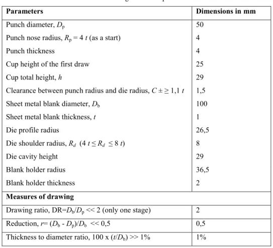
The most relevant dimensions considered in the present study of the punch (A), blank holder (B), sheet metal blank(C) and die (D) are shown in table 1, (Evangelista, 2000). The blank then has the same weight as the cup. A blank of correct thickness would be cut to the diameter necessary to produce this weight (Gyadari, 2013). Several formulas are available for calculating the blank diameter, as follow:
Db= (Dp2 + 4Dp h)1/2 (1)
Table 1 Basic geometrical parameters
&-&4+%+-) 4+!) #!) ! 44
Punch diameter, Dp
Punch nose radius, Rp = 4 t (as a start)
Punch thickness
Cup height of the first draw
Cup total height, h
Clearance between punch radius and die radius, C ± ≥ 1,1 t 50 4 4 25 29 1,5
Sheet metal blank diameter, Db
Sheet metal blank thickness, t
100
1
Die profile radius
Die shoulder radius, Rd (4 t ≤ Rd ≤ 8 t)
Die cavity height
26,5
8
29
Blank holder radius
Blank holder thickness
36,5
2
+&)$-+) #5 ,-&6 !7
Drawing ratio, DR=Db/Dp << 2 (only one stage) 2
Reduction, r= (Db Dp)/Db << 0,5 0,5
Thickness to diameter ratio, 100 x (t/Db) >> 1% 1%
Topic A: Computational Mechanics
89
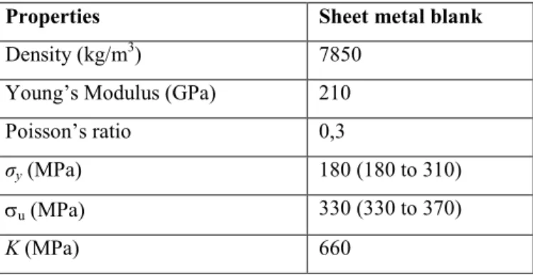
Carbon steel plate material SAE AISI 1008 for sheet metal blank stamping is used. The mechanical properties are summarized in table 2, where σy is the yield stress, σu is the ultimate tensile strength and K the strength coefficient.
Table 2 Material properties for steel alloy (AISI 1008)
-#:+-% +) ;++% 4+%&. <.&!=
Density (kg/m3) 7850 Young’s Modulus (GPa) 210
Poisson’s ratio 0,3
σy (MPa) 180 (180 to 310)
σu (MPa) 330 (330 to 370)
K (MPa) 660
From an analysis of the forces in equilibrium during the formation of a deep drawn cup, the use of an approximate equation for the total punch force as a function of the diameter of the blank at any stage in the process. An approximate equation of the maximum drawing force F
(in N) or punch load has been developed (Schey, 1987), (Groover, 2010), (Tschaetsch, 2005), (Kumar, 2016):
F = πDptσu (Db/Dp C) (2)
C is a constant between 0,6 to 0,7, (Chaudhari,2016), (Kumar, 2016). The drawing force F
varies throughout the downward movement of the punch, usually reaching its maximum value at about one third the length of the punch stroke (Groover, 2010). A factor of safety should be taken. In the study case the draw force was equal to 80,8kN (=67,4kN x 1,2).
A holding force was applied directly on the blank holder, usually represents 33% of the drawing force (Fh=33% x 80,8= 26kN), (Kumar, 2016). According the dimensions and the material, the calculated holding force was equal to 26kN. The holding force Fh (in N) is an important factor in drawing operation.
In the case of low blank holder force there is wrinkle usually in the flange of the drawn part, when increasing wrinkle is reducing. But large value of the blank holder force will cause fracture in the material. The press force capacity can be calculated by using the adding between the draw force using a safety factor and the blank holding force, (Chaudhari,2016). In the study case the value is equal 108kN (or 11 ton). Other considerations should be considered in deep drawing to control the sheet metal fracture, as excessive friction between blank and punch, insufficient clearance between punch and die and insufficient punch or die corner radius.
Proceedings of the 7th International Conference on Mechanics and Materials in Design
8
forging, deep drawing, multi scale processes) predicting the level of stresses and deformations in the metallic material and determine if the metal will fail, (Abdulla, 2013).
Explicit scheme is a function of time, where the velocity and acceleration as well as the mass and damping need to be considered in this scheme. Central difference time integration is used to calculate field variables at respective nodal points, particularly suited for nonlinear problems. The equation of motion is evaluated at the previous time step and works in time step increments, where the displacements are calculated as the time proceeds. Gradually as time would progresses the deformation also would change. The time step for implicit solvers is about two to three orders of magnitude of the explicit time step. The explicit solvers are best suited to treat problems of short duration, with high loading velocity and highly nonlinear nature that require small time steps for accuracy reasons.
The proposed numerical model intents to simulate the stamping process, as a practical problem with industry interest, and to evaluate the mechanical stress and deformation in stamping piece. The input die assembly model (die, blank, blank holder and punch) were constructed in pre processor using tool CAD geometry in the FEM program. After the generated CAD model, a fine meshing is created.
Figure 2 represents different meshes used in this work. In all simulations the complete die face design composed of the punch (A), binder or blank holder (B) and the die geometry (D) is assumed to be rigid components. The sheet metal blank material (C) is the high strength steel of thickness 1mm.
(I): 3D quarter: Solid164 (8nodes) / Shell163 (4nodes) (II): 3D quarter: Solid164 (8nodes) (III): 2D Axisymmetric: Plane162 (4nodes)
Fig. 2 Different meshes of die assembly,
(A Punch, B Binder or Blank Holder, C Sheet metal blank, D Die).
Topic A: Computational Mechanics
8
All boundary conditions will be considered due the geometry and dynamics characteristics involved in the process. In 3D problem only a quarter of the geometry was modelled and symmetry boundary conditions used. In 2D problem due to axisymmetric boundary conditions the central left region nodes will not move in the left direction due to the constraint.
For dynamic process, punch is displayed vertically downwards to establish contact with the blank with a punch speed equal to 1,7m/s. To improve the material flow control, a constant blank holder force is used, equal to Fh=26kN and applied vertically in binder to simulate a contact between the blank holder and the blank.
In ANSYS contact interaction between all components in die assembly was formulated using the *CONTACT_AUTOMATIC_SURFACE_TO_SURFACE, generally recommended for this type of process. Thus, by choosing automatic surface to surface contact, the program will automatically adjust for the changes which occur during this simulation.
Contact assuming Coulomb friction between the blank, punch, die surface and the blank holder was modelled. In ANSYS its behaviour can be controlled with the parameters on the *CONTACT_... card: static and dynamic friction coefficients, exponential decay coefficient and coefficient for viscous friction. It is required the definition of the frictional coefficients. Dynamic friction coefficient between the blank and the die surface was very low (friction coefficient 0,04 or lower) due to the lubricant (Yasar and Kadi, 2007). The dynamic friction coefficient between the blank and the blank holder and the punch was assumed with the same value equal to 0,04. Static friction coefficient between all components for cold working was equal to 0,1 (Groover, 2010).
Also, time step size is automatically adjusted to satisfy the contact between different bodies and the program checks all elements when calculating the required time step. In explicit analysis, the time step is affected by element size and material sound speed. For stability reasons, a scale factor (0,9) is used to decrease the time step. In all simulations the time step used was equal to 0,00015s until end time 0,015s, estimate time due the cup height and the punch speed.
To define the material model of the metal should be taken in consideration the strain rate with dependency of the isotropic material plastic curve. The rate sensitive power law plasticity model is a strain rate dependent plasticity model typically used for superplastic forming analysis. The sheet metal blank is made of a steel alloy material that is assumed to satisfy the stress strain curve Ramburgh Osgood as constitutive relationship, (Groover, 2010):
σ=K εmεn (3)
where σ is the stress; K is the reference stress value or strength coefficient; m the hardening coefficient equal to 0,012; n is the strain rate sensitivity coefficient considered 0,19; ε the true strain and ε the initial strain rate considered equal to 30, (Evangelista, 2000). All these parameters permit to identify the correspondent plastic flow curve.
Proceedings of the 7th International Conference on Mechanics and Materials in Design
8
The main objective is the numerical model forming a cylindrical cup of 50 mm diameter and 25 mm deep in 0,015s. Deformed shapes of the blank at different drawing depth are presented in figure 3, for each numerical model. Models (I) (II) and (III) were simulated with a complete die assembly including the blank holder and the effect of the applied holding force. Also, only the Model (I) was simulated without the blank holder part to verify the flange wrinkling effect during the sheet metal forming.
Die assembly
without blank holder Die assembly with blank holder and applied holding force
#,+. / 1 #,+. / 1 #,+. / 1 #,+. / 1
Time=0,00495s
Depth=0,00809m
Time=0,00495s
Depth=0,007982m
Time=0,00495s
Depth=0,007458m
Time=0,00495s
Depth=0,007445m
Time=0,01095s
Depth=0,018229m
Time=0,01095s
Depth=0,018069m
Time=0,01095s
Depth=0,017764m
Time=0,01095s
Depth=0,017697m
Time=0,015s
Depth=0,025127m
Time=0,015s
Depth=0,024939m
Time=0,01155s
Depth=0,018833m
Time=0,015s
Depth=0,024616m
Fig. 3 Different deformed shapes of the blank
Topic A: Computational Mechanics
8>
In all meshes until time instant to obtain 18mm drawing depth the results are in good agreement, but increasing the time punch progression the results become no closer to a converging values.
Shell elements in model (I) allow the modelling of thin blank with fewer elements than solid elements, easier to mesh and less prone negative Jacobian errors, which might occur when using thin solid features. 3D solids elements are best for thick combinations.
Model (I) without the blank holder intends to demonstrate the instability effect in the body of the piece with a deep drawing simulation. It is necessary blank holder load to prevent wrinkling. Increasing this force by using a blank holder of an appropriate size will ensure a reduction in wrinkling height, (Patel, 2014).
Figure 4 represents the distribution of equivalent plastic strains for successive trails of the stamp falling in time instants in expanded model. Maximum plastic deformations are observed with red colour region or in grey colour with higher values than model (I). The blue colour represents minimum strains in the sheet metal blank. In this study, generally maximum strain occurs on the lateral wall cup where tension in side wall is higher.
Die assembly with blank holder and applied holding force
#,+. / 1 #,+. / 1 #,+. / 1
Time=0,00495s Time=0,00495s Time=0,00495s
Time=0,01095s Time=0,01095s Time=0,01095s
Time=0,015s Time=0,01155s Time=0,015s
Proceedings of the 7th International Conference on Mechanics and Materials in Design
8
The results from the numerical simulations produced comparisons between all types of finite element models. And it was observed that there was a good correlation between all different simulations until time instant to obtain a cup of 18mm drawing depth.
This study shows the finite element procedures for the sheet metal forming process and presents the performance of the use of axisymmetric conditions in the balance of the computational requirements against the desired accuracy of the results.
With numerical simulations it is possible to observe the quality of the piece according the thickness distribution, and also detects some defects like wrinkling, crushing and tearing material.
[1] A. Praveen Kumar, M. Nalla Mohamed. A novel automated design calculating system for axisymmetric thin walled structures by deep drawing process. Journal of Advanced Engineering Research, 3(2), pp.128 133m 2016.
[2] Abdulla Shaikh & Tippa Rao. Sheet Metal Forming Simulations for Heavy Commercial Vehicle Parts by LS_DYNA. Global Journal of Researches in Engineering (B), 2013, 13(1), p. 35 40.
[3] George E Dieter, JR. Mechanical Metallurgy. McGraw Hill Book Company, New York, 1961.
[4] Gyadari Ramesh, Chandra M Reddy. Analysis of Optimization of Blank Holding Force In Deep Drawing by Using LS DYNA. International journal of Engineering, 2013, 3(4), p. 1975 1995.
[5] Heinz Tschaetsch. Metal Forming Practise. Fourth Edition, Springer, New York. 2005.
[6] M. Firat. Computer aided analysis and design of sheet metal forming processes: Part I The finite element modelling concepts. Materials & Design, 2007, 28, p. 1298 1303.
[7] Mikell P. Groover. Fundamentals of Modern Manufacturing. Fourth Edition, John Wiley & Sons, Inc. 2010.
[8] Mustafa Yasar and Ibrahim Kadi. High Velocity Forming of Aluminum Cylindrical Cups Experiments and Numerical Simulations. J. Mater. Sci. Technol., 2007, 23(2), p. 230 236.
Topic A: Computational Mechanics
88
[10] Ranganath J et al. Finite element method for simulation of a rectangular tank with an integral flange for automotive application. International Journal of Engineering Research & Technology, 2012, 1 (5), p. 1 10.
[11] Sérgio H Evangelista. Diagramas de limite de conformação aplicados à análise por elementos finitos de um processo de estampagem em chapas metálicas. Dissertação apresentada à Universidade de São Paulo, Escola de Engenharia de São Carlos, 2000.
[12] Schey. Introduction to Manufacturing Processes. McGraw Hill Public, 1987.