Multistage Deep Drawing with Ironing of Al-killed AISI 1040 Graded Medium Carbon
Steel: a Parametric Study
Anil Kumar Paridaa,b, Shatrughan Sorenb*, Raghu Nandan Jhaa, Nelepu Krishnamurthyc
Received: August 08, 2016; Revised: March 31, 2017; Accepted: May 21, 2017
Analysis of multistage deep drawing with ironing was made while manufacturing of cups from 12 mm thick, 60 mm diameter circular blanks of Al-killed AISI 1040 graded medium carbon steel. Quality requirements of the steel in heat treated condition were examined in terms of tensile properties, formability characteristics, and formability limit diagram. Drawability and ironability parameters in multistage cup drawing processes were evaluated in terms of draw ratio; draw reduction; ironing ratio; ironing reduction and thus its press formability in an actual state of practice was shown. Further, were analysed the inluences of process parameters such as: semi die angle; interfacial friction coeicient; die-punch clearance on draw and ironing punch forces in each draw stage. The spring back tendency of cups in terms of their trends and degrees with respect to cup heights and draw stages were experimentally determined by conducting split ring test. Thus, a data bank was created as potential references for process engineers to improve the manufacturing process and draw tools as well, particularly for the selected steel.
Keywords: Medium carbon steel, Formability, Multistage deep drawing, Wall ironing, Process parameters, Spring back behaviour
* e-mail: [email protected]
1. Introduction
Steel cylindrical cups are widely used in automobile sectors, defence applications and other industries. While demand of these cups increases rapidly, the process optimization in manufacturing practice still needs more development in order to reduce lead-time, improve productivity and ensure product quality. Such products are manufactured by multi-stage deep drawing, which is sometimes accompanied with wall ironing technique for achieving uniform wall thickness and increased cup length. Since these processes are involved with a complicated deformation mechanism, the inal mechanical properties are diicult to predict and also process design is not easy for manufacturing cups successfully with the desired shape and properties. Success or failure of metal forming by deep drawing accompanied with wall ironing is inluenced by various process parameters such as: degrees and ratios of drawing as well as ironing; die entry semi-angle; die-punch clearance; interfacial friction coeicient; inherent material properties like strength, strain hardening exponent, formability and so forth.
Because of the importance of deep drawing as well as ironing, the process (either by separately or in a combination) is being the subject of many experimental and theoretical investigations1-15. Many of these investigations have dealt
with low strength metals with high formability, like: diferent grades of low carbon steels and aluminium alloys etc. To the best knowledge of authors’, a study on efects of process parameters in manufacturing of cups from high strength metals is less attended, while medium carbon steel processed by multistage deep drawing accompanied with ironing method is found rarely available. Further, an application of 12 mm thick circular blanks for drawing long cylindrical cup is seen almost nonexistent. Such lack of information possibly arise a need of this investigation work to ill up the knowledge gap and create a databank as potential reference for process engineers to optimize manufacturing processes in deep drawing, automobile and defence industries.
The present paper is describing inherent material properties of aluminium (Al) -killed AISI 1040 graded medium carbon steel and thus input quality requirements are indicated for cup manufacturing from 12 mm thick circular blanks of 60mm diameter. The degree of press formability of the steel while applied in a 3-stage deep drawing and ironing processes were evaluated in terms of Drawability and Ironability parameters. The efects of process parameters such as: semi die angle(α), interfacial friction coeicient (μ), and die-punch clearance (c) were analyzed by varying them and thus inluences on
punch forces were identiied. Also, by split ring test, spring
a Metal and Steel Factory, Ishapore, 743144, India
back behaviour of cups was determined for tool optimization, a future scope of work.
2. Material and Methods
2.1. Material
The chemical composition of the as received Al -killed AISI 1040 graded medium carbon steel is reported in Table 1. The basic input material as 15% cold reduced 14 mm thick strips were used for cup drawing after subjecting to a heat treatment cycle consisted with hardening (heating at 1133ºK for 1 hour and water quenching) followed by a prolonged tempering (heating at 923ºK for 36 hours, followed by furnace cooling to 472ºK and air cooling to the room temperature).
2.2. Mechanical properties and formability
parameters evaluation
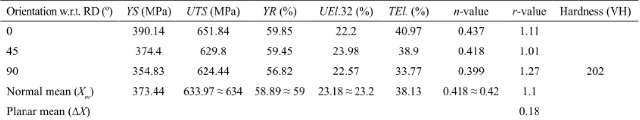
Intrinsic mechanical properties of the steel in heat treated condition were determined by tensile test at ambient temperature (298ºK) on lat specimens (5 mm thickness, 6.5 mm width and 32 mm gauge length) along 0º, 45º, and 90º to the rolling direction (RD), by using a 20kN, KIL make (model PC 2000) electronic tensometer, at a strain rate 2.5 x 10⁻⁴ s-1,according to standard IS 1608: 200516. True values of tensile properties, yield strength (YS); tensile strength (UTS); yield ratio (YR); uniform elongation (UEl.); total elongation (TEl.) were determined from load-extension curves. The strain hardening exponent (n), an indicator of formability, was evaluated by regression method, applying on tensile low curves. The uniaxial formability parameters such as: normal anisotropy (rm) and planar anisotropy (∆r) values were evaluated by conducting tensile tests up to an elongation just 2-3% below uniform elongation and using the following equations as per standard IS 11999: 200717.
The formability limit curve (FLC) was determined by conducting Erichsen cup test at ambient temperature (298ºK), as per Indian standard IS 10175(Part 1): 199318, by an electro-hydraulic drive Erichsen sheet metal testing machine (Model-140, drawing force 0-30 kN, sheet holding force 0-34 kN), assembled with die-punch arrangements (Figure 1a). The test was done on 2 mm thick steel specimens of varying widths, 75 mm, 56 mm, 38 mm, 21 mm and 15 mm, which were printed with 2.5 mm square grids (equivalent to grid circles of 2.5 mm diameter). More importantly, these 2 mm thick specimens were cut from the steel strips by using CNC Wire-cut EDM machine, followed by grind inish. Proper precautions were taken during sample preparation to maintain intact condition of the inherent material properties. In order to obtain maximum values in the magnitude of negative minor strains, uniaxial tension tests were also done using grid-marked specimens. These tests were conducted up to failure or to localized necking in some cases.
Table 1. Chemical composition of Al-killed AISI 1040 steel (in % wt.).
Elements C Mn Si S P Ni Cr Mo Al Cu Sn As Sb Fe
wt% 0.39 0.79 0.34 0.009 0.005 0.12 0.18 0.10 0.05 0.08 0.0059 0.0053 0.0018 Bal.
Note: H, O and N are 1.8, 18.4 and 82.3 ppm respectively; Bal. = balance quantity.
Where, r = plastic stain ratio; Ԑw = plastic strain along width; Ԑt= plastic strain along thickness; w0, t0= width, thickness respectively of the specimen before test; w, t = width, thickness respectively after test.
Then rm and ∆r -values were calculated using standard formulae17 as follows:
Where, the subscripts, 0º, 45º and 90º are orientations to the RD of the steel strips.
Figure 1. (a) Schematic showing of Erichsen cup test arrangements;
(b-f) photo images of Erichsen cup specimens of diferent widths. / ln( / )/ln( / ) ( )
r=
f f
w t= W0 W t0 t 1( )/ ( )
rm= r0+2r45+r90 4 2
/ ( ) r r0 r90 2r45 2 3
True major (Ԑ1) and minor (Ԑ2) strains were calculated from measurements of deformed grids19-21 on specimens after testing (Figures 1b-f) and were expressed in a 2D strain space, known as formability limit diagram (FLD) 22. A line was drawn just below the points under visible necking as well as of the fracture zone, known as formability limit curve (FLC).
2.3. Multistage cup drawing
Cup drawing experiment were conducted by multistage (three stages) deep drawing with simultaneous ironing processes on high speed mechanical press machines, without using blank holders, considering relatively thicker blanks23. The processing steps which were followed during the experiment such as: blanking for forming of circular blanks - facing of blanks at both sides - stress relieving, surface treatment and lubrication - stamping for pre-forming of blanks - stress relieving, surface treatment and lubrication - 1st draw - stress relieving, surface treatment and lubrication - 2nd draw - stress relieving, surface treatment and lubrication - 3rd as inal draw - stress relieving treatment. After each step of press work, thecomponents were stress relieved with a heating cycle, 933-983ºK for 4 hours - furnace cooling to 473ºK - air cooling to room temperature, to eliminate strain hardening efect24. On completion of stress reliving, components were undergone an intermediate surface treatment by acid pickling (HCl: 6-7%, PH: 2-5) for removal of oxide coating; phosphating for ensuring a 5-10 µm thick porous layer to enhance lubricant carrying ability of the surface during press work; lubricating by immersing in soap solution (33% soap lakes) for 2 hours in order to ensure a complete difusion of the solution into the pores of phosphate coating layer.
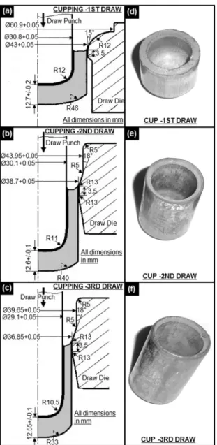
Circular lat blanks of 60 mm diameter were cut from 14 mm thick heat treated strips by blanking operation on a 500 tons high speed mechanical press with blanking tools, schematically shown in Figure 2a. Blanks thus produced (Figure 2c) were undergone surface machining (facing) at both sides up to 12 mm thick, in order to discard the decarburized surface layer generated during heat treatment. Before taking into cupping process, these circular lat blanks were undergone to a stamping operation, schematically shown in Figure 2b, on a 250 tons mechanical press to give a preformed shape (little draw-in shape with a concave radius, R13), shown in Figure 2d. The preformed blanks (Figure 2d) were then subjected to 3-stage cup drawing experiment by using high speed mechanical press machines of 500 tons in the irst draw, 350 tons in the second draw and 250 tons in the third draw. Figures 3a-cshow the schematic arrangements of the stage wise tooling, Table 2 illustrates all involved process parameters, and Figures 3d-fexhibit the photo images of cups drawn in each draw step.
The dimensions of drawn cups were measured by digital micrometers and vernier callipers after sectioning the cups at
Figure 2. Schematically showing of arrangements, (a) blanking,
and (c) stamping; Photo images, (b) circular lat blank, and (d)
preformed blank.
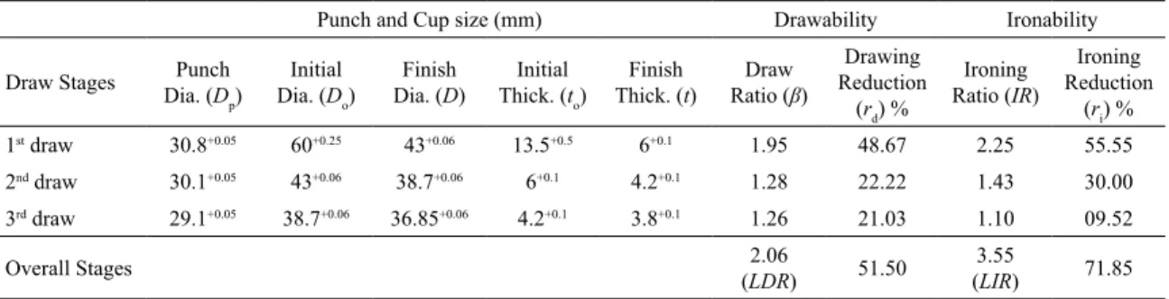
middle portion. Based on dimension of components and draw tools used in a stage, Drawability and Ironability parameters were evaluated for the respective draw stage by using few standard formulae obtained from diferent literatures.
The efects of diferent process parameters such as: semi die angle (α), interfacial friction coeicient (μ), and die-punch clearance (c) on particularly on punch forces (draw and ironing punch forces) in each draw stage were analyzed based on standard force equations found from literatures.
Further, the spring back tendency of the drawn cups along their walls in each draw stage were determined by a simple and repeatable Demeri split ring test. The test was conducted, as described by Foecke and Herold25; Danckert26, on ring specimens (7 mm wide) cut from the drawn cups, at diferent heights and then were mechanically slitted longitudinally along their radial planes, schematically shown in Figure 4. Thus resulted gaps of splitted rings were evaluated by measuring diferences between ring diameters, i.e. before and after splitting and expressed as the spring back tendency of the drawn cup walls.
3. Results and Discussions
3.1. Mechanical properties and formability
Where, D0=diameter of the blank (before cupping); Di, Di-1=outer diameter of the cup after and before the stage -(i) respectively; DP-i, DP-f =diameter of punch in the stage -(i) and the inal stage respectively; T0=thickness of the blank (before cupping); Ti, Ti-1 and Tf =thickness of cup wall in the stage -(i), -(i-1), and the inal stage respectively.
Table 4 also depicts values of drawability and ironability parameters under which the cups are drawn. It shows the maximum values of ratios, β and IR, in the irst draw stage and their decreasing trend is observed in subsequent stages. The stage wise variation of reduction parameters (rd, ri), demonstrates a similar trend as found for ratios. This tendency is as expected from the process design, ensuring uniform distribution of deformation among three diferent draw steps. Considering the overall draw steps, the calculation shows the LDR value, 2.06; the LIR value, 3.55; the overall draw reduction (rd-o), 51.5% and the overall ironing reduction (ri-o), 71.85%, which conirm good press formability of the steel in actual state of application.
3.3. Inluence of various process parameters on
punch forces
Efects of diferent process parameters, such as: semi die angle (α); interfacial friction coeicient (μ); die-punch clearance (c), on draw and ironing punch forces were analyzed by varying their values separately and applying in the draw and ironing punch force equations, while the other parameters kept constant. The following standard punch force equations were obtained from diferent related Figure 3. 3-stage cup drawing, (a-c) schematically showing of
arrangements; (d-f) photo images of drawn cups.
dispersibility19, 27-29. The uniaxial formability characteristics evaluation shows its rm -value, 1.1 (>1), and ∆r -value, 0.18, imply that the steel has moderate drawability with good earing resistance.
The FLD is graphically represented in Figure 5 wherein the true FLC distinguishes a safe forming zone of the steel under investigation. The lowest forming limit has been observed at plain strain condition (Ԑ2= 0) 19, showing the true FLC0 = 33.451%, which is signiicant.
3.2. Drawability and ironability (press formability)
Table 4 summarizes cup dimensions obtained in 3-stage cup drawing experiment. By using these data in Equations 4-112,11,30,31, various drawability and ironability parameters were evaluated for each draw step.
( ) / ( )
Draw ratio b =Di DP i- 4
, . .
( ) / ( )
Overall draw ratio limiting draw ratio
i e
LDR D DP f 5 o 0 b =
-Q V
( ),% ( )/ ( ) Draw reduction x rDi DP i Di 100 6
d 1 1 = -- - -"
$
( )% / ( )Overall draw reduction x
r
D D D 100 7
d P f o 0 0 =
-Q
V
" % ( ) / ( )Ironing ratio IR =Ti-1 Ti 8
( ),%
/ ( )
Ironing reduction x
r
T T T 100 10
i
i 1 i i1
= --
-Q
V
" % ( )% / ( )Overall ironing reduction x
r
T T T 100 11
i o f 0 0 =
-Q
V
" % ( ), . . ( ) / ( ) limOverall ironing ratio it ironing ratio
IR i e
LIR T Tf 9
o
Table 2. Equipments, tools and process parameters used in 3-stage cup drawing operations.
(a) Equipments/tools (b) Technical details/process parameters
A Press machine
First draw: Capacity- 500 Tons, crank type mechanical press of single action, stroke length- 200 mm, and ram speed- 83 mm.s-1.
Second draw: Capacity- 350 Tons, crank type mechanical press of single action, stroke length- 610 mm, and ram speed- 183 mm.s-1.
Third draw: Capacity- 250 Tons, crank type mechanical press of single action, stroke length- 640 mm, and ram speed- 192 mm.s-1.
B Draw die
Die Proile: schematically shown in Figs. 3(a), (b) and (c) for irst, second and third draw stages respectively.
Surface inish: grind inish with polished surface at the efective working zones.
Die material: IS: T108/ JIS: SK 3, 4 steel.
Die hardness: 578-652 BHN on hardened and tempered condition.
C Cupping punch
Punch proile: schematically shown in Figs. 3(a), (b) and (c) for irst, second and third draw stages respectively.
Surface inish: grind inish with polished surface at the efective working zones.
Punch material: IS: T108/ JIS: SK 3, 4 steel.
Punch hardness: 578-652 BHN on hardened and tempered condition.
D Stripper (three parts segmented type)
First draw: 31.8+0.06 mm (min.) diameter. Second draw: 31.2+0.06 mm (min.) diameter. Third draw: 30.5+0.06 mm (min.) diameter.
(Stripers are itted at the exit end of draw dies, with peripheral spring tension for extraction of the drawn
cups after each stage of drawing).
E Die-punch clearance
First draw: 6.00+0.10 mm. Second draw: 4.20+0.10 mm. Third draw: 3.80+0.10 mm.
F Lubricant Water diluted soap lakes [33% Sodium oleostearate, technical (soap noodles) as per IS 10513-1983, Table 1, clauses 4.4, 8.1 and 8.3, type-1 and 67% H2O].
Figure 4. Schematically showing of split ring test schedules.
Table 3. Tensile properties and formability characteristics of Al-killed AISI 1040 steel strips in heat treated condition.
Orientation w.r.t. RD (º) YS (MPa) UTS (MPa) YR (%) UEl.32 (%) TEl. (%) n-value r-value Hardness (VH)
0 390.14 651.84 59.85 22.2 40.97 0.437 1.11
202
45 374.4 629.8 59.45 23.98 38.9 0.418 1.01
90 354.83 624.44 56.82 22.57 33.77 0.399 1.27
Normal mean (Xm) 373.44 633.97 ≈ 634 58.89 ≈ 59 23.18 ≈ 23.2 38.13 0.418 ≈ 0.42 1.1
Planar mean (∆X) 0.18
Note: Xm = (X0 + 2X45 + X90)/ 4; ∆X = (X0 - 2X45 + X90)/ 2; UEl32, Uniform elongation in 32 mm; r-value measured at 16-17% of UEl.; n.r = Overall press performance factor.
literatures, wherein assumed a plain strain condition, because of circumference of the cup wall was constrained by the rigid punch from shrinkage and thus yielded of a negligible (≈0) circumferential strain.
The draw punch force in irst draw stage was calculated by Equation 12, described by Boljanovic31.
[{ .( . ). ( / )}.
.( . / )] [ ] ( )
ln exp
P D t k D D
B 1 1
2 12
D 1 r P f m 0 P
n r =
+
-
-Where, DP =punch diameter, D0 =blank diameter, t =wall thickness, kf-m =average low stress (MPa), μ =coeicient of
friction at die radius and was assumed ≈0.1631, B =force to bend and re-straighten the blank in cup forming.
The average low stress, kf-m was calculated by using the Equation 1332:
( )/ ( )
kf m- = kf-0+kf-1 2 13
in MPa (calculated by Equation 16 assuming kf-0 =yield stress of the material because of stress relieving treatment after drawing), μ =interfacial friction coeicient, assumed as ~0.1631.
The ironing punch force in each draw step was evaluated by Equation 16, described by Folle et al.7.
Figure 5. Graphical showing of FLD, plotted from Erichsen cup test.
Table 4. Drawability and Ironability obtained in 3-stage cup drawing processes.
Punch and Cup size (mm) Drawability Ironability
Draw Stages Punch
Dia. (Dp)
Initial Dia. (Do)
Finish Dia. (D)
Initial Thick. (to)
Finish Thick. (t)
Draw Ratio (β)
Drawing Reduction
(rd) %
Ironing Ratio (IR)
Ironing Reduction
(ri) %
1st draw 30.8+0.05 60+0.25 43+0.06 13.5+0.5 6+0.1 1.95 48.67 2.25 55.55
2nd draw 30.1+0.05 43+0.06 38.7+0.06 6+0.1 4.2+0.1 1.28 22.22 1.43 30.00
3rd draw 29.1+0.05 38.7+0.06 36.85+0.06 4.2+0.1 3.8+0.1 1.26 21.03 1.10 09.52
Overall Stages 2.06
(LDR) 51.50
3.55
(LIR) 71.85
Note: LDR = limit draw ratio, and LIR = limit ironing ratio.
the equation of low stress curve, i.e kf = C.φPn 32, where, φ P =principal strain, C = strain hardening coeicient and n =strain hardening exponent.
The bend force, B, was calculated by using the Equation 1430: [( . . )/ ( . )]
( / ) ( )
tan x
B k L t 2 R 0 5t
2 14
f m 2 d
c
= - +
Where, L = total length to bend i.e. perimeter (πD0) of the preformed blank =189.12 mm, t = thickness of the preformed blank (13 mm, the average measured thickness at the zone under bending action), Rd =bend radius i.e. die radius (R12),
γ =bend angle i.e. 90º in the present investigation. Draw punch forces in second and third draw stages were evaluated by Equation 15, described by Boljanovic31.
[ ] [ . { ( / )} {( . / . ) } { ( / )} { ( / ) }] ( ) tan x x x x
P D t
k
D D
1 1 1 2 180
1 21 1 44 1 2
1 ( ) ( /tan ) 15
i P i i
f m
m i m i 1 2
r nr a
a n
= +
+
- n a
--
-Where, i = draw stage no., Pi = punch force in i -stage, DP-I =punch diameter in i -stage, ti = cup wall thickness in i –stage after drawing, Dm-i=mean dia. of cup after drawing in i -stage, Dm-(i-1) = mean dia. of cup after drawing in (i-1) -stage, α =semi die angle in degree, kf-m = average low stress
[ / / ] ( )
F=kf m- Ai P{ 1+n a+2a 3{P 16
Where, kf-m =mean low stress in MPa (Equation 13), Ai = cross-sectional area of the cup after ironing in i -stage,φP = principal strain, α =semi die angle in degree, μ = interfacial friction coeicient, assumed as ~0.1631.
3.3.1. Inluence of process parameters (α, μ, c) on draw punch forces
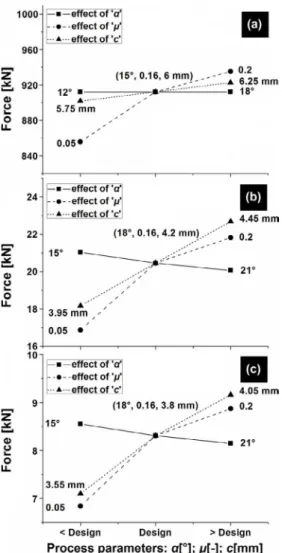
Figure 6a shows inluences of semi die angle (α); interfacial friction coeicient (μ); die-punch clearance (c) on draw punch force in irst draw stage, where trends of the force are plotted against varying values of α; μ; c i.e. less than, equal to and greater than design values of the respective parameter. From igure, it is observed that the semi die angle has almost nil efect on force, which is as expected from the force equation used in the equation, considering non steady state of deformation in the stage. It is also seen that the draw force gets mounted on an escalation ofboth the interfacial friction coeicient and the die-punch clearance. Moreover, the friction coeicient is found to be the most inluential factor among all.
Figures 6b-crepresent the efect of the process parameters on draw punch forces in second and third draw stages respectively, wherein the semi die angle is found inluencing inversely the force in both the stages unlike to the irst stage. Herein both stages, the die-punch clearance is found as the largest inluential parameter and the interfacial friction coeicient is next to it.
3.3.2. Inluence of process parameters (α, μ, c) on ironing punch forces
Figure 6. Graphical showing of inluences of process parameters (α;
μ; c) on draw punch force, (a) 1st draw, (b) 2nd draw, and (b) 3rd draw.
Figure 7. Graphical showing of ironing punch force inluenced by, (a-c) semi die angle (α); (d-f)
interfacial coeicient of friction (μ); (g-i) die-punch clearance (c), in 1st draw, 2nd draw and 3rd
draw respectively in each case.
to thickness reduction during the process. Since at initial stage while the material entering the die, the cup thickness doesn’t reduce instantly, therefore no strain is shown. As the material passes through the die, there is a sudden rise in the ironing force up to a value indicated in the igure. Herein the force is observed going up by increasing the value of ‘α’.
Figures 7b-cpresent the inluence of semi die angle (α)on ironing forces in second and third draw stages respectively, with respect to thickness reductions in the stages. Herein both the stages, forces show a trend similar to the irst draw stage, but at diferent degrees. Further, on advancement of the draw stages, levels of these forces are found reducing, attributed by decreasing values of the thickness reductions. Figures 7d-fillustrate the efects of interfacial friction coeicient (μ) on ironing forces in irst, second and third draw steps respectively. Herein, it is distinguished that the friction coeicient between the material and the die has not inluenced the forces convincingly in all three stages, which perhaps due to the high values of forces have rendered comparatively very small deviations to the respective force lines and thus these lines have almost coincided with each other. Hence the process parameter,‘μ’ can be considered as of very little efect on the ironing force, although a reverse trend has been witnessed in case of the draw punch force is concerned, discussed in the earlier section.
the forces, which would cause to be consequent excessive wear on die-punches.
Figures 8a-c display the efects of these three process parameters (α, μ, c), all together, on ironing forces in irst, second and third draw stages respectively. An analysis of these igures reveals that the semi die angle (α) has inluenced the forces with a maximum efect in all the draw stages, whereas the friction coeicient (μ) is with the least efect.
Figure 8. Graphical showing of inluences of three process parameters (α, μ, c) all together on ironing punch force, (a) 1st draw, (b) 2nd
draw, and (b) 3rd draw.
3.4. Spring back tendency of cup walls
Figure 9 shows the trends and degrees of spring back tendency of cup walls (in irst, second and third draw stages) with respect to their heights from bases. Herein, lines connected to data points indicate to an increasing propensity in spring back behaviour of cups in every draw stage, agreed by Foecke and Herold25.Moreover, it is also observed that the degree of spring back tendency reduces on advancement of
Figure 9. Schematically showing of spring back behaviour of cup walls in terms of split ring gaps (1st-2nd-3rd draw).
draw steps, which perhaps due to decrease in residual hoop stresses on cup walls, caused by increasing predominance of wall ironing26 in second and third draw steps.
4. Conclusions
• A typical heat treatment cycle i.e. hardening by water quenching followed with a long (36 hours) tempering at higher temperature (923ºK), applied on the selected medium carbon steel (Al-killed AISI 1040 grade) strips, has provided a good combination of strength-ductility-formability, which indicates its cup drawing applicability with moderate drawability and a maximum strength up to ~634 MPa. • The multistage deep drawing with simultaneous
ironing process applied on 12 mm thick, 60 mm diameter circular steel blanks has shown a good press formability of the steel by rendering overall draw reduction, 51.5% with LDR, 2.06 and overall ironing reduction, 71.85% with LIR, 3.55, those have been achieved in the investigation held in three potential draw steps.
• For all three draw stages, the degree of spring back tendency of cups were found increasing with increasing cup heights from their bases, while they reduced on advancement of draw stages from irst to third one.
• The databank created in the investigation can be gainfully exploited for further improvement in process optimization and tool designing in manufacturing of cups from the steel.
5. Acknowledgements
The steel was supplied by Metal & Steel Factory, Ishapore, West Bengal, India and the experimental facilities were also extended by them. The authors gratefully acknowledge this.
6. References
1. Anaraki AP, Shahabizadeh M, Babaee B. Finite element simulation of multi-stage deep drawing processes & comparison with experimental results. World Academy of Science, Engineering and Technology. 2012;61:670-674.
2. Jawad WK.Design modiication in a multi-stage deep drawing process. Engineering & Technology Journal. 2008;26(1):29-44.
3. Kim SH, Kim SH, Huh H. Tool design in a multi-stage drawing and ironing process of a rectangular cup with a large aspect
ratio using inite element analysis. International Journal of Machine Tools and Manufacture. 2002;42(7):863-875.
4. Chang DF, Wang JE. Inluence of process parameters on the
ironing of deep-drawn cups. Journal of Manufacturing Science and Engineering. 1997;119(4B):699-705.
5. Gotoh M, Kim YS, Yamashita M. A fundamental study of can forming by the stretch-drawing process. Journal of Materials Processing Technology. 2003;138(1-3):545-550. DOI: 10.1016/ S0924-0136(03)00144-4
6. Rubio EM, González C, Marcos M, Sebastián MA. Energetic
analysis of tube drawing processes with ixed plug by upper
bound method. Journal of Materials Processing Technology. 2006;177(1-3):175-178. DOI: 10.1016/j.jmatprotec.2006.03.193
7. Folle LF, Netto SES, Schaefer L. Analysis of the manufacturing
process of beverage cans using aluminum alloy. Journal of Materials Processing Technology. 2008;205(1-3):347-352. DOI: 10.1016/j.jmatprotec.2007.11.249
8. Courbon J. Damage evolution in a compressive forming process: ironing of beverage cans. Scripta Materialia. 2003;48(11):1519-1524. DOI: 10.1016/S1359-6462(03)00131-3
9. Jain M, Allin J, Bull MJ. Deep drawing characteristics of automotive aluminum alloys. Materials Science and Engineering: A. 1998;256(1-2):69-82.
10. Yanran Z, Wang ZR, Weimin C. Numerical simulations for extrusion and ironing and die-angle optimization. Journal of Materials Processing Technology. 1995;55(1):48-52.
11. Shi MF, Gerdeen JC. A Theoretical study of the ironing process in sheet metal forming. Journal of Materials Shaping Technology. 1989;7(4):203-211. DOI: 10.1007/BF02834772
12. Simões VMN. Analysis of the inluence of process parameters in the deep drawing of a cylindrical cup. [MSc Thesis]. Coimbra: University of Coimbra; 2012.
13. Adamovic D, Mandic V, Zivkovic M, Gulisija Z, Stefanovic M, Topalovic M, et al.Numerical modeling of ironing process. Journal for Technology of Plasticity. 2013;38(2):109-123.
14. Adamovic D, Mandic V, Jurkovic Z, Grizelj B, Stefanovic M, Marinkovic T, et al. An experimental modelling and numerical FE analysis of steel-strip ironing process. Technical Gazette. 2010;17(4):435-444.
15. Danckert J. Ironing of thin walled cans.CIRP Annals - Manufacturing Technology. 2001;50(1):165-168. DOI: 10.1016/ S0007-8506(07)62096-4
16. Indian Standard-IS. IS 1608:2005: Metallic Materials – Tensile Testing at Ambient Temperature. 3rd revision. New Delhi: Bureau
of Indian Standards; 2005.
17. Indian Standard-IS. IS 11999:2007: Method for Determination of Plastic Strain Ratio ‘r’ for Sheet Metals. 1st revision. New
Delhi: Bureau of Indian Standards; 2007.
18. Indian Standard-IS. IS 10175 (Part 1):1993: Mechanical Testing
of Metals - Modiied Erichsen Cupping Test - Sheet and Strip. 1st revision. New Delhi: Bureau of Indian Standards; 1993.
19. Hosford WF, Caddell RM. Metal Forming - Mechanics and Metallurgy. 3rd ed. Cambridge: Cambridge University Press;
2007. 328 p.
20. Kilfoil LJ. In-plane Plane Strain Testing to Evaluate Formability of Sheet Steels Used in Tubular Products. [MSc Thesis]. Kingston: Queen’s University; 2007.
21. Sadagopan S, Urban D. Formability Characterization of a New Generation of Advanced High-Strength Steels. AISI/
DOE Technology Roadmap Program Oice. Pittsburgh: U.S. Department of Energy; 2003.
22. Ramsingh RP, Raval HK. Efect of sheet thickness on FLD for AISI – 1008 (HR grade). International Journal of Applied Engineering Research. 2009;4(11):2377-2386.
23. Saleh AH, Ali AK. Development technique for deep drawing without blank holder to produce circular cup of brass alloy. International Journal of Engineering & Technology. 2015;4(1):187-195. DOI: 10.14419/ijet.v4i1.3516
24. Shah K, Bhatt D, Panchal T, Panchal D, Dogra B. Inluence
of the process parameters in deep drawing. International Journal of Emerging Research in Management & Technology. 2014;3(11):16-22.
25. Foecke T, Gnaeupel-Herold T. Robustness of the sheet metal springback cup test. Metallurgical and Materials Transactions A. 2006;37(12):3503-3510.
26. Danckert J. The Residual Stress Distribution in the Wall of a Deep-Drawn and Ironed Cup Determined Experimentally and by FEM. CIRP Annals - Manufacturing Technology. 1994;43(1):249-252. DOI: 10.1016/S0007-8506(07)62206-9
28. Kimura T. Formability of TRIP type banitic ferrite steel sheet. Kobelco Technology Review. 2011;30:85-89.
29. Ravi Kumar D. Formability analysis of extra-deep drawing steel. Journal of Materials Processing Technology. 2002;130-131:31-41. http://dx.doi.org/10.1016/S0924-0136(02)00789-6
30. Dieter GE Jr. Mechanical metallurgy. 3rd ed. London:
McGraw-Hill Book Co; 1988.
31. Boljanovic V. Metal Shaping Processes: Casting and Molding, Particulate Processing, Deformation Processes, and Metal Removal.New York: Industrial Press; 2009.