Article
J. Braz. Chem. Soc., Vol. 22, No. 4, 718-725, 2011. Printed in Brazil - ©2011 Sociedade Brasileira de Química 0103 - 5053 $6.00+0.00
A
*e-mail: [email protected]
Nanoporous of W/WO
3Thin Film Electrode Grown by Electrochemical Anodization
Applied in the Photoelectrocatalytic Oxidation of the Basic Red 51 used in Hair Dye
Luciano E. Fraga* and Maria Valnice B. Zanoni
Departamento de Química Analítica, Instituto de Química, Universidade Estadual Paulista, 14800-900 Araraquara-SP, Brazil
Eletrodo nanoporoso auto-organizado de W/WO3 pode ser obtido através da anodização
eletroquímica de placas de W em solução de NaF 0,15 mol L-1 como eletrólito suporte, aplicando
uma rampa de potencial de 0,2 V s-1, até alcançar 60 V, mantendo por 2 h. A forma monoclínica
altamente ordenada do WO3 é majoritária quando calcinado a 450 0 C durante 30 min, obtendo uma
maior fotoatividade quando irradiada na luz visível em relação a luz UV. O eletrodo promove a descoloração total do vermelho básico 51, utilizado em tinturas de cabelo, após 60 min de oxidação fotoeletrocatalítica, em densidade de corrente de 1,25 mA cm-2 e irradiação em comprimento de
onda 420-630 nm. Nessa condição foi obtido 63% de mineralização. Uma menor eiciência é obtida para o sistema irradiado por comprimento de onda (280-400 nm), quando apenas 40% de remoção de carbono orgânico total é obtida, necessitando de 120 min de tratamento para a descoloração total da solução do vermelho básico 51.
Self-organized W/WO3 nanoporous electrodes can be obtained by simple electrochemical anodization of W foil in 0.15 mol L-1 NaF solution as the supporting electrolyte, applying a ramp
potential of 0.2 V s-1 until it reached 60 V, which was maintained for 2 h. The monoclinic form
is majority in the highly ordered WO3 annealed at 450 °C, obtaining a higher photoactivity when
irradiated by visible light than by UV light. The electrode promotes complete discoloration of the investigated basic red 51 dye after 60 min of photoelectrocatalytic oxidation, on current density of 1.25 mA cm-2 and irradiation on wavelength of 420-630 nm. In this condition it was obtained
63% of mineralization. Lower eficiency is obtained for the system irradiated by wavelength (280-400 nm) when only 40% of total organic carbon removal is obtained and 120 min is required for complete discoloration.
Keywords: W/WO3 electrodes, electrochemical anodization, photoelectrocatalysis, basic
red 51, hair dye
Introduction
The use of TiO2 as photoanode in photoelectrocatalytic
degradation of pollutants is well known in literature.1-10
Nevertheless, this material presents band gap energy around 3.2 eV, which is photoexcited only in the ultraviolet region
(λ≤ 380 nm).11-14 Tungsten trioxide has been an excellent
alternative material, since it presents smaller band gap energy (2.4-2.8 eV) and can be photoexcited in the visible
region close to the UV region.15-18 However, most of
the studies found in literature explore tungsten trioxide only as electrochromic applications and solar energy
conversion.1 WO
3 ilms have been prepared using several
techniques, e.g.: vacuum evaporation,19 chemical vapor,20,21
sol-gel precipitation,22-25 spin coating,26 sputtering,27 and
electrodeposition.28-34 Although a sol-gel technique is one
of the simplest and lowest-cost procedures selected for a wide range of applications, there have been only a few
reports on photoelectrochemical characteristics of the WO3
ilm prepared by a sol-gel technique.5-8
Several techniques for improving photoresponse of
thin ilm electrodes W/WO3 have already been proposed.
The electrodeposited Pt/WO3 catalysts have improved the
oxidation of methanol and formic acid.35-38 The WO
x ilms
with Pt, Sn, and Ru dopands were used for electrooxidation of acetaldehyde. Some authors have described the photoelectrocatalytic degradation of Remazol Black B dye, methylene blue and 4-chlorophenol in aqueous
solutions by using n-WO3 photoelectrode activated by
higher degradation rate as well as the increased extent of degradation. However, studies focused on photocatalytical and photoelectrocatalytical processes using activation in the
visible region are scarce, limiting to puriication of water39
and oxidation of some organics.28,40,41,43
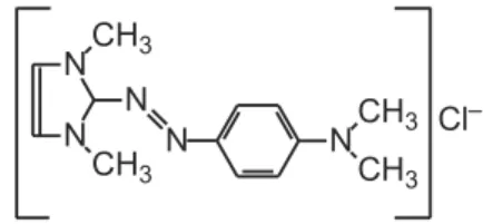
The basic red 51 dye, Figure 1, is a soluble dye widely used in several commercial formulations destined to
semi-permanent hair dyeing.44 They are used as temporarily
molecules deposited in the external structure of the hair by ionic forces involving interaction with protein ibers of the hair.45 The release of this kind of dyes in efluents is a
concern of legislations in several countries. Approximately 35% of women and 10% of men in Europe, Japan and the USA have used hair colorants and great part of these compounds and derivatives are released in the environment. The volume of efluents and the unknown details about toxicity and/or genotoxity of these compounds and their derivatives have attracted much attention. The contents of hair dyes in hair coloring formulations are restricted according to Annex III of the EU Cosmetic Directive. In addition, the use of certain substances has been banned in these formulations according to Annex II of the Directive because of their toxicity and/or carcinogenicity. Therefore, eficient treatment methods of efluents containing these residues are scarce.
The aim of the present study is to investigate the
capability of W/WO3 semiconductor systems to degrade
a basic red 51 dye, used as a model pollutant of hair dye bearing azo groups as chromophore in photoeletrocatalytic system irradiated by both ultraviolet (280-400 nm) and visible (420-630 nm) light.
Experimental
Chemicals and materials
All reagents used in preparing the solutions were of analytical grade, using distilled water puriied through the Milli-Q system (18.2 MΩ cm-1 Millipore) in their
preparation. The hair dye basic red 51 was purchased from the company Arianor. Tungsten foil (Alfa Aeser, 0.25 mm thick, 99.95%) was used as the substrate for oxide ilm growth.
Preparation of W/WO3 thin ilm electrode
W/WO3 electrode was prepared by anodization of
tungsten foil (Alfa Aesar, 0.25 mm, 99.95%). This foil was laser cut to 2×2 cm in size and mechanically polished on SiC sandpaper of successively iner roughness (800, 1000, 1200, 1500 and 2000). After this treatment the foil was washed in ultrasonic bath for 5 min in acetone followed by
isopropanol, water, dried with N2 and immediately used.46
For the experiments we used an anodizing conventional electrochemical cell of two-electrode, the tungsten foil (2×2 cm) as working electrode and a Pt gauze as counter-electrode. A tungsten foil was immersed in NaF solution 0.15 mol L-1 as the supporting electrolyte, applying a
ramp potential of 0.2 V s-1 until it reached 60 V, which was
maintained for 2 h,28 using a power supply 60 V/2 A stabilized
Tectrol®. After anodizing, the electrode was carefully washed
by immersion in deionized water and dried under N2 low.
As inal treatment, the electrode was annealed at 450 °C for
30 min according to procedure described in the literature.46
Characterization of W/WO3 thin ilm electrode
The morphological analysis of W/WO3 surface was
performed by scanning electron microscope FE-SEM high resolution with the source of electrons by ield emission, JEOL, model JSM-7500-F; energy dispersive X-ray spectroscopy (EDX) and atomic force microscopy (AFM) (Digital Instruments-Veeco model MultiMode Nanoscope
IIIa). The scans in AFM were performed in contact mode
(N3Si4 probe of Veeco model NP) and tapping mode (silicon probe of Nanoworld model NCH). The surface was also characterized by X-ray powder diffraction (XRD)
with a Siemens D5000 diffractometer (CuKα radiation,
λ = 1.541 Å), using a curved graphite monochromator,
and a ix divergence slit of 1/8° in a Bragg-Brentano configuration. The electrode was electrochemically characterized by linear scan voltammetry using a reactor
and sodium sulfate 0.10 mol L-1 as supporting electrolyte.
The reactor was submitted to irradiation of 150 W Xe lamps (Oriel) operating under wavelength region 280-400 nm and 420-630 nm, corresponding to the ultraviolet and visible regions, respectively. The electrochemical reactor is composed of three electrodes system, containing a Pt gauze as counter-electrode, Ag/AgCl, KCl saturated as reference
electrode and W/WO3 as working electrode.
Photoelectrocatalytic study
30 mL. In one reactor side was inserted a quartz window of 4.0×2.5 cm positioned to receive direct light irradiation at controlled wavelength (ilter 66216: 280-400 nm and 66219: 420-530 nm Oriel). In the working electrode,
W/WO3 acted as photo anode and the system was completed
by a Pt gauze as counter-electrode. The system was stirred by low of compressed air. The photoelectrocatalytic oxidation
experiments were conducted for: 1.0×10⁻⁵ mol L-1 basic red
51 in 0.10 mol L-1 sodium sulfate pH 2.0, controlled current
density of J = 1.25 mA cm-2, light irradiation of 150 W
xenon lamp-free ozone Oriel model 6255, operating in the ultraviolet and visible regions, respectively. The color removal was analyzed in the form of rate lows of the dye chromophore group, registering through a spectrophotometer UV-Vis linear diode array Hewlett Packard, model 8453, interfaced to an UV-visible ChemStation program Software, Hewlett Packard model HP-854X. All measurements were performed using quartz cells of 1 cm optical path at a wavelength range of 200-800 nm. The degradation of organic matter during photoelectrocatalytic oxidation was monitored by determination of total organic carbon (TOC) analyzer on a total carbon and inorganic model TOC VCP-N Shimatzu coupled to an automatic injector ASI. A galvanostat AUTOLAB PGSTAT 302 Model controlled by the software GPES was used to apply controlled current density at the photoanode during photoelectrocatalytic oxidation experiments. All pH measurements were carried out on a Corning 555 pH meter.
Results and Discussion
Morphology of W/WO3 thin ilm electrode
Figure 2B shows FE-SEM images of W/WO3 ilms
grown by electrochemical anodizing process (2 h at 60 V) and that obtained for tungsten (substrate) (Curve A). The image observation (Figure 2B) revealed the roughness of
the surface due to particles of WO3 ilm on the surface of
W. The nanoporous sizes are around 100 nm, which are best seen in the image capture with increased resolution, as shown in Figure 2C.
In order to diagnose possible contamination in the
synthesis process of the ilm W/WO3, the prepared electrode
was analyzed by energy dispersive X-ray spectroscopy (EDX), revealing the relative intensity of characteristic peaks of oxygen and tungsten identiied on the surface. The samples are predominantly tungsten and oxygen, without traces of luorine, conirming the formation of
W/WO3 ilm without contaminants that could interfere
in the eficiency of the material applied as photoanode in photoelectrocatalytic process.
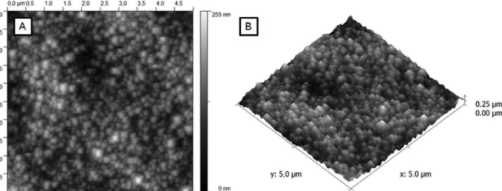
Figure 3 shows the topography in two-dimensional and
three-dimensional images of W/WO3 electrode surface by
AFM, in order to elucidate possible deformations on the electrode surface. It is possible to see the great uniformity
of WO3 in nanoporous form on the substrate surface
(tungsten), which is around 100 nm, also observed by FE-SEM analysis.
Figure 2. FE-SEM images of (A) W foil; (B) nanoporous W/WO3 thin
ilm electrode obtained by electrochemical anodization of tungsten foil in 0.15 mol L-1 NaF at 60 V for 2 h, annealed at 450 oC (30 min) and (C)
Figure 4 shows the X-ray diffraction patterns of tungsten
foil (Figure 4A) and W/WO3 samples obtained after 2 h at
60 V in 0.15 mol L-1 NaF, submitted to annealing at 450 oC
(30 min), Figure 4B. No diffraction peaks of WO3 appeared
on the substrate (Figure 4A), but the intensities of ive peaks
of WO3 on the sample prepared by anodizing process is seen
on: 2θ = 23.10, 2θ = 23.66, 2θ = 24.40, 2θ = 33.26 and
2θ = 34.10. This behavior is indicative of highly-crystalline
monoclinic structure of WO3 on the substrate surface. The
monoclinic phase has been reported to oxidize water and organic species under visible light.25,47,48
Photoactivity of W/WO3 thin ilm electrode
The photoactivity of the electrodewas tested recording
linear voltammetric curves (0.001 V s-1) immerging
W/WO3 photoanode in sodium sulfate 0.10 mol L-1, under
dark and irradiation of xenon lamp 150 W, operating in the ultraviolet (280-400 nm) and visible (420-630 nm)
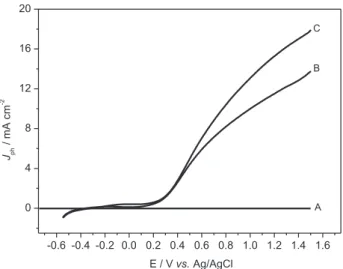
regions. The photocurrent vs. applied potential curves
obtained are shown in Figure 5. The photocurrent intensity is neglected at dark conditions (Curve A) and shows a marked increase of photocurrent at potential higher than 0.2 V under irradiation in the ultraviolet and visible regions, with maximum values of photocurrent (E = +1.5 V) around 14 mA cm-2 and 18 mA cm-2 for ultraviolet and
visible irradiation, respectively. At both conditions, there is photocurrent, indicating that photogenerated electrons (e−) and holes (h+)18 are formed by irradiation. Under
positive bias potential the current density drives the lacunas towards the surface of photoanode and the electrons to the
counter electrode (gauze Pt), which is not photoactive.49
This process reduces the recombination electron/hole, increases the lifetime of OH• radicals generated on the
surface of the photo anode due to water oxidation and produces high photocurrent. In both cases, the curves of
Iphvs. E increased when irradiated for either UV or visible
Figure 3. Atomic force microscopy images of W/WO3 thin ilm electrode obtained by anodization of tungsten foil in 0.15 mol L-1 NaF at 60 V for 2 h,
annealed at 450 °C (30 min). (A) - W foil, (B) - WO3 in nanoporous form.
Figure 4. X-ray diffraction images obtained for W foil (A) and
W/WO3 thin ilm electrode (B) obtained by anodization of tungsten foil
light. This means that ilm of W/WO3 structure can be
activated by light of longer wavelength (2.4 to 2.8 eV), 51
without decreasing water oxidation in visible region. This is
particularly important in view of the applications of a WO3
photoanode to the photodegradation of organic efluents since the solar light intensity strongly increases through the
400 ± 500 nm wavelength regions. The literature reports50
maximum photoactivity in the range 515-480 nm for ilms
with highly-crystalline monoclinic structure of WO3 with
a band gap between 2.41-2.58 eV. The red-shifting of the absorption bands is consistent with the characteristic values given for WO3 monoclinic structure.50,51 This behavior
suggests that the proposed method to obtaining ilms of
WO3 is a good strategy to increase the light absorption in
the long wavelength region above 480 nm.
The incident photon to electron conversion eficiency
(IPCE) was evaluated for WO3 irradiated on visible
and UV source. The IPCE (incident photon to current eficiency) calculated by; ICPE = (1240J / Pλ) × 100,
where J = photocurrent density (mA cm-2), P = light
power (mW cm-2) and λ = wavelength (nm), using current
values taken on potential of 1.5 V, vs. Ag/AgCl at pH 2.0
in 0.1 mol L-1 Na
2SO4) and values of irradiation monitored
at λ of 380 nm (ultraviolet) and 490 nm (visible). The
corresponding values of IPCE obtained were 106 ± 8.5% and 45 ± 2.1%, respectively. Note that values of IPCE higher than 100% are obtained and such values are consistent with
the ‘‘current-doubling’’ nature.52,53 These comparative
data can be diagnostic of the much better performance of
WO3 at higher wavelengths, but there is current doubling
effect. Irradiation of wavelengths smaller than 490 nm penetrates less into the ilm, these trends also translate
to a lower surface recombination for the photocarriers in
WO3. Therefore, better separation of electrons/roles in the
photoactivity is expected.
Photoelectrocatalytic oxidation of basic red 51
The photoelectrocatalytic oxidation of 1.0×10⁻⁵ mol L-1
basic red 51 dye solution was conducted in 0.10 mol L-1
Na2SO4 pH 2.0 under controlled current density of 1.25 mA
cm-2 with W/WO
3 photoanode irradiated by ultraviolet
(280-400 nm) and visible (420-630 nm) light. Figure 6 shows the UV-Vis spectra obtained before and after 120 min of photoelectrocatalytic oxidation for the system irradiated by ultraviolet or visible light. The original spectra obtained for basic red 51 hair dye exhibited two main bands: one assigned to the centers of the unsaturated aromatic molecule in the UV region (294 nm) and the other in the visible region (524 nm) due to the azo chromophore group (-N=N-).
The results indicate that the coloration of the dye solution is completely removed when treated by photoelectrocatalytic
Figure 5. Photocurrent/potential curves obtained for W/WO3 thin ilm
electrode in Na2SO4 0.1 mol L-1, without (A) and under visible (C) and
ultraviolet irradiation (B). ν = 0.001 V s-1.
Figure 6. UV-visible spectra obtained for 1.0×10⁻⁵ mol L-1 basic red 51
dye before (i) and after 120 min (ii) of photoelectrocatalytic oxidation in:
sodium sulfate pH 2.0, current density 1.25 mA cm-2, under ultraviolet
oxidation using both systems of irradiation. The removal of all bands in the UV region was also observed. The photoelectrocatalytic decomposition of the basic red 51 dye in 0.1 mol L-1 Na
2SO4 pH 2 was followed by measuring
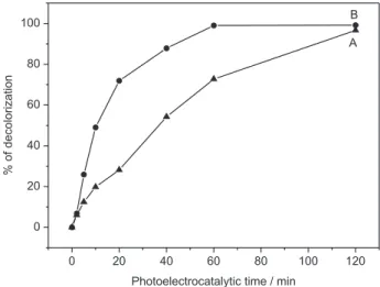
the degradation in 524 nm (Figure 7A). Although both systems present total color removal after 120 min, 100% discoloration was observed after 60 min of treatment of 1.0×10⁻⁵ mol L-1 basic red for W/WO
3 photoanode
irradiated by visible light, Figure 7B, while only 70% was obtained under irradiation of ultraviolet region, Figure 7A.
These results explain the higher photoactivity for W/WO3
photoexcited with visible irradiation.
Graphs of absorbance reduction as a function of time was plotted as ln [A]t/[A] vs. t following discoloration at
524 nm. All curves obtained showed linear relationship up to 120 min of photoelectrocatalysis for dye degradation under irradiation at UV region and visible region, which is a typical behavior of a pseudo irst order reaction in dye consumption. The constant discoloration rates obtained were
−0.031 min-1 and −0.064 min-1. The higher discoloration
rate observed for W/WO3 when irradiated at wavelenght of
420-630 nm was interesting and can be explained by other
phenomenon occurring on electrode surface.54 Conventional
nano-dimensional semiconductor photocatalysts degrade organic pollutants through a series of charge transfers,
according to: i) reaction between the photogenerated hole
and water to produce the potent oxidant agent, hydroxyl radical OH• as shown in equations 1 and 2:55,56
WO3 + hv→ WO3−e-BC + WO3−h+BV (1)
WO3−h+BV + H2Oads→ WO3−OH•ads + H+ (2)
ii) reaction between the lacunas and adsorbed pollutant
on catalyst surface:
Pads + WO3−h+BV→ P• + H+ (3)
However, the mechanism occurring in equation 2 is more accepted in the literature due to the reduced longevity generated role in photoanode surface, in the photoseconds order with the photoelectrocatalytic oxidation of the basic red 51 over hydroxyl radicals.
Nevertheless, the higher eficiency observed for dye
degradation when W/WO3 electrode is photoexcited
with visible radication can be explained due to other phenomenon taking place in the mechanism. The chemistry of tungsten oxide reveals a second potential mechanism for
pollutant degradation WO3, when they can present in mixed
oxidation states and can also act as an oxidizing agent, as shown in equation 4:
e−+ H+ + WO
3→ HxW6+(1-x) W5+xO3 (4)
The reduction of W6+ to W5+ occurs due to absorption of
light with energies in the range 2.4-2.8 eV,57 as diagnosed
by their electrochromic properties. The adsorption of dye on electrode surface and the oxidizing power of HxW6+(1-x) W5+xO3 are analogous to the description given
for methanol oxidation and methylene blue treated by
photoelectrochemistry on WO3 electrodes.54 This could be
amplifying to the effect expected for a system operating
under OH• generation on W/WO
3 surface.
In order to test the mineralization degree obtained after 120 min of treatment by photoelectrocatalytic oxidation of hair dye (1.0×10⁻⁵ mol L-1) in Na
2SO4 (0.1 mol L-1) at
pH 2.0 the TOC removal was measured in both solution. Only 40% of the total organic carbon (TOC) removal was observed on system activated by UV irradiation and 63% on system irradiated by visible light. This behavior indicates that photoelectrocatalysis technique would be a good option not only to decolorize the solution but also to mineralize the organic material. Besides, there is a signiicant gain on irradiation by visible light on electrode surface during dye treatment. This effect provides an opportunity for the sustainable solar assisted remediation of organic contaminated water bodies for hair dyes.
Conclusions
Our indings indicate that W/WO3 thin ilms can be
grown by electrochemical anodization on W foil and it is the base to form photoanodes with uniform nanoparticles
of 100 nm. The best conditions to form crystalline W/WO3
Figure 7. Discoloration percentage, λmax = 524 nm, of 1.0×10⁻⁵ mol L-1
dye basic red 51, 0.10 mol L-1 in Na
2SO4, pH 2.0. Photoelectrocatalytical
oxidation conditions: Current density of 1.25 mA cm-2, Irradiation
ilms were obtained during anodization in 0.15 mol L-1 NaF
electrolyte at 60 V during 2 h. The photoanode presents good photoactivity when illuminated by both region wavelenght from 280-400 nm (UV light) and visible region 420-630 nm. The photoanode was tested in removal of basic red 51, widely used as dye in temporary and semi-permanent hair dyeing. It is possible to get 100% discoloration of 1.0×10⁻⁵ mol L-1
dye solution, after 60 min when treated using irradiation under visible region, and after 120 min of treatment under irradiation in ultraviolet region. The discoloration follows a kinetics of pseudo-irst order with constant rate of k = −0.064
and −0.031 min-1 for both systems, respectively. The TOC
removal obtained for both systems were 63% and 40%, respectively, indicating that the process is more eficient
when operating under visible irradiation of the W/WO3
photoanode. The phenomenon can be explained due to electrochromic properties of the WO3 that can act as an
oxidizing agent, when irradiated by visible light. The process can be an effective alternative to treat efluents containing hair dyes residues mainly from basic dye family. Further studies are in progress to test the risk of forming by-products.
Acknowledgments
The authors thank FAPESP, CNPq and CAPES for the inancial support of this work.
References
1. Hepel, M.; Luo, J.; Electrochim. Acta2001, 47, 729.
2. Yu, J.; Qi, L.; Cheng, B.; Zhao, X.; J. Hazard. Mater.2008,
160, 621.
3. Rajeshwar, K.; Tacconi, N. R. In Interfacial Electrochemistry. Theory, Experiment and Applications; Wieckowski, A. ed.,
Marcel Dekker: New York, 1999, pp. 721-736.
4. Zanoni, M. V. B.; Sene, J. J.; Anderson, M. A.; J. Photochem. Photobiol., A2003, 157, 55.
5. Carneiro, P. A.; Osugi, M. E.; Sene, J. J.; Anderson, M. A.; Zanoni, M. V. B.; Electrochim. Acta2004, 49, 3807.
6. Osugi, M. E.; Umbuzeiro, G. A.; Anderson, M. A.; Zanoni, M. V. B.; Electrochim. Acta2005, 50, 5261.
7. Osugi, M. E.; Umbuzeiro, G. A.; Castro, F. J. V.; Zanoni, M. V. B.; J. Hazard. Mater. 2006, 137, 871.
8. Osugi, M. E.; Rajeshwar, K.; Ferraz, E. R. A.; Oliveira, D. P.; Araújo, A. R.; Zanoni, M. V. B.; Electrochim. Acta2009, 54, 2086.
9. Oliveira, A. P.; Carneiro, P. A.; Sakagami, M. K.; Zanoni; M. V. B.; Umbuzeiro, G. A.; Mutat. Res.2007, 626, 135.
10. Fraga, L. E.; Anderson, M. A.; Beatriz, M. L. P. M. A.; Paschoal, F. M. M.; Romão, L. P.; Zanoni, M. V. B.; Electrochim. Acta 2009, 54, 2069.
11. Cruz, A. M.; Martínez, D. S.; Cuéllar, E. L.; Solid State Sci.
2010, 12, 88.
12. Yu, J.; Qi, L.; J. Hazard. Mater. 2009, 169, 221.
13. Hong, X. T.; Wang, Z. P.; Cai, W. M.; Lu, F.; Zhang, J.; Yang, Y. Z.; Ma, N.; Liu, Y. J.; Chem. Mater. 2005, 17, 1548. 14. Yu, J. C.; Yu, J. G.; Ho, W. K.; Jiang, Z. T.; Zhang, L. Z.; Chem.
Mater. 2002, 14, 3808.
15. Sayama, K.; Hayashi, H.; Arai, T.; Yanagida, M.; Gunji, T.; Sugihara, H.; Appl. Catal., B2010, 94, 150.
16. Hong, S. J.; Jun, H., Borse, P. H.; Lee, J. S.; Int. J. Hydrogen Energy2009, 34, 3234.
17. Marsen, B.; Miller, E. L.; Paluselli, D.; Rocheleau, R. E.; Int. J. Hydrogen Energy2007, 32, 3110.
18. Somasundaram, S.; Chenthamarakshan, R.; Tacconi, N. R.; Basit, N. A., Rajeshwar, K.; Electrochem. Commun. 2006, 8, 539.
19. Colton, R. J.; Guzman, A. M.; Rabalais, J. W.; J. Appl. Phys. 1978, 49, 409.
20. Yous, B.; Robin, S.; Donnadieu, A.; Dufour, G.; Maillot, C.; Roulet, H.; Senemaud, C.; Mater. Res. Bull. 1984, 19, 1349.
21. Sivakumar, R.; Moses, Ezhil Raj, A.; Subramanian, B.; Jayachandran, M.; Trivedi, D. C.; Sanjeeviraja, C.; Mater. Res. Bull. 2004, 39, 1479.
22. Santato, C.; Odziemkowski, M.; Ulmann, M.; Augustynski, J.;
J. Am. Chem. Soc. 2001, 123, 10639.
23. Wang, H.; Lindgren, T.; He, J.; Hagfeldt, A.; Lindquist, S. E.;
J. Phys. Chem. B2006, 104, 5686.
24. Santato, C.; Ulmann, M.; Augustynski, J.; Adv. Mater. 2001, 13, 511.
25. Santato, C.; Augustynski, M. J.; J. Phys. Chem. B2001, 105,
936.
26. Yamanaka, K.; Oakamoto, H.; Kidou, H.; Kudo, T.; Jpn. J. Appl. Phys. Part 1, Regul. Pap. Short Notes Rev. Pap. 1986, 25, 1420. 27. Bellac, D. L.; Azens, A.; Granqvist, C. G.; Appl. Phys. Lett.
1995, 66, 1715.
28. Watcharenwong, A.; Chanmane, W.; Tacconi, N. R.; Chenthamarakshan, C. R.; Kajitvichyanukul, P.; Rajeshwar, K.; J. Electroanal. Chem. 2008, 612, 112.
29. Yang, B.; Li, H.; Blackford, M.; Luca, V.; Curr. Appl. Phys.
2006, 6, 436.
30. Baeck, H.; Choi, K.-S.; Jaramillo, T.F.; Stucky, G.D.; McFarland, E.W.; Adv. Mater. 2003, 15, 1269.
31. Shen, P. K.; Tseung, A. C. C.; J. Mater. Chem. 1992, 2, 1141. 32. Yagi, M.; Sone, K.;Yamada, M.; Umemiya, S.; Chem. Eur. J.
2005, 11, 767.
33. Yagi, M.; Umemiya, S.; J. Phys. Chem. B2002, 106, 6355.
34. Sone, K.; Konishi, K.; Yagi, M.; Chem. Eur. J.2006, 12, 8558. 35. Shen, P. K.; Tseung, A. C. C.; J. Electrochem. Soc. 1994, 141,
3082.
37. Shen, P. K.; Chen, K. Y.; Tseung, A. C. C.; J. Electroanal. Chem.
1995, 389, 223.
38. Bock, C.; MacDougall, B.; Electrochim. Acta2002, 47, 3361. 39. Waldner, G.; Bruger, A.; Gaikwad, N. S.; Neumann-Spallart,
M.; Chemosphere2007, 67, 779.
40. Luo, J.; Hepel, M.; Electrochim. Acta2001, 46, 2913.
41. Hepel, M.; Hazelton, S.; Electrochim. Acta2005, 50, 5278. 42. Lina, C-F.; Wub, C-H.; Onna, Z-N.; J. Hazard. Mater.2008,
154, 1033.
43. Georgieva, J.; Armyanov, S.; Valova, E.; Tsacheva, Ts.; Poulios, I.; Sotiropoulos, S.; J. Electroanal. Chem.2005, 585, 35. 44. Masukawa, Y.; J. Chromatogr., A2006, 1108, 140.
45. Robbins, C. R.; Chemical and Physical Behavior of Human Hair, 4th ed. Spring Verlag: New York, 2002.
46. de Tacconi, N. R.; Chenthamarakshan, C. R.; Yogeeswaran, G.; Watcharenwong, A.; de Zoysa, R. S.; Basit, N. A.; Rajeshwar, K.; J. Phys. Chem. B2006, 110, 25347.
47. Abe, R.; Takami, H.; Murakami, N.; Ohtani, B.; J.Am. Chem. Soc.2008, 130, 7780.
48. Solarska, R.; Santato, C.; Jorand-Sartoretti, C.; Ulmann, M.; Augustynski, J.; J. Appl. Electrochem. 2005, 35, 715. 49. Tsuchiya, H.; Macak, J. M.; Muller, L.; Kunze, J.; Muller, F.;
Greil, P.; Virtanen, S.; Schmuki, P.; J. Biomed. Mater. Res.A 2006, 77, 534.
50. Bamwenda, G. R.; Arakawa H.; Appl. Catal. A2001, 210, 181. 51. Granqvist, C. G.; Sol. Energy Mater. Sol. Cells2000, 60, 201.
52. Morrison, S. R.; Freund, T.; J. Chem. Phys. 1967, 47, 1543. 53. Gomes, W. P.; Freund, T.; Morrison, S. R.; J. Electrochem. Soc.
1968, 115, 818.
54. Macphee, D. E.; Rosemberg, D.; Skellern, M. G.; Wells, R. P.; Duffy, J. A.; Killham, K. S.; J. Solid State Electrochem. DOI 10.1007/s10008-010-1062-4. Published online on 20 April 2010.
55. Martin, S. T.; Herrmann, H.; Choi, W.; Hoffmann, M. R.; Trans. Faraday Soc. 1994, 9l, 3315.
56. Hoffman, M. R.; Martin, S. T.; Choi, W.; Bahnemann, D. W.;
Chem. Rev. 1995, 95, 69.
57. Finley, H. O.; Semiconductor Electrodes, Elsevier: Amsterdam,
1988, p. 519.
Submitted: July 28, 2010
Published online: January 18, 2011