Abstract
In this paper, squeeze film damping in a micro-beam resonator based on micro-polar theory has been investigated. The proposed model for this study consists of a clamped-clamped micro-beam bounded between two fixed layers. The gap between the micro-beam and layers is filled with air. As fluid behaves differently in micro scale than macro, the micro-scale fluid field in the gap has been modeled based on micro-polar theory. Equation of motion governing transverse deflection of the micro- beam based on modi-fied couple stress theory and also non-linear Reynolds equation of the fluid field based on micropolar theory have been non-dimensionalized, linearized and solved simultaneously in order to calculate the quality factor ofthe resonator. The effect of micropo-lar parameters of air on the quality factor has been investigated. The quality factor of the of the micro-beam resonator for different values of non-dimensionalized length scale of the beam, squeeze number and also non-dimensionalized pressure has been calculated and compared to the obtained values of quality factor based on classical theory.
Keywords
MEMS, Micro-polar theory, Squeeze film damping
Study of Squeeze Film Damping in a Micro-beam
Resonator Based on Micro-polar Theory
1 INTRODUCTION
Recently, progress in technology of micro-electromechanical systems (MEMS) can be seen in fa-bricating new devices and creating innovative applications. The fact that these systems can be produced at low cost and in large volumes, also in small size and with low-energy consumption, make them attractive and cause a great interest among scientists and engineers. Variety of MEMS devices such as accelerometers, micro-pumps, micro-sensors and micro-resonators, have been utilized in engineering, medical and science applications. But unfortunately because of com-plex design process of MEMS devices, they are still being designed applying trial and error
met-Mina Ghanbari a Siamak Hossainpour a* Ghader Rezazadeh b
a Mech. Eng. Dept., Sahand University of
Technology, Tabriz, Iran
b Mech Eng. Dept., Faculty of Eng.,
Urmia University, Urmia, Iran
*Author's email: [email protected]
http://dx.doi.org/10.1590/1679-78251364
Latin American Journal of Solids and Structures 12 (2015) 77-91
hod because of inherent couple-energy domains as electrostatic, thermal and mechanical forces involved in designe process. Most typical MEMS devices employ a capacitor that consists of two parallel plates in which one plate is actuated electrically and its motion is detected by capacitive changes. In order to increase the efficiency of actuation, the distance between parallel plates is minimized. Under these conditions the so-called squeeze film damping is pronounced (Nayfeh and Younis, 2004; Younis, 2004).
Latin American Journal of Solids and Structures 12 (2015) 77-91
Although several studies have been done on the dynamic behavior of the micro-structures un-der squeeze film damping but most of them have used the linearized Reynolds equation obtained by classical theories, for simulating the fluid field. Numerous experimental results indicate that, as fluid flow moves differently in the micro-scale than that in the macro scale, in the study of micro and nano-scale fluid mechanics, the Navier-Stokes equations derived from classical conti-nuum, become incapable of explaining the micro scale fluid behaviour (Kucaba-Pietal, 2004).
A novel approach that was developed by Eringen (1966, 1972) includes the effect of local ro-tary inertia and couple stresses and offers mathematical foundation to capture the motions of the micro-scale fluids. Todays, researches show that applying micro-polar fluid theory in modeling the micro-scale fluid field can be a useful method for predicting the behaviour of the micro- scale flow [Srinivasacharya et al ,2001; Kucaba-Pietal, 2008; Deo and Shukla, 2012].
In this paper, free vibration of the micro-beam under the effect of squeeze film damping ba-sed on micro-polar theory is studied. The coupled governing equations of motion of the beam based on modified couple stress theory and pressure field of the fluid based on micro-polar theory are solved simultaneously using Galerkin based reduced order model. The effect of non-dimensionalized length scale and also coupling parameter of air on the of quality factor of the resonator is studied. Values of the guality factor of the micro-beam for different values of length to width ratio of the beam and also different values of aqueeze number amd non-dimensionalized pressure are determined and compared to those obtained based on classical theory.
2 COSSERAT (MICRO-POLAR) THEORY
The Cosserat theory of elasticity incorporates a local rotation of points as well as the translation assumed in classical elasticity; also it included a couple stress as well as the stress. Several authors developed the theory in the language of modern continuum mechanics as Mindlin and Tiersten (1962), Mindlin (1965), Eringen (1868) and Nowacki (1970). The Micro-inertia which was incorporated by Eringen and Cosserat elasticity was renamed micro-polar elasticity. Eringen (1968) introduced the concept of micro-polar fluids to characterize concentrated suspensions of neutrally buoyant rigid particles in a viscous fluid where individuality of substructures affects the physical outcome of the flow. Basically, these fluids support couple stresses and body couples furthermore, they exhibit rotational and inertial effects. It may be noted that micro-polar fluid theory takes care of the rotation of fluid particles by means of a kinematic vector ca-lled the micro-rotation vector which is independent from the vorticity of the fluid and is absent in classical continuum.
2.1 Kinematics
Latin American Journal of Solids and Structures 12 (2015) 77-91
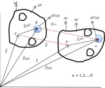
Figure 1:Deformation of a micro-volume.
x⃗⃗ = X⃗⃗⃗ + U⃗⃗⃗ (1)
⃗⃗⃗ � = ⃗⃗⃗ + �⃗⃗�� ; � = −� = − � (2)
Where �⃗⃗�is the position of a point in the microelement relative to the mass center of ∆V and
� is defined as skew-symmetric micro-rotation tensor which is independent of macro-rotation in the micro-polar theory. By introducing � as macro- deformation and � and � as micro-deformation tensors, the macro and micro strain tensors are defined as:
C ≈ U , + U , + ; E ≡ C − = (U , + U , ) (3)
Ψ ≈ U , + + ϕ ; £ ≡ Ψ − = E + R − ϕ (4)
� ≈ � , ; � ≡ − � , (5)
Where � is defined as the macro-strain tensor while £ and � are defined as micro-strain tensors, respectively.
2.2 Balance Equations
As shown in figure 2, it is assumed that the transfer of the interaction between two particles of the body through a surface element ds occurs not only by means of a traction vector but also a moment vector ds. Surface forces and couples are then represented by the generally skew-symmetric stress � and couple stress tensors:
Latin American Journal of Solids and Structures 12 (2015) 77-91 Figure 2: surface and body loads on the macro-volume.
So, the equations of the balance of momentum and balance of moment of momentum are as:
� . + = = , , (7)
, + − = � = , , (8)
In which and are body forces and body couples, respectively, is mass density, is micro-inertia density, are micro-displacements and � are micro-rotations.
2.3 Constitutive Equations
The constitutive equations of the micro-polar media link the deformation and micro-rotations tensors to the force and couple stresses as:
= � + μ + k � + k � − � (9)
= � + � + � (10)
There are 4 extra modulus in micro-polar theory , , and k .If these modulus are set equal to zero, the classic continuum media is obtained.
3 MODEL DESCRIPTION AND ASSUMPTIONS
Latin American Journal of Solids and Structures 12 (2015) 77-91
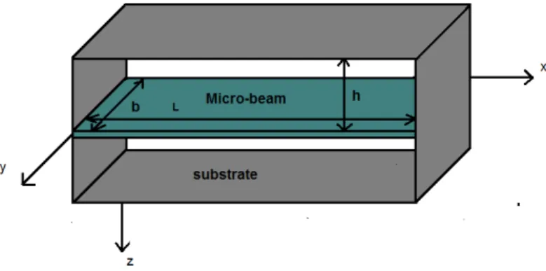
Figure 3: Shematic of proposed model for studying squeeze film damping.
By adding a term representing the force acting on the micro-beam owing to the pressure of the squeeze gas film, the equation of motion governing the transverse deflection of the beam is as follow (Li et al., 2007; Asghar et al., 2010; Arbind et al., 2014, Sedighi et al, 2014)
EI q ∂ , + ρbh ∂ , + [EbhL ∫ ( )
b
] ×∂∂
= − ∫ , , − p
(11)
Where � = � + ℎ , , are the position along the length and width of the
micro-beam. , is the defletion of the micro-beam at the position and the time . , , ℎ , , G and are the length, width, thickness , density , shear modulus and the length scale parameter of the micro-beam material, respectively. , , is the absolute pressure in the gap at the posi-tion , and and the time and is the ambient pressure. The boundary conditions of the mi-cro-beam are::
, = , = , = , = (12)
The pressure , , is governed by the non linear Reynolds equation of the compressible micro-polar fluid as: (Naduvinamani and Mrali, 2007)
{[ ℎ + ℎ − ℎ ℎ ℎ ] } + {[ ℎ + ℎ − ℎ ℎ ℎ ] }
= � ℎ + ℎ
(13)
Latin American Journal of Solids and Structures 12 (2015) 77-91
distinguish it from a Newtonian fluid. In the limiting case of → , Equation (13) reduces to the Reynolds equation of a Newtonian fluid. Boundary conditions of equation (13) are:
, , = , , = , , = , , = (14)
By considering the following non-dimensional variables:
= , = , = , = , � = , = , =ℎ = − (15)
where is the initial gap, = √� ℎ�� 4
� = , = . , =
2 2√
�� �
� ℎ is the first natural frequency
of the clamped-clamped micro-beam, the Equations (11) and (13) are rewritten in the non-dimensional form as:
+ + [∫ ( ) ] × = − � ∫ � −
{[ + − ℎ ( ) ] � �}
(16)
+ {[ + − ℎ ] � �} = � (� + �) (17)
where = � ℎ 02
�� � =
4
�� � 0 , = is the aspect ratio of the cross section of the micro-beam
and � = 2
02 is the squeeze number which represents a measurement of the compressibility of
the fluid in the gap. For higher values of σ due to higher oscillation frequencies, the fluid is trap-ped in the gap and acts like a spring. For lower values of σ due to lower oscillation frequencies the fluid is nearly incompressible. The corresponding non-dimensional boundary conditions of Equations (16) and (17) are:
, = , = , , = , = (18)
� , , = � , , = , � , , = � , , = (19)
Due to non-linearity of Equation (17), solving this equation requires linearizing. As mentioned above, due to small oscillation of the micro-beam, the variation of the pressure from the ambient pressure in every point in the domain is also small. � , , is given by :
Latin American Journal of Solids and Structures 12 (2015) 77-91
Substituting Equation (20) into Equation (17) and linearizing it around , the following equa-tion is obtained:
{[ − ℎ ] � + [ − ℎ ] � } = � { � − } (21)
With the following boundary conditions:
� , , = � , , = , � , , = � , , = (22)
It should be noted that, for vibration amplitude of approximate less than 0.5 , the values of non-linear term that are dropped in linearizing process of the Reynolds equation is less than 10 % of the linear terms. So we can claim that our linearizing process is valid for vibration amplitude of approximate less than 0.5 .
4 NUMERICAL SOLUTIONS
In the field of numerical analysis, Galerkin method is a means for converting a partial differential equation to a problem of linear or nonlinear system of ordinary differential equations, which may then be projected to a lower dimensional system. It relies on the weak formulation of an equation and works in principle by restricting the possible solutions as well as the test functions to a sma-ller space than the original one. These small systems are easier to solve than the original problem, but their solution is only an approximation to the original solution. In Galerkin method unknown function is expressed as a linear combination of a set of prescribed basis or shape functions. The overall quality of a Galerkin approximation depends on number and type of the shape functions. In this work a Galerkin based reduced order model are applied to solve the squeeze film damping coupled equations (16) and (21).
In this work, we seek approximate solutions for , and � , , in the form of:
, ≅ ∑
=
(23)
� , , ≅ ∑ ∑ � �
= =
(24)
where we approximated the deflection and pressure changes of the system with linear combina-tions of finite number of suitable shape funccombina-tions.
Substituting Equations (23) and (24) into Equations (16) and (21) leads to the following equa-tions:
( , ) = ∑ +
=
∑ І�
=
− ∑ ІІ ∫ ІІ
=
Latin American Journal of Solids and Structures 12 (2015) 77-91
+ � ∑ ∑ �
= =
∫ �
ℑ(� , , ) = [ + − NLcoth ( ) ] ∑ ∑ �′′ �
= =
+ [ + − NLcoth ( ) ] ∑ ∑ � �′′
= = − � ∑ ∑ � � = = +� ∑ = (26)
By using the Galerkin method, following reduced order models can be obtained:
∑
=
+ ∑
=
+ D ∑ ∑ � �
= =
= f = , … r (27)
D ∑ ∑
= =
+ D ∑ ∑
= =
− D ∑ ∑ � �
= =
+ D ∑ � �
=
=
q = , … n , g = , … m
(28)
With the following coefficients:
= ∫ , = ∫ І� − ∫ [ ІІ ∫ ІІ ] ,
� = ∫ � , � = ∫ � , = ∫ � �′′ ,
= ∫ � � , = ∫ � � , = ∫ � �′′ ,
� = ∫ � � , � = ∫ � , � = ∫ �
(29)
D = p , D = ( + L − NLcoth (NL)) , D = σ (30)
Applying proper shape functions in Equations.(23) and (24) which satisfy the accompanying boundary conditions (18) and (22) and integrating the coupled Equations (27) and (28) simulta-neously, in which = ̅ ωk� and = ̅ ω � , the complex frequencies for the first mode
vibration of the beam are achieved. Shape functions are considered as following:
Latin American Journal of Solids and Structures 12 (2015) 77-91
So, According to complex frequency approach, quality factor can be calculated as:
= |� ω |
5 NUMERICAL RESULTS
The material properties of the micro-beam resonator studied in this paper are given in table 1
Param eters V alues
Density (kg/m
Young's modulus (G�a
Shear modulus (G�a
Length μm
Width μm
Thickness μm
Initial gap (μm .
Table 1: The material and geometrical properties of the micro-beam resonator.
For the micro-beam with mentioned properties, the numerically obtained values of quality factor exhibit good convergence when r value is taken as 6. The converged results for a cantilever micro-beam resonator based on classical theory are validated with the analytical, numerical and experi-mental results available in open literature. For design properties that are used for the experimen-tal study by Pandey and Pratap (2007) the obtained results in this work are in good agreement with the analytical, numerical and experimental results. Table 2 shows comparison of damping ratio obtained by different methods.
Experimental (Pandey and Pratap 2007)
FE model (Pandey and Pratap 2007)
Analytical (Pandey and Pratap 2007)
FE model (Chaterjee and
Pohit 2009)
Semi-analytical model (Chaterjee
and Pohit 2010)
This work
. ± . . . .
Table 2: Comparison of damping ratio (� obtained by different experimental and analytical methods.
Latin American Journal of Solids and Structures 12 (2015) 77-91
of air are obtained and shown in figure 4. Assuming the values of micro-polar parameters of water obtained experimentally in (Kucaba-Pietal, 2008), we can consider coupling parameter of air being in the range of ≤ ≤ . Results show that the values of quality factor decreases by increasing the values of and .
Figure 4: Calculated quality factor for different values of micro-polar parameters of air.
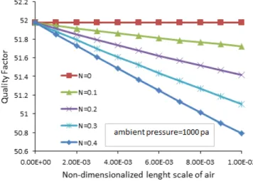
Then, the values of quality factor versus different values of non-dimension length scale of the
micro-beam and coupling parameter of air for = and = . are obtained and shown
in figure 5. Results show that higher values of non-dimensionalized length scale of the micro-beam and lower values of coupling parameter of air result in higher values of quality factor.
Figure 5: Calculated quality factors versus non-dimensional length scale parameter of the micro-beam for different values of coupling parameter of air.
Latin American Journal of Solids and Structures 12 (2015) 77-91
increasing , the difference between the obtained values of the quality factor increases. Results also show that the minimum difference is observed in the case of the classic micro-beam.
Figure 6: Difference between the obtained values of quality factor based on classic and micro-polar theory.
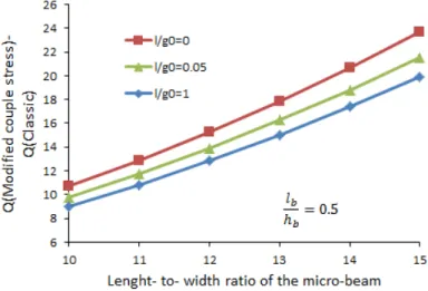
Quality factor of the micro-beam based on classic and modified couple stress theory versus diffe-rent values of = arecalculated and shown in Fig.7. Results show that higher values of results in higher differences. Furthermore it can be observed that the maximum differences occur in the case of the classic fluid field.
Figure 7: Difference between the obtained values of quality factor based on classic and modified couple stress theory
Latin American Journal of Solids and Structures 12 (2015) 77-91
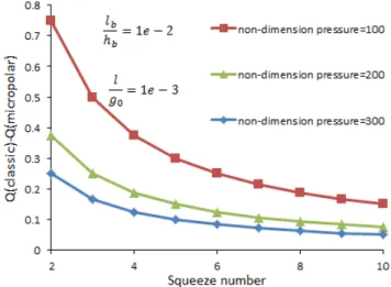
8. It can be noticed that the maximum differences are observed in lower values of squeeze number and non-dimension pressure.
Figure 8: Difference between the obtained valuesof quality factor based on classic and micro-polar theory versus different values of squeeze number
4 CONCLUSIONS
In this paper, squeeze film damping in the micro-beam resonator was studied. Governing equa-tions of motion for the micro-beam and fluid field respectively based on modified couple stress theory and micropolar theory were solved simultaneously applying Galerkin discretization and complex frequency approach. By considering coupling parameter of air being in the range of ≪
Latin American Journal of Solids and Structures 12 (2015) 77-91
References
Nayfeh, H., Younis, M. I. (2004). A new approach to the modeling and simulation of flexible microstructures under the effect of squeeze-film damping, Journal of Micromechanics and Microengineering 14: 170–181.
Younis, M. I. (2004). Modeling and simulation of microelectromechanical systems in multi-physics field, Ph.D. Thesis, Virginia Polytechnic Institute and State University, United States.
Newell, W. E. (1968). Miniaturization of tuning forks, Science 161: 1320–1326.
Zook, J. D., Burns, D. W., Guckel, H., Sniegowski, J. J., Engelstad, R. L and Feng. Z. (1992). Characteristics of polysilicon resonant microbeams, Sensors and Actuators 35: 290–294.
Christian, R. G. (1966). The theory of oscillating-vane vacuum gauges, Vacuum 16: 175–178.
Legtenberg, R., Tilmans, H. A. (1994). Electrostatically driven vacuum-encapsulated polysilicon resonators. Part I. Design and fabrication, Sensors and Actuators 45: 57–66.
Starr, J. B. (1994). Squeeze-film damping in solid-state accelerometers, in Proceeding. IEEE Solid-State Sensors and Actuators Workshop: 44–47.
Blech, J. J. (1983). On isothermal squeeze films, Journal of Lubrication. Technology 105: pp. 615–620.
Kadar, Z., Kindt, W., Bossche, A., Mollinger, J. (1996). Quality factor of torsional resonators in the low-pressure region, Sens. Actuators 53: 299–303.
Li, B., Wu, H., Zhu, C., Liu, J. (1999). The theoretical analysis on damping characteristics of resonant microbeam in vacuum, Sensors and Actuators 77: 191–194.
Bao, M., Yang, H., Yin, H., Sun, Y. (2002). Energy transfer model for squeeze-film air damping in low vacuum, Journal of Micromechanics and Microengineering 12: 341–346.
Yang, Y. J., Gretillat, M. A., Senturia, S. D. (1997). Effect of air damping on the dynamics of nonuniform defor-mations of microstructures, in 1997 IEEE. International Conference of Solid State Sensors and Actuators 2:1093– 1096.
Hung, E. S., Senturia, S. D. (1999). Generating efficient dynamical models for microelectromechanical systems from a few finite-element simulations runs, Journal of Microelectromechal Systems 8: 280–289. Pandey, A. K., and Pratap, R. (2007). Effect of flexural modes on squeeze film damping in MEMS cantilever resonators, Journal of Micromechanics and Microengineering 17: 2475-2484.
Younis, M. I., Nayfeh, A. H. (2007). Simulation of squeeze-film damping of microplates actuated by large electros-tatic load, ASME. Journal of Computational and Nonlinear Dynamics 2: 101-112.
Chatrejee, S., Pohit, G. (2009). A large deflection model for the pull-in analysis of electrostatically actuated micro cantilever beams, Journal of Sound and Vibration 322: 969-986.
Chatrejee, S., Pohit, G. (2010). Squeeze- film characteristics of cantilever micro-resonators for higher modes of flexural vibration, International Journal of Engineering. Science and Technologhy 2: 187-199.
Khatami, F., Rezazadeh, G. (2009). Dynamic response of a torsional micromirror to electrostatic force and me-chanical shock, Microsystem Technologies 15: 535–545.
Kucaba-Pietal, A., 2004, Microchannels flow modelling with the micropolar fluid theory, Bulletin of the Polish Academy of Science Technical science 52: 209-213
Eringen, A.C. (1966). Theory of micro-polar fluids, Journal of Applied Mathematics and Mechanics 16: 1-18. Eringen, A. C. (1972). Theory of thermo micro-polar fluids, Journal of Mathematic Analyses and Applications 38: 480-496.
Srinivasacharya, D., Ramana Murthy, J. V., Venugopalam, D. (2001). Unsteady stokes flow of Micropolarfluid between two parallel porous plates, International Journal of Engineering Science 39: 1557–1563.
Latin American Journal of Solids and Structures 12 (2015) 77-91 Deo, S., Shukla, P. (2012). Creeping flow of micro-polar fluid past a fluid sphere with non-zero spin boundary conditions, International Journal of Engineering Technologhy 2: 67-76.
Cosserat, E., Cosserat, F. (1909). Theory of deformable bodies, Hermann, Paris.
Mindlin, R. D., Tiersten, H. F. (1962). Effect of couple stresses in linear elasticity, Archive for Rational Mechanics and analysis 11: 415-448.
Mindlin, R. D. (1965). Stress functions for a cosserat continuum," International Journal of Solids and Structures 1: 265-271.
Eringen, A. C. (1968). Theory of micropolar elasticity," in Fracture 1: 621-729.
Li, P., Hu, R., Fang, Y. (2007). A new model for squeeze-film damping of electrically actuated microbeams under the effect of a static deflection, Journal of Micromechanics and Microengineering 17: 1242-1251.
Asghari, M., Rahaeifard, M., Kahrobaiyan, M.H., Ahmadian, M. T. (2010). The modified couple stress functiona-lly graded Timoshenko beam formulation, Materials and Design 31: 2324-2329.
Arbind, A., Reddy, J. N and Srinivasa, A. R. (2014). Modified couple stress-based third-order theory for nonlinear analysis of functionally grades beams, Latin American Journal of Solids and Structures 11: 459-487.
Sedighi, H. M., Changizian, M and Noghrehabadi, A. (2014). Dynamic pull-in instability of geometrically nonlinear actuated micro-beams based on the modified couple stress theory, Latin American Journal of Solids and Structures 11: 810-825.
Naduvinamani, N.B., Mrali, G. B. (2007). Dynamic Reynolds equation for micropolar fluid lubrication of porous slider bearings, Journal of Marine Science and Technolghy 16: 182-190.