Supporting Ontology Development with ODEd
Paula Gomes MianFederal University of Espírito Santo Fernando Ferrari Avenue, 29060-900 Vitória – ES – Brazil
Ricardo de Almeida Falbo
Federal University of Espírito Santo Fernando Ferrari Avenue, 29060-900 Vitória – ES – Brazil
Abstract
Ontologies are becoming an important mechanism to build information systems. However, on-tology construction is not a simple task. So, it is necessary to provide tools that support onon-tology development. This paper presents ODEd, an ontology editor that supports the definition of con-cepts, relations and properties, using graphic representations, besides promoting automatic inclusion of some classes of axioms and derivation of object infrastructures from ontologies. ODEd was built to support ontology development in ODE, a software engineering environment (SEE), so that ODE can be used as a domain-oriented SEE. Thus, ODEd aims to partially sup-port an ontology-based domain engineering process.Keywords: Ontologies, Domain Engineering, Ontology Editors.
1
Introduction
Any software that does anything useful commits to a model of the relevant world. In other words, software systems implicitly or explicitly make commitments to a domain ontology [1]. As the importance of ontologies in computer science increases, better support for their devel-opment is needed.
Building ontologies is not trivial. It involves the speci-fication of concepts and relations that exist in the domain, besides their definitions, properties and constraints, de-scribed as axioms [2]. Therefore, tools supporting ontol-ogy development are necessary. These tools must support definition of concepts, relations, properties, and con-straints, and must enable the inspection, browsing, and codifying of the resulting ontologies [3].
In this paper, we present ODEd, an ontology editor designed to support ontology development in a software engineering environment called ODE (Ontology-based software Development Engineering) [4].
One great difficulty in software development is that, many times, developers are not familiarized with the domain in which the software is being developed. To deal with this problem, several research groups have proposed to improve and to evolve Software Engineering Environ-ments (SEEs) to support software development consider-ing peculiar characteristics of the domain, givconsider-ing rise to
Domain-Oriented SEEs (DOSEEs). DOSEEs are a special class of SEEs that uses domain knowledge to guide soft-ware developers across the several phases of the softsoft-ware process. DOSEEs organize the application domain knowl-edge facilitating problem understanding during system development [5].
In a DOSEE, a model that turns explicit the basic con-ceptualization of the domain must be defined. Ontologies have been used for this propose and, therefore, ODEd was designed to support domain orientation in ODE [6].
ODEd partially supports the Ontology-based Domain Engineering Process described in [7], that considers on-tology development (domain analysis), its mapping to object models (infrastructure specification), and Java objects implementation (infrastructure implementation). To support ontology development, ODEd allows the definition of concepts, relations and properties, using graphic representations, and the definition of some classes of axioms. To support domain design and implementa-tion, ODEd allows the derivation of object infrastructures from ontologies in Java. Finally, to support domain inves-tigation, ODEd offers mechanisms to browse the ontolo-gies defined.
using ODEd. Section 7 presents how ODEd supports domain investigation, allowing ontology browsing. Sec-tion 8 presents an infrastructure for ontology instantiaSec-tion in ODEd. In section 9 we discuss related works. Finally, in section 10 we report our conclusion and future work.
2
Ontologies
People, organizations and software systems must communicate between themselves. However, due to dif-ferent needs and backgrounds contexts, they can have different conceptualizations regarding the same subject matter. The way to solve this problem is to minimize conceptual and terminological confusion and come to a shared understanding of the domain of interest [8].
However, it is impossible to represent the real world, or even a part of it, with all its details. To represent a phenomenon or part of the world, which we call a do-main, it is necessary to focus on a limited number of concepts that are sufficient and relevant to create an ab-straction of the phenomenon at hand. Thus, a central aspect of any modeling activity consists of developing a conceptualization [9]. An ontology is an explicit specifi-cation of a shared conceptualization [10]. In this context, a conceptualization refers to an abstract model of how people think about things in the world, usually restricted to a particular subject area. An explicit specification means that concepts and relations of this abstract model are given explicit terms and definitions [11].
According to Guarino [12], “an ontology refers to an engineering artifact, constituted by a specific vocabulary
used to describe a certain reality, plus a set of explicit assumptions regarding the intended meaning of the vo-cabulary words. This set of assumptions has usually the form of a first-order logical theory, where vocabulary words appear as unary or binary predicate names, respec-tively called concepts and relations. In the simplest case, an ontology describes a hierarchy of concepts related by subsumption relationships; in more sophisticated cases, suitable axioms are added in order to express other rela-tionships between concepts and to constrain their in-tended interpretation”.
Jasper et al. [13] classified applications of ontologies in four main categories, emphasizing that an application may integrate more than one of these categories:
• Neutral Authoring: an ontology is developed in a
single language and it is translated into different for-mats and used in multiple target applications.
• Ontology as Specification: a domain ontology is
created and it provides a vocabulary for specifying requirements for one or more target applications. The ontology is used as a basis for software specification and development, allowing knowledge reuse.
• Common Access to Information: an ontology is used
to enable multiple target applications (or humans) to have access to heterogeneous sources of information that are expressed using diverse vocabulary.
• Ontology-based Search: an ontology is used for
searching an information repository for desired re-sources, improving precision and reducing the overall amount of time spent in searching.
Analyzing these scenarios, we can notice that working with ontologies has several advantages. One of the main benefits of the use of ontologies in software development is to reuse domain specifications in the requirement speci-fication phase. In traditional Software Engineering, for each new application to be built, a new conceptualization is developed. In an ontology-based approach, requirement elicitation and modeling can be accomplished in two stages. First, the general domain knowledge can be elic-ited and specified as ontologies. These ontologies are used to guide the second stage of the requirement analy-sis, when the particularities of a specific application are considered. This way, the same ontology can be used to guide the development of several applications [14]. In other words, ontologies can be used as basis for a domain engineering approach. In this context, ontologies can act as both a domain model and a component in a repository of reusable artifacts. Also, they can be used for structur-ing this repository.
One of the major drawbacks to a wider use of ontolo-gies in Software Engineering is the lack of approaches to insert ontologies in a more conventional software devel-opment process. Since the current leading paradigm in Software Engineering is the object technology, to put ontologies in practice in software development, it is worthwhile to derive object models from ontologies, in order to derive widely reusable assets. Coding ontologies in object infrastructures may lead to reuse in several lev-els of software development: from analysis to project and implementation [7].
3
An Ontology-based Domain
Engi-neering Process
(domain analysis), its mapping to object models (infra-structure specification), and Java components develop-ment (infrastructure impledevelop-mentation). The main goal of ODEd is to partially support this ontology-based domain engineering process.
3.1 A Systematic Approach for Building
On-tologies
Since ontologies are used as domain models, ontology building must be considered. The ontology development process encompasses the following activities [2]:
• Purpose identification and requirement
specifica-tion: it concerns to clearly identify the ontology purpose and its intended uses, that is, the compe-tence of the ontology. To do that, competency questions [15] are used.
• Ontology capture: the goal is to capture the
do-main conceptualization based on the ontology competence. The relevant concepts and relations should be identified and organized. A model using a graphical language, with a dictionary of terms, should be used to facilitate the communication with domain experts.
• Ontology formalization: aims to explicitly
repre-sent the conceptualization captured in a formal language.
• Integration of existing ontologies: during the
cap-ture and/or formalization steps, it could be neces-sary to integrate the current ontology with existing ones, in order to seize previously established con-ceptualizations.
• Ontology evaluation: the ontology must be
evalu-ated to check whether it satisfies the specification requirements. It should also be evaluated in rela-tion to the ontology competence and some design quality criteria, such those proposed by Gruber [10].
• Documentation: all the ontology development
must be documented, including purposes, require-ments and motivating scenarios, textual descrip-tions of the conceptualization, the formal ontology and the adopted design criteria.
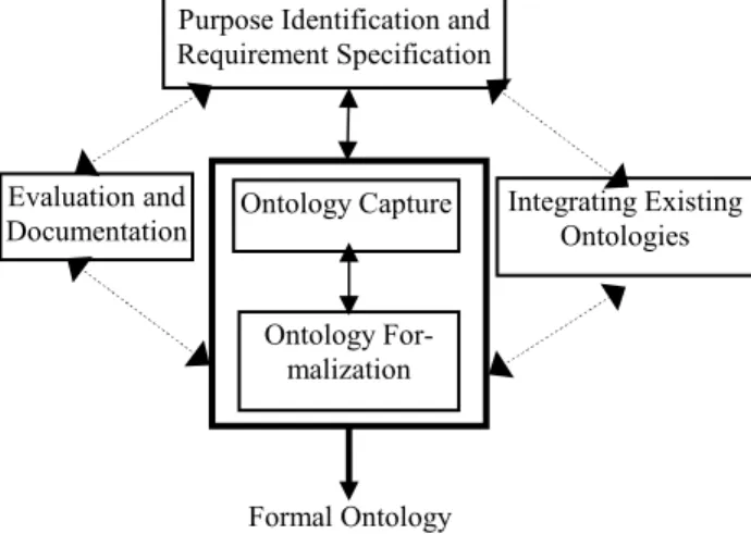
Figure 1 shows the steps in this ontology development process and their interrelationship. The dotted lines indi-cate that there is a constant interaction, albeit weaker, between the associated steps. The filled lines show the
main workflow in the ontology building process. The box involving the capture and formalization steps enhances the strong interaction, and consequently iteration, be-tween them.
Figure 1: Steps in the ontology development process.
ODEd aims to support this process. It allows compe-tency question definition, supports ontology capture by supporting the definition of concepts, relations and prop-erties using graphical representations, and it lets defining some classes of axioms, among others.
3.2 From Ontologies to Objects
Generally, a domain model is not directly useful to operational reuse. There exists a gap between the kinds and forms of the domain knowledge in a domain model and the content and form of software assets that can be reused in software construction. To bring this gap, we need to build a reuse infrastructure. This infrastructure should support the efficient operation of a reuse system and should also be adapted to its technology [16].
The ontology-based domain engineering approach proposes a set of directives, design patterns and transfor-mation rules for deriving object infrastructures from on-tologies. The directives are used to guide the mapping from the epistemological structures of the domain ontol-ogy (concepts, relations, properties and roles) to their counterparts in the object-oriented paradigm (classes, associations, attributes and roles, respectively). Design patterns and transformation rules are applied in axiom mapping.
Formal Ontology Purpose Identification and Requirement Specification
Ontology Capture
Ontology For-malization
Integrating Existing Ontologies Evaluation and
In the reuse infrastructure specification phase, the fol-lowing activities are proposed:
• Set-based ontology axiomatization: to derive
ob-jects from domain ontologies, it is worthwhile to adopt a formalism that lies at an intermediate ab-straction level between first-order logics and ob-jects. For this purpose, a hybrid approach based on pure first-order logic, relational theory and, pre-dominantly, set theory was proposed in [14]. So, the first step is to perform the complete axiomati-zation of the domain ontology using this set-based formalism.
• Class identification: starting from the sets formally
defined, a preliminary list of the classes of the ob-ject-oriented model can be established;
• Epistemological structure translation: since the
classes are defined, relations among concepts and epistemological axioms should be translated to the corresponding object-oriented structures, produc-ing an initial class diagram;
• Other axiom translation: the class diagram derived
in the step above should be refined to consider the others axioms that are not related to the structural organization of concepts and relations.
Finally, the reuse infrastructure should be imple-mented. The mapping directives and transformation rules proposed in [14] consider Java as the target programming language, so that the resulting reuse infrastructure is im-plemented as Java-objects.
ODEd partially supports this domain design and im-plementation process, leading to codifying ontologies in Java. In the next sections we present ODEd and how it partially supports this ontology-based domain engineering approach.
4
ODEd: ODE’s Ontology Editor
As pointed out in section 1, ODEd was developed to support domain engineering in ODE (Ontology-based software Development Environment), so that ODE could be considered a Domain Oriented Software Engineering Environment (DOSEE). To do this, ODEd’s requirements include [6]:
R1. Competency question definition: To support on-tology purpose identification and requirement
specification, ODEd should support competency questions definition.
R2.Concept, relation and property definition using a graphical language: During the ontology capture phase, the use of a graphical representation is es-sential in order to facilitate the communication between domain engineers and experts. Thus, ODEd should support the definition of concepts, relations and properties using a graphical lan-guage.
R3. Axiom definition: To support constraints captur-ing, ODEd should support axiom definition
.
R4. Ontology integration: A domain is, usually, wide and rich in details. A way to build large domain ontologies is to subdivide them in sub-ontologies. So, it is necessary to integrate them. Also, ontol-ogy integration is necessary to allow reuse of on-tologies previously defined.
R5. Ontology evaluation: it is important to guarantee that an ontology describes the domain it intends to model. Therefore, it is necessary to verify if the ontology is able to satisfy its requirements, i.e., its competency questions.
R6. Documentation of the ontology development proc-ess: like any software process, the ontology de-velopment process should be documented.
R7. Ontology instantiation: in DOSEEs, ontology in-stantiation is important because instances of main concepts can be defined and stored in do-main knowledge repositories, so that they can be used to support domain understanding.
R8. Domain investigation: in a DOSEE, during the software process, developers will use ontologies to learn about the domain. Therefore, ODEd should offer mechanisms to browse ontologies.
R9. Generating software assets from ontologies: To support domain design activities – reuse infra-structure specification and implementation, ODEd should support deriving reuse infrastructures from ontologies. If an ontology editor is capable of generating software assets from the ontology, these assets can be shared and reused by applica-tions developed in the DOSEE. In this way, knowledge reuse is promoted, once the assets are built based on the ontologies and several applica-tions can be developed using those assets.
according to a model defined in the domain layer. The
data management layer is responsible for the physical storage of the ontologies developed.
Figure 2: ODEd’s Architecture.
This architecture uses a three-tier design philosophy that suggests that the central classes, in the domain layer, are not aware of how the ontologies are presented to the user (presentation layer) or stored in the system (data management layer). The portion of the system that han-dles the graphical representation of the ontologies (pres-entation layer) is independent from the rest of the archi-tecture and it communicates with the domain layer. The data management layer provides the basic infrastructure for storing and retrieving objects in the system. Its pur-pose is to isolate the impacts of the technology of data management on the editor's architecture.
Since presentation and domain layers are very impor-tant for understanding ODEd’s working, following they are discussed in more details.
4.1 ODEd’s Presentation Layer
The presentation layer supports the ontology capture using graphical representations (R2). In ontology build-ing, a graphical representation is basically a language representing a meta-ontology. So, this language must have basic primitives to represent a domain conceptuali-zation and, in its simplest form, it should have notations to represent concepts, relations and properties [2].
Falbo et al. [2] proposed LINGO as a graphical lan-guage for capturing ontologies. LINGO has basic primi-tives to represent concepts, relations and properties. In addition to these basic notations, LINGO has other nota-tions to capture some types of relanota-tions (such as whole-part and subsumption, among others) that have a strong semantics and, indeed, hide a set of well-defined con-straints. This is a striking feature of LINGO and what makes it different from other graphical representations: any notation beyond the basic ones aims to incorporate a set of well-defined constraints [2]. This way, using these notations, axioms are automatically incorporated to the ontology. These axioms concern simply the structure of the concepts and are called epistemological axioms (EA).
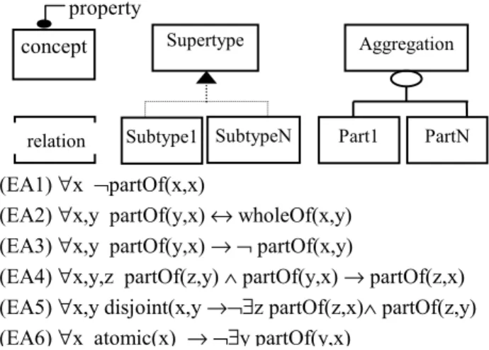
Figure 3 shows the main notations of LINGO and some of the epistemological axioms imposed by the whole-part relation. These axioms form the core of the mereological theory as presented in [17].
ODEd uses LINGO as a graphic language to describe
ontologies, allowing the automatic inclusion of LINGO’s notation built-in axioms. Using these notations during ontology capture, an ontology engineer is also defining the axioms that they represent.
Figure 3: LINGO’s main notations and some axioms.
ODEd allows ontology capturing in UML too. UML has also been used as an ontology modeling language [18]. However, it is necessary to emphasize that there are some problems in using UML as an ontology modeling language. First, an important criterion to evaluate ontol-ogy design quality is minimum ontological commitments [10]. Based on this principle, an ontology modeling lan-guage must embody only notations that are necessary to express ontologies. This is not the case of UML and ma-jority graphical languages available. Second, since on-tologies intend to be formal models, it is important that the language used to describe them has formal semantics. Again, this is not the case of the majority graphical lan-guages available, including UML [19]. However, we cannot ignore that UML is a standard and its use is widely diffused. Moreover, there are efforts to define UML se-mantics, such as pUML [20]. Based on that, ODEd uses a subset of UML’s elements that plays the same role of LINGO’s notation, i.e., these UML’s elements are applied using the same semantics imposed by the corresponding elements in LINGO. For instance, the epistemological axioms imposed by the whole-part relation presented in Figure 3 are also automatically incorporated to the ontol-ogy by ODEd when the aggregation notation of UML is used. In fact, ODEd has its internal meta-ontology model, described in the domain layer, that could be presented using LINGO or UML.
Figure 4 shows the subset of UML’s elements used in ODEd. Stereotyped classes (<<Concept>>) represent concepts. Relations are defined as labeled associations, and properties are represented as attributes. Relations that contain properties or relation of arity bigger than two are
Presentation Domain Data
Aggregation
Part1 PartN
Supertype
Subtype1 SubtypeN (EA1) ∀x ¬partOf(x,x) (EA2) ∀x,y partOf(y,x) ↔ wholeOf(x,y) (EA3) ∀x,y partOf(y,x) →¬ partOf(x,y)
(EA4) ∀x,y,z partOf(z,y) ∧ partOf(y,x) → partOf(z,x) (EA5) ∀x,y disjoint(x,y →¬∃z partOf(z,x)∧ partOf(z,y) (EA6) ∀x atomic(x) → ¬∃y partOf(y,x)
concept
Figure 4: Subset of UML to represent ontologies.
ODEd allows the ontology engineer to choose the graphical representation to be used. The ontology can be
captured in LINGO or UML, but this is only its graphical representation. The elements that capture the ontology in the domain layer are created independently of the graphi-cal representation used. I.e., in spite of different presenta-tion representapresenta-tions, the ontology domain model is the same. The presentation layer only provides an interface for capturing ontologies and improves modularity by encapsulating the way their contents are represented.
4.2 ODEd’s Domain Layer
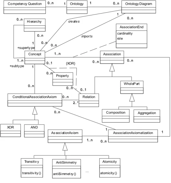
Figure 5 shows the domain layer’s model, that de-scribes how ontologies are internally represented in ODEd.
Composition
XOR AND
Aggregation Whol eP art
AssociationEnd
cardinality rol e Co mpeten cy Questi on
As soci ationAx iom Ontology 1 0..n 1 0..n Relation AssociationAxiomatization 1..n 0..n 1..n 0..n Ontology Diagram 0..n 1 0..n 1 Property 0..1 0.. n 0..1 0.. n ConditionalAssociationAxiom 2.. * 0..n 2.. * 0..n 1 0..n 1 0..n Association 0..n 1 0..n 1 Concept 0..n 1 0..n 1 0..n 0..n 0..n 0..n 0..1 0..n 0..1 0..n 1 0..n 1 0..n 0..n 1 ..n 0..n 1 ..n Hi erarchy 1 0..n +superty pe 1 0..n 1 ..n 0..n +subty pe 1 ..n 0..n Transitiv y
transitiv ity ()
AntiSimmetry
ant iSi mmet ry ()
Atomicity
atomicity () ...
cre ate s impor ts
{XOR}
Figure 5: ODEd’s Layer Domain Model. Concept1 <<Concept>> Concept2 <<Concept>> 1..* 0..* relation relation property <<Relation>>
The ontology purpose and its intended uses are identi-fied through competency questions. An ontology is repre-sented by a set of ontology diagrams, which contains
concepts created in or imported to the ontology. Con-cepts are related through associations and hierarchies. Hierarchies denote subsumption relationships. Associa-tions can be relations or whole-part relationships, which in turn are classified into aggregation and composition. Concepts and relations may have properties and in an
association, concepts have roles and cardinalities. Associations may have a set of constraints, expressed as association axioms, that defines the association axio-matization. Association axioms are classified into: reflex-ivity, irrreflexreflex-ivity, symmetry, anti-symmetry, atomicity, disjointed, exclusivity, and transitivity. This categoriza-tion is based on the axiom categories proposed by Staab and Maedche [21]. Each association axiom is dealt by a subclass of AssociationAxiom (some of these classes are presented in Figure 5). These classes are re-sponsible for checking if the constraints imposed by the corresponding axiom type holds. For instance, the
anti_symmetry() method of the AntiSymmetry
class is responsible for checking if a relation is anti-symmetric. It executes a method relation() (repre-senting a relation among concepts) of an object obj
(representing an instance of a concept). If obj is not returned by relation, then the anti-symmetry property is truth and the relation is anti-symmetric.
Sometimes, two or more relations have some condi-tional constraints related to a concept. This is the case of the associations involving Property in Figure 5. A property belongs either to a concept or to a relation. To deal with these situations, conditional association axioms
(XOR and AND) were defined.
As discussed in the previous subsection, LINGO’s no-tations have built-in axioms, called epistemological axi-oms (EA), and ODEd is able to automatically capture those axioms. For example, Whole-Part axiomatization includes the following association axioms: irrreflexivity, anti-symmetry and transitivity.
But besides the epistemological axioms, other axioms can be used to represent knowledge. These axioms can be of two types [2]: consolidation axioms (CA) and onto-logical axioms (OA). The former aims to impose con-straints that must be satisfied for a relation to be consis-tently established. The latter intends to represent declara-tive knowledge that is able to derive knowledge from the factual knowledge represented in the ontology.
To deal with these kinds of axioms, ODEd allows the ontology engineer to define his/hers own axiomatizations and to apply them to relations in the ontology, in an
ap-proach similar to that presented in [21]. The core idea is to use the axiom categorization to provide a compact, intuitively and accessible representation to certain wide-spread axiom types.
To support association axiomatization in ODEd, the Pre-Condition Pattern defined in [14] was applied. This pattern establishes that: ∀x:X, y:Y relation(x,y) → (pre-Condition1) ∧ (preCondition 2) ∧ ... ∧ (preConditionN).
In other words, it guarantees the evaluation of each one of the preconditions before a relation can be established. This pattern uses the Template Method pattern [22], where the template method is the method setRela-tion() and the hook methods are those responsible for evaluating the fulfillment of the preconditions.
In ODEd, the hook methods are the methods of the classes representing the association axioms. They are responsible for evaluating the fulfillment of the precondi-tions of the corresponding association axioms. Thus, the PreCondition Pattern applied in ODEd has the following format: ∀x:X, y:Y relation(x,y) → (associationAxiom1) ∧ (associationAxiom2) ∧ ... ∧ (associationAxiomN).
5
Developing an Ontology of Software
Quality Using ODEd
To show how ODEd supports ontology development, we use as an example the Software Quality Ontology
developed in [19]. Due to limitations of space, we present only part of this ontology.
Following the ontology development process scribed in section 3.1, the first step of the ontology de-velopment is the purpose identification and requirement specification. To support this activity (R1), ODEd allows the user to define competency questions, as shown in Figure 6. It should be pointed out that, in the current version of ODEd, competency questions are written in natural language (informal competency questions) and are used only for documentation purposes.
Once the competency questions are defined, ontology capture can begin. To support this activity, ODEd sup-ports a graphical representation of the ontologies using LINGO and UML (R2), as discussed in section 4.1. Fig-ure 7 shows part of the Software Quality Ontology [19], written in LINGO.
(represented by the roles super and sub characteristic), and its value is computed by the aggregation of their sub-characteristic measures. A measurable quality character-istic can be directly quantified applying some metric. The second classification enforces that product quality characteristics should only be used to evaluate software artifacts and process quality characteristics are used to evaluate software processes. Artifact is a concept im-ported from the Software Process Ontology [2], which were integrated with the software quality ontology been presented.
Figure 6: Competency questions of the Quality Ontology.
Finally, the valuation relation indicates that a
non-measurable quality characteristic can be valued through other measurable or non-measurable quality characteris-tics.
Cardinalities are used to show how many instances of a concept can participate in a relation. In Figure 7, cardi-nality (1,n) in the relation quantification implies that a measurable characteristic must be valued by, at least, one metric: (∀qc) (mensqc(qc) → (∃m) (quantifi-cation(qc,m)). Cardinality (1,1) still adds that a metric evaluates only one measurable characteristic: (∀m, qc1, qc2) (quantification(m,qc1) ∧ quantification(m,qc2) → qc1 = qc2). Since cardinality (0,n) does not impose any constraint, it is not represented.
Figure 8: Representing the Software Quality Ontology using UML.
Table 1 presents some axioms of the quality ontology, indicating their type: epistemological axioms (EA), onto-logical axioms (OA) or consolidation axioms (CA).
ID Axiom
EA 1
(∀ qc) (nmensqc(qc) → qchar(qc))
EA
2 (∀ qc) (mensqc(qc) → qchar(qc))
EA
3 (∀ qc) (prodqc(qc) → qchar(qc))
EA
4 (∀ qc) (procqc(qc) → qchar(qc))
EA 5
(∀ qc1, qc2) (subqc(qc1, qc2) → ¬ subqc(qc2 , qc1))
EA
6 (∀ qc) (mensqc (qc) ↔¬ (∃ qc1) (subqc(qc1, qc)))
EA 7
(∀ qc1, qc2, qc3) (subqc(qc1, qc2) ∧ subqc(qc2,
qc3) → subqc(qc1 , qc3 ))
EA 8
(∀ qc1, qc2) (disjointed(qc1, qc2 ) ↔ ¬ (∃ qc3 )
(subqc(qc3, qc1) ∧ subcarq(qc3, qc2 )))
OA 1
(∀ qc, qc1) (valuation(qc, qc1) →¬ valuation(qc1, qc))
Table 1: Some axioms of the Software Quality Ontology.
Axioms (EA1) to (EA4) refer to the super-type tion among quality characteristics. The whole-part rela-tion between quality characteristics imposes the con-straints defined by axioms (EA5) to (EA8). The ontology engineer does not need to write down these axioms, since ODEd automatically captures them from the graphical notation used.
The axiom (OA1) refers to the valuation relation. It indicates that, if a qualitycharacteristic qc1 is valuated by a qualitycharacteristic qc2, then qc2 cannot be valu-ated by qc1. In other words, it means that the valuation
relation is anti-symmetric. So, the anti-symmetry associa-tion axiom should be incorporated to its corresponding association axiomatization. Figure 9 shows how tion axioms can be manually incorporated to an associa-tion axiomatizaassocia-tion in ODEd. This form allows the on-tology engineer to associate axioms to a relation. In the example shown, anti-symmetry is the only axiom that composes the valuation’s axiomatization.
This is the way ODEd currently supports axiom defi-nition (R3). Thus, other axioms that do not fit in the axiom categorization defined cannot be captured. This issue is now being studied, and preliminary results are described in [23].
Figure 9: Defining Relation Axiomatization in ODEd.
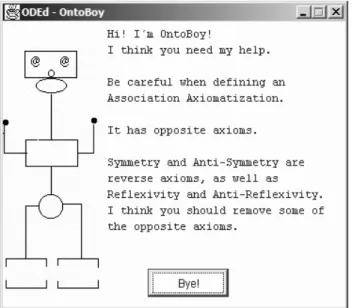
agents were added to ODEd to alert the user about even-tual structural modeling mistakes and to offer advices on how to solve them according to the user's actions. For example, if the ontology engineer also includes the sym-metry axiom in the valuation’s axiomatization (presented in Figure 9), the agent points that Symmetry and Anti-Symmetry are opposite axioms and offers a suggestion to solve the problem: remove one of them, as shown in Figure 10.
Figure 10: The OntoBoy agent.
The main purposes of the software quality ontology are: (i) to promote software quality knowledge integra-tion in ODE, a software engineering environment, and (ii) to support the development of quality management tools for it [19]. Therefore, this ontology must be inte-grated to the software process ontology [2] used to sup-port ODE’s software process definition and project track-ing.
ODEd supports ontology integration (R4) in a very limited way: concepts from existing ontologies can be imported to the current one. Also, if more than one con-cept is imported and there are relations between them, these relations are also imported to the ontology.
For example, in Figure 7, the Artifact concept was imported from the software process ontology and a rela-tion between Artifact and ProductQualityCharacteristic
was created (relevance).
If an imported concept or relation is removed from the original ontology, it is automatically removed from the ontology it was imported and no kind of notification is sent to the ontology engineer. It means that if Artifact
is removed form the software process ontology, it will be removed from the quality ontology, as well as the
rele-vance relation. In fact, in the current version, ODEd does not treat ontology evolution nor check consistency among imported concepts and existing concepts.
Finally, in its current version, ODEd does not support ontology documentation (R6). Also ODEd’s support to ontology evaluation (R5) is very weak, based on ontol-ogy instantiation (R7), as discussed in section 8.
6
From Domain Ontologies to Objects
As pointed in section 3.2, for deriving object infra-strucures from ontologies, Guizzardi et al. [14] defined a set of mapping directives, design patterns and transfor-mation rules. To deal with the requirement of generating software assets from ontologies (R9), in its current ver-sion, ODEd considers the mapping directives and some design patterns. But, since ODEd does not yet completely support axiom definition, except those described through association axiomatization, the transformation rules are not being treated. Following, we present how ODEd generates a Java infrastructure from the software quality ontology.
6.1 Mapping Directives
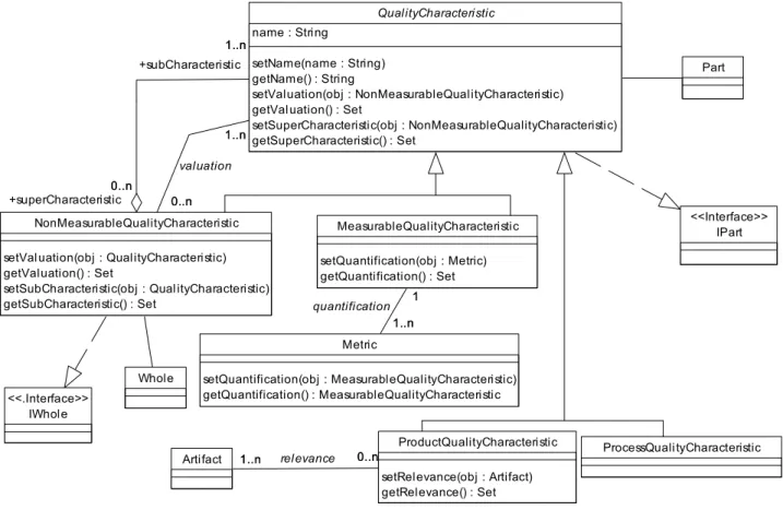
Figure 11 shows the object model derived from the software quality ontology. Classes, like Quali-tyCharacteristic and NonMeasurableChar-acteristic, were derived from the corresponding concepts. Also, associations, like quantification,
relevance, and valuation, were derived from the corresponding relations. Properties of the concepts were mapped as attributes of the corresponding classes, as it is the case of the property name of the concept Quali-tyCharacteristic, which was mapped as the attribute
name in the class QualityCharacteristic. For each derived attribute, methods to get and set values are created.
Still considering the mapping of relations, there are other issues that must be discussed. First, since in an ontology relations are bi-directional, the corresponding associations must be navigable in both directions. Thus, the associations are implemented as attributes, and there are methods in both classes to return them. The returned type of these methods depends directly on the cardinality associated to the relation [14]. For instance, since in the scope of the quantification relation a measurable charac-teristic may be evaluated by several metrics, the method
quantifica-tion()method is a MeasurableCharacteristic, since a metric is associated with just one characteristic.
Unary relations are also mapped as associations, and
methods are also generated for each association end. However, the name of these methods is, instead of the relation’s name, the name of the roles played by the cor-responding concepts.
Figure 11: Part of the Object Infrastructure for Software Quality generated by ODEd.
Subtype-of relationships among concepts can be directly mapped to inheritance among classes. So, axioms (EA1) to (EA4) do not require any special treatment. In our example, the subtype hierarchy of quality characteris-tic gives rise to the following sub-classes: Proc-essQualityCharacteristic, ProductQual-ityCharacteristic, NonMeasurableChar-acteristic and MeasurableCharacteristic. The class that represents the super-type ( Quali-tyCharacteristic) is mapped to an abstract class.
6.2 Mapping Axioms
When considering axiom mapping to the correspond-ing object infrastructure, we should discuss epistemologi-cal axioms separately from the others.
As pointed above, subsumption relationships can be directly mapped to class inheritance, and its axioms do
not require any special treatment.
This is not the case of whole-part relations. The un-derlying axioms implied by the proposed notation are not well mapped to aggregation in an object model, i.e., UML notation for aggregation does not guarantee the fulfillment of the imposed constraints of whole-part rela-tions. To deal with this problem, Guizzardi et al. [14] proposed the Whole-Part Pattern, shown in Figure 12. In this pattern, the Whole class is responsible for assuring to an associated concrete class (class A in Figure 12) the verification of the whole-part set of constraints before a whole-part relation is established. The interfaces
IWhole and IPart must be implemented by the corre-sponding concrete classes.
In the software quality domain infrastructure (Figure 11), the classes NonMeasurableCharacteristic
and QualityCharacteristic implement interfaces
IWhole and IPart, respectively. Likewise, they are
IPart <<Interface>> MeasurableQualityCharacteristic
setQuantification(obj : Metric) getQuantification() : Set
Metric
setQuantification(obj : MeasurableQualityCharacteristic) getQuantification() : MeasurableQualityCharacteristic
1
1..n 1
1..n
quantification
Whole
NonMeasurableQualityCharacteristic
setVal uation(obj : Qual ityCharacteristic) getValuation() : Set
setSubCharacteristic(obj : Qual ityCharacteristic) getSubCharacteristic() : Set
QualityCharacteristic
name : String
setName(name : String) getName() : String
setValuation(obj : NonMeasurableQualityCharacteri stic) getVal uation() : Set
setSuperCharacteristic(obj : NonMeasurableQualityCharacteristic) getSuperCharacteristic() : Set
0..n 1..n
0..n 1..n
valuation
0..n
1..n
+superCharacteristic 0..n
+subCharacteristic 1..n
Part
Artifact
ProductQualityCharacteristic
setRelevance(obj : Artifact) getRelevance() : Set
1..n 0..n
1..n rel evance 0..n ProcessQuali tyCharacteristic IWhole
related to the handlers Aggregation and Part, re-spectively. As shown in the code fragment below, sub-characteristics of a non-measurable characteristic is ac-cessed through Aggregation. The inclusion of a new
sub-characteristic is made by including a new part in the aggregation. Axioms (EA5) to (EA8) are checked when the method setPart() is evoked.
<<SetElement>>
whole() : Whole <<IWho le> >
part() : Part <<IPart>>
A ggregat ion
specConstrain() di sjoint ness() setDisjoint()
Composit ion
specConstrain(IPart p) : boolean exclusiviness(IPart p) : boolean
Whole
part : Set whole : IWhole
specConstrain(I Part p) : boolean ge tP art() : S et
setPart(IPart) rem ove Part (I Pa rt ) A
getB() : B setB(IPart p) removeB(IPart p)
Part
whole : Set
getWhole() setWhole() removeWhole()
B
getA() : A setA(IWho le w) removeA(IWhole w)
Figure 12: The Whole-Part pattern [14].
public class
NonMeasurableCharacteristic implements IWhole {
Aggregation a = new Aggregation();
public boolean setSubCharacteristic
(QualityCharacteristic c)
{
return a.setPart(c); }
public Set getSubCharacteristic () {
return a.part(); }
}
As discussed in section 4, to support association axiomatization in ODEd, the Pre-Condition Pattern [14] was applied. So this pattern is used jointly with the Whole-Part Pattern, and it required changes in the last one. Instead of implementing the axioms of the whole-part axiomatization, the Wholeclass is now related to the corresponding association axioms that compose the whole-part axiomatization, as shown in the code frag-ment below. In this way, the setPart() method in the
Whole class evokes the association axiom classes ( An-tiSymmetry, Atomicity, Transitivity, and
public abstract class Whole {
IWhole whole;
Set part = new Set();
AntiSymmetry s = new AntiSymmetry(); Atomicity a = new Atomicity();
Transitivity t = new Transitivity(); AntiReflexivity r = new
AntiReflexivity(); public boolean setPart(IPart c)
{
boolean result = false; if (specConstrain(c)) &&
transitivity(this,c,“getPart”)&& anti_symmetry(this,c,“getPart”)&& anti_reflexivity(this,c,“getPart”)&&
atomicity (this,c,“getPart”))
{
result = true; part.add(c);
(c.part()).setWhole(whole); }
return result; }
}
To deal with the axioms that are incorporated to asso-ciation axiomatizations (like is the case of the valuation
relation shown in Figure 9), a similar approach to the whole-part relation is used. Each class involved in a rela-tion is associated with the associarela-tion axiom classes that compose the relation axiomatization. When an instance of this relation is to be created, the axioms are checked. The code fragment below shows this approach applied to the valuation relation.
public abstract class
QualityCharacteristic implements IWhole { Set valuation = new Set();
AntiSymmetry s = new AntiSymmetry();
public Set getValuation() { return valuation; }
public boolean setValuation
(NonMeasurableCharacteristic c) {
boolean result = false; if s.anti_symmetry(this,
c,“valuation”) {
result = true; valuation.add(c); c.setValuation (this); }
return result; }
}
Since QualityCharacteristic partakes of the
valuation relation (that is anti-symmetric), it is re-lated to the AntiSymmetry class through the attribute
s. Before setting a non-measurable characteristic as ca-pable of valuating the current quality characteristic (this), the valuation axiomatization should be checked. To verify axiom (OA1), the method
s.anti_symmetry(this, c, “valuation”)
of the Anti-Symmetry class is executed. This method evokes the getValuation() method from the non-measurable characteristic c. If the current characteristic (this) is not in the valuation list of c, then it does not value c. Therefore, the axioms (OA1) holds and c can be added to the valuation list of the current quality char-acteristic.
7
Browsing Ontologies
To support domain investigation (R8), ODEd pro-vides automatic generation of hypertexts based on the ontologies designed. Using these hypertexts, developers can browse and search the domain concepts, relations, properties and constraints.
The language chosen to build these documents was XML [24], because it allows defining the syntax of struc-tured documents. Besides, XML schema and ontologies have a common goal: to provide vocabulary and structure for describing information to be exchanged (although XML does not provide semantics for a domain conceptu-alization, as ontologies do).
To generate the XML documents, a set of tags was defined to represent the ODEd’s ontology description model (concepts, properties, relations, and so on, as shown in Figure 5). Ontologies were mapped to XML files, marked with these tags. The code fragment below presents the definition of the QualityCharacteristic con-cept (<CONCEPT>) in a XML file. It is possible to see its description (<DESCRIPTION>) and its properties (<PROPERTY>). The tags <ISSUPERTYPEON/> and
<ISSUBTYPEON/> indicate, respectively, in which
hierarchies this concept is a super and a sub-type.
<CONCEPT oid="1859:8">
<NAME>QualityCharacteristic</NAME> <DESCRIPTION>attributes of an artifact or
of a software process used to evaluate the quality of a software product or process.
</DESCRIPTION>
</PROPERTY>
<ISSUPERTYPEONoid="1859:24"/> <ISSUBTYPEONoid="1859:25"/>
</CONCEPT>
All the elements that compose the document are iden-tified by the property oid (object identifier) in the tags. This identifier allows to associate elements inside the XML document. The code below, for example, presents the hierarchy (<HIERARCHY>) of the QualityCharacter-istic concept. The tags <SUPERTYPE/> and
<SUBTYPE/> indicate, through the identifier oid, which concepts are the super-type and the subtypes of the hier-archy, respectively. In the example, the super-type of the hierarchy is the concept which oid is equal to "1859:8"
(QualityCharacteristic).
<HIERARCHY oid="1859:24"> <SUPERTYPE oid="1859:8"/>
<SUBTYPE oid="1859:10"/> <SUBTYPE oid="1871:1"/> </ HIERARCHY >
It should be noted, however, that XML only deals with data and does not deal with visual presentation of documents. To define the presentation format of XML documents, style sheets are used. A style sheet allows to indicate to the browser how the user wants to present the content of the elements in the XML document. To pre-sent XML documents, ODEd uses XSL (eXtensible Style sheet Language) [25], a document transformation and formatting language. In the editor, it was defined a style sheet capable of presenting the documents that represent the ontologies in the hypertext format. Thereby, the hy-pertexts are presented to the user as HTML documents.
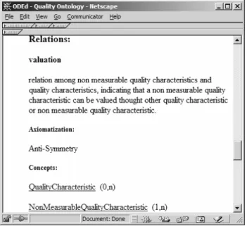
Figure 13 shows the hypertext derived from the soft-ware quality ontology. It is possible to visualize all on-tology’s concepts and relations and their definitions and properties. From the valuation relation, for example, the user can browse its concepts and visualize their defini-tions.
Figure 13: Browsing the Software Quality Ontology.
8
Ontology Instantiation in ODEd
As discussed in section 4, instances of domain con-cepts and relations can be used to support domain under-standing in a DOSEE (R7). Moreover, specially when relations are instantiated, it is possible to check if the constraints imposed by the corresponding axiomatization are the right ones. This is a way to partially evaluate an ontology (R5), though limited.
To support ontology instantiation in ODEd, a set of functionalities was developed, including functionalities to create databases to store the instances, and forms to in-stance data input. The object infrastructure derived from the ontology (discussed in section 6) is also used, since instances of concepts and relations are, in fact, instances of the corresponding classes and associations in the ob-ject infrastructure. So, the classes in the infrastructure must have access to the database created to insert, re-trieve, delete and update its instances. But those classes should not have direct access to the database, because this approach would decrease the object infrastructure reuse potential. Thus classes providing the basic services for storing and retrieving objects in the database are also generated. These classes are called shadow classes [26] and their purpose is to isolate the impacts of the technol-ogy of data management on the object infrastructure.
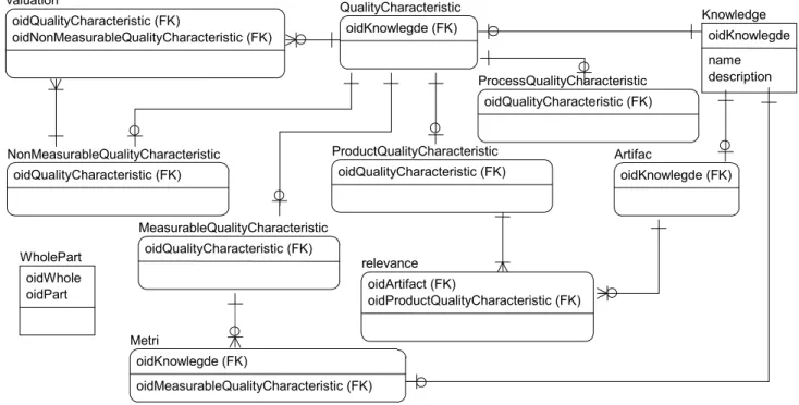
Figure 14 shows the database schema generated by ODEd to instantiate the Software Quality Ontology. For each class in the object infrastructure derived from the ontology (see Figure 11), a table is created. Since every concept is described by name and description prop-erties, a super-class Knowledge is created in the object infrastructure, and all classes derived from the ontology’s concepts inherit from it. In the database, there is a respec-tive Knowledge table that maps this class. Every table derived from a concept is related to the Knowledge
table to map this inheritance, except those that are de-rived from subclasses in the infrastructure, which are related to the tables that represent their super-types.
In the example shown in Figure 14, table
Quali-tyCharacteristic is related to table Knowledge,
NonMeasurableQualityCharacter-istic table, in turn, is related to table
QualityChar-acteristic, since
Figure 14: The database of the Quality Ontology.
When an instance of a concept, such as Metric, is created, a register is inserted in the corresponding con-cept’s table (Metric in the example). Also a register is automatically inserted in the table Knowledge to store the values of the properties name and description.
One-to-one (1:1) and one-to-many (1:N) binary rela-tions are mapped as foreign keys. In table Metric, for example, the foreign key oidMeasurableQuali-tyCharacteristic links a metric to the quality char-acteristic it quantifies.
Many-to-many (N:N) binary relations, relations with arity bigger than two, and relations with properties are mapped to associative tables, whose primary keys are the identifiers of the classes involved in the relation. In the relation valuation, for example, table valuation was created with the following composed primary key:
oid-QualityCharacteristic plus
oidNonMeasur-ableQualityCharacteristic.
To treat whole-part relations, a unique table
WholePart was created. In this table the oid for each instance that belongs to a whole-part relation is stored. The identifiers oidWhole and oidPart represent, respectively, the object whole and its part. For example, to include a quality characteristic c1 as a sub-characteristc of a non-measurable quality characteristic
c2, the register (oidC2, oidC1) is created in the table
WholePart.
As discussed early, the classes in the object infrastruc-ture must have access to the database generated. To do so, besides generating the database and the domain classes in the object infrastructure, a persistence layer is also automatically generated by ODEd.
For each concept or relation that has a domain class in the object infrastructure, a shadow class is created in the persistence layer. All the operations of the persistence mechanism are encapsulated in the shadow classes. Each one of those classes presents the necessary functionality to implement the persistence of the objects, such as to save, to remove or to update an object, and to retrieve a group of objects. For example, a class QualityChar-acteristicPers is created. It is responsible for ma-nipulating, in the database, the objects of the class
QualityCharacteristic.
Relations that generate associative tables and do not have their own shadow classes are handled by the shadow classes of the concepts involved in the relation. The relation valuation, for example, is manipulated by the classes QualityCharacteristicPers and
NonMeasurableQualityCharacteristicPers. Each one of these shadow classes has a method, as shown below, to insert a register in the associative table
valuation
oidQualityCharacteristic (FK)
oidNonMeasurableQualityCharacteristic (FK)
MeasurableQualityCharacteristic
oidQualityCharacteristic (FK) NonMeasurableQualityCharacteristic
oidQualityCharacteristic (FK)
ProcessQualityCharacteristic
oidQualityCharacteristic (FK)
WholePart
oidWhole oidPart
ProductQualityCharacteristic
oidQualityCharacteristic (FK)
Knowledge
oidKnowlegde
name description
relevance
oidArtifact (FK)
oidProductQualityCharacteristic (FK) QualityCharacteristic
oidKnowlegde (FK)
Artifac
oidKnowlegde (FK)
Metri
oidKnowlegde (FK)
valuation.
public void insertValuation(String obj, String obj1) {
String sLocSQL; Statement oLocSt; try {
sLocSQL = "INSERT INTO valuation (oidQualChar,oidNonMensQualChar) VALUES ('"+obj+"','"+obj1+"')"; ...
oLocSt.execute(sLocSQL); ...
}
catch (Exception e)
{ e.printStackTrace(); } }
Before inserting a register in the table valuation, it is necessary to check the theory of the relation valua-tion. Thus, the QualityCharacteristic class is associated to the QualityCharacteristicPers
class and the insertion method of the shadow class is called by the method setValuation, which is respon-sible for checking the valuation theory.
public abstract class
QualityCharacteristic implements IWhole
{
QualityCharacteristicPers pers = new
QualityCharacteristicPers(); Set valuation = new Set();
AntiSymmetry s = new AntiSymmetry();
public Set getValuation() { return valuation; }
public boolean setValuation
(NonMeasurableCharacteristic c) {
boolean result = false; if s.anti_symmetry(this,
c,“valuation”) {
result = true; valuation.add(c);
c.setValuation (this);
pers.insertValuation
(this.getOID,c.getOID); }
return result; }
}
Finally, to support instance data input, customized forms are generated, based on the ontology contents, in
an approach similar to that implemented in Protégé-2000 [27]. All forms for concept instantiation have text fields to input data concerning the properties name and descrip-tion. If a concept has other properties, more complex forms are generated, allowing data input for all proper-ties. One-to-one (1:1) and one-to-many (1:N) binary relations can also be instantiated when the concept is instantiated, in an approach analogous to that applied to properties.
Figure 15 shows the form for instantiating the Metric
concept. The instance created is named Test Re-startability. Since Metric does not have other properties than name and description, this form has only the corresponding two text fields. To allow data input for the quantification relation (a one-to-many (1:N) relationship), there is a list that enables the user to choose the measurable quality characteristic the metric quanti-fies. In the example, the Test Restartability metric quanti-fies the Testability quality characteristic.
Figure 15: Creating an instance of Metric.
For instantiating many-to-many (N:N) relationships, the user should choose an instance of one of the concepts involved in the relation. Then, he/she has to choose, among the instances of the other concept, those that are linked to the first.
Figure 16 presents the instantiation of the valuation
relation for the Maintainability instance. In the example,
Maintainability can be valuated by several quality char-acteristics, such as Analysability and Testability. A list of all quality characteristics already instantiated is exhibited and the user should select those that valuate Maintain-ability.
Maintainabil-ity as a quality characteristic that valuates Testability, because the relation valuation is anti-symmetrical.
Figure 16: Instantiation of the relation valuation.
9
Related Work
There are many ontology editors presented in the lit-erature, such as Ontolingua Server, OntoEdit, OILEd, JOE, Protége-2000 and WebODE.
Ontolingua Server [28] supports ontology develop-ment and sharing. It provides access to a library of on-tologies, and allows new ontologies to be created. Re-motely distributed groups can use their web browsers to browse, build and maintain ontologies stored in the server.
OntoEdit [21] pursues an approach such that graphi-cal means exploited for modeling of concepts and rela-tions scale up to axiom specificarela-tions (using RDFS). The core idea is to use an axiom categorization. This catego-rization is centered around axiom semantic meaning rather than syntactic representation.
OILEd [29] supports the construction of ontologies in OIL. The editor allows defining concepts and relations and also supports the definition of some pre-defined axioms. OILEd has reasoning services that supports on-tologies construction, integration and verification.
The Java Ontology Editor (JOE) [30] was developed to help users build and browse ontologies. It enables query formulation at several levels of abstraction. JOE
provides a graphical user interface for editing ontologies. It uses Entity Relationship diagrams to represent them.
Protége-2000 [27] aims to support knowledge acqui-sition, and to reach interoperability with other knowledge representation systems. It has classes, instances of these classes, slots representing attributes of classes and in-stances, and facets expressing additional information about slots. Protégé-2000 generates knowledge-acquisition forms automatically based on the types of the slots and restrictions on their values, allowing ontology instantiation.
Ontobroker [31] provides languages to annotate web documents with ontological information, to represent ontologies, and to formulate queries. The tool set of On-tobroker enables users to access information and knowl-edge from the web and to infer new knowlknowl-edge with an inference engine.
browser, inference engine and axiom generator. The graphical user interface allows browsing all the relation-ships defined on the ontology as well as graphical-pruning these views with respect to selected types of relationships. Mathematical properties such as reflexive, symmetric, etc. and other user-defined properties can be also attached to the "ad hoc" relationships.
All editors previously mentioned were developed to support ontology design in the context of Semantic Web. None of them was developed aiming to support a domain engineering process. ODEd’s main purpose is to fill this lacuna. Thus one striking feature of ODEd is to support ontology-to-objects mapping.
Despite of being an important requirement for ontol-ogy design, few ontolontol-ogy editors address adequately the
existence of graphical facilities for ontology capturing. Most of them allow creating concept taxonomies and some of them relations. Generally, no semantics is asso-ciated with the meta-ontology that underlies the graphical language used. JOE and WebODE, for example, use some graphical language to represent ontologies. But the first one uses Entity Relationship models, and the second one does not define any special notation for the kinds of relations supported by the editor. ODEd adopts LINGO, a graphic language specially designed for ontology’s repre-sentation. However, ODEd does not ignore the impor-tance of other graphical languages available. Therefore it also supports ontology capture using UML, but using LINGO’s semantics.
Concerning constraints definition, a very interesting initiative is the creation of axioms templates in OntoEdit [21]. This approach was considered in ODEd in order to facilitate axioms definition. But it is still necessary to define how to represent other types of axioms as pro-vided in WebODE [32].
Reasoning services are an important feature [30, 33] because they can be used in ontology evaluation. Other desirable services provided by some of these tools are the support to the cooperative work and the automatic gen-eration of ontology documentation in HTML [28, 30, 33]. This last feature is addressed by ODEd but no rea-soning service is available.
Finally, in ontology instantiation, ODEd uses a simi-lar approach to Protégé-2000 [27].
10 Conclusions and Future Work
In this paper, we presented ODEd, an ontology editor
that supports ontology development using graphical rep-resentations, besides promoting automatic inclusion of some classes of axioms and derivation of object infra-structures from ontologies. ODEd was built to support an ontology based approach for domain engineering in ODE, a software engineering environment.
Table 2 summarizes how ODEd’s requirements (pre-sented in section 4) were addressed in the current version.
Requirements ODEd Comment
R1 Competency question definition
Limited Only informal competency questions
R2 Ontology capture using graphical notation
Yes Using LINGO and UML
R3 Axiom definition Partial Only certain axiom types
R4 Ontology integration Limited Manual, with no check
R5 Ontology evaluation Limited Through ontology instantiation
R6 Documentation of the ontology development process
No -
R7 Ontology instantiation Yes Java code generation
R8 Domain investigation Yes XML and hypertexts in HTML
R9 Generating software as-sets from ontologies
Yes Object infra-structure in Java
Table 2: Requirement support in ODEd..
Although most phases of ontology development proc-ess are supported by ODEd, there are many aspects to be improved.
First, ODEd should also support defining formal competency questions. This feature is related to ontology evaluation. Once competency questions could be for-mally captured, they can be used to evaluate if the ontol-ogy satisfies its requirements. To support these features, reasoning services are necessary.
now working to improve this aspect [23]. In the new approach, axioms can be defined in KIF [34], and checked using the JTP (Java Theorem Prover) [35] infer-ence engine. Since JTP reads DAML + OIL [36] sen-tences, the ontologies are translated to this standard. This way, ontology exchanging will be considered.
There are other aspects to be improved in ODEd. On-tology integration, for instance, is limited, since ODEd does not deal with inconsistencies among imported con-cepts and existing concon-cepts. Although ODEd supports ontology capture using graphical notations, this process is manual. ODEd does not offer any facility to support automatic capture of ontology concepts and relations.
In spite of its limitations, ODEd is an important step ahead towards domain orientation in software engineer-ing environments. It supports an ontology-based domain engineering process and can be used to support knowl-edge reuse in a DOSEE.
11
Acknowledgments
The authors acknowledge CAPES and CNPq for the financial support to this work.
References
[1] B. Chandrasekaran, J. R. Josephson, V.R. Ben-jamins. What are Ontologies, and Why Do We Need Them? IEEE Intelligent Systems, p. 20-25, January/February 1999.
[2] R.A. Falbo, C.S. Menezes, A.R.C. Rocha. A Systematic Approach for Building Ontologies. In Proceedings of the 6th Ibero-American Confer-ence on Artificial IntelligConfer-ence, Lisbon, Portugal, Lecture Notes in Computer Science, vol. 1484, 1998.
[3] O. Lassila, F. Van Harmelen, I. Horrocksm, J. Hendler, D.L. Mcguinness. The Semantic Web and its Languages. IEEE Intelligent Systems, p. 67-73, November/December 2000.
[4] R.A. Falbo, A.C.C. Natali, P.G. Mian, G. Ber-tollo, F.B. Ruy. ODE: Ontology-based software Development Environment. In Proceedings of the IX Argentine Congress on Computer Science, CACIC’2003, p. 1124 – 1135, La Plata, Argen-tina, 2003.
[5] K.M. Oliveira, A.R.C. Rocha, G.H. Travassos, C.S. Menezes. Using Domain Knowledge in
Software Engineering Environments. In Pro-ceedings of the 11th International Conference on Software Engineering and Knowledge Engineer-ing, SEKE'99, Kaiserslautern, Germany, 1999.
[6] P.G. Mian, R.A. Falbo. Building Ontologies in a Domain Oriented Software Development Envi-ronment. In Proceedings of the IX Argentine Congress on Computer Science, CACIC’2003, p. 930 – 941, La Plata, Argentina, 2003.
[7] R.A. Falbo, G. Guizzardi, K.C. Duarte. An On-tological Approach to Domain Engineering. In
Proceedings of the 14th International Confer-ence on Software Engineering and Knowledge Engineering, SEKE'2002, p. 351- 358, Ischia, Italy, 2002.
[8] M. Uschold, M. Gruninger. Ontologies: princi-ples, methods and applications. In Knowledge Engineering Review, vol. 11, no. 2, June 1996.
[9] N. Guarino. Understanding, building and using ontologies. Int. Journal Human-Computer Stud-ies, 46(2/3), February / March 1997.
[10] T.R. Gruber. Toward principles for the design of ontologies used for knowledge sharing. Int. Journal Human-Computer Studies, 43(5/6), p. 907-928, 1995.
[11] M. Gruninger, J. Lee, Ontology Applications and Design, Communications of the ACM, Vol. 45, No. 2, p. 39-41, February 2002.
[12] N. Guarino. Formal Ontology and Information Systems. In N. Guarino (Ed.), Formal Ontolo-gies in Information Systems, IOS Press, 1998.
[13] R. Jasper, M. Uschold. A Framework for Under-standing and Classifying Ontology Applications. In Proc. of the 12th Workshop on Knowledge Acquisition, Modeling and Management (KAW’99), Alberta, Canada, 1999.
[14] G. Guizzardi, R.A. Falbo, J.G. Pereira Filho. Using Objects and Patterns to Implement Do-main Ontologies. Jornal of the Brazilian Com-puter Society, vol. 8, no. 1, July 2002.
[15] M. Grüninger, M.S., Fox. Methodology for the Design and Evaluation of Ontologies. Technical Report, University of Toronto, 1995.
[17] W.N. Borst. Construction of Engineering On-tologies for Knowledge Sharing and Reuse. PhD Thesis, University of Twente, Enschede, The Netherlands, 1997.
[18] S. Cranefield, M. Purvis. UML as an Ontology Modelling Language, In Proceedings of the IJCAI-99, Workshop on Intelligent Information, 16th International Joint Conference on AI, Stockholm, Sweden, July 1999.
[19] R.A. Falbo, G. Guizzardi, K.C. Duarte, A.C.C. Natali. Developing Software for and with Reuse: An Ontological Approach, Proceedings of the International Conference on Computer Science, Software Engineering, Information Technology, e-Business, and Applications - CSITeA'2002, p. 311 - 316, Foz do Iguazu, Brazil, June 2002.
[20] A. Evans, S. Kent. Core Meta-Modelling Se-mantics of UML: the pUML Approach, In 2nd International Conference on the Unified Model-ing Language, Colorado, EUA, 1999.
[21] S. Staab, A. Maedche. Ontology Engineering beyond the Modeling of Concepts and Relations. In 14th European Conference on Artificial Intel-ligence, Workshop on Applications of Ontologies and Problem-Solving Methods, 2000.
[22] E. Gamma, R. Helm, R. Johnson, J. Vlissides.
Design patterns: elements of reusable object-oriented software, Addison-Wesley, 1995.
[23] V.E.S. Souza, R.A.Falbo. Building Axioms and Evaluating Ontologies in ODEd. In Proceedings of the XVII Brazilian Symposium on Software Engineering – X Tool Session, p.7-12, Manaus, Brazil, October 2003 (in portuguese).
[24] T. Bray, J. Paoli, C.M. Sperberg-McQueen. Extensible Markup Language (XML) 1.0. W3C Recommendation, 1998.
[25] A. Rabarijoana, R. Dieng, O. Corby. Exploita-tion of XML for Corporate Knowledge Man-agement. In Proceedings of 11th European Workshop on Knowledge Acquisition, Modeling
and Management, EKAW’99, p. 373-378,
Dagstuhl Castle, Germany, 1999.
[26] E. Yourdon; Object-Oriented Systems Design: an Integrated Approach, Yourdon Press Com-puting Series, Prentice Hall, 1994.
[27] N.F. Noy, M. Sintek, S. Decker, M. Crubézy, R.W. Fergerson, M.A. Musen. Creating Seman-tic Web Contents with Protégé-2000, IEEE
Intel-ligent Systems, March/April 2001.
[28] A. Farquhar, R. Fikes, J. Rice. The Ontolingua Server: a tool for collaborative ontology Con-struction. Int. J. Human-Computer Studies, 46, p. 707-727, Knowledge Systems Laboratory, Stanford University. Stanford, CA, USA, 1997.
[29] S. Bechhofer, I. Horrocks, C. Goble, R. Stevens. OilEd: a Reason-able Ontology Editor for the Semantic Web. In Working Notes of the 14th International Workshop on Description Logics (DL-2001), p.1-9, Stanford, EUA, August 2001.
[30] K. Mahalingam, M.N. Huhns. A Tool for Orga-nizing Web Information. IEEE Computer, p. 80-83, June 1997.
[31] D. Fensel, S. Decker, M. Erdmann, R. Studer. Ontobroker: Or How to Enable Intelligent Ac-cess to the WWW. In Proceedings of the 11th Banff Knowledge Acquisition for Knowledge-Based System Workshop, Banff, Canada, April 1998.
[32] J.C. Arpírez, O. Corcho, M. Fernández-López, A. Gómez-Pérez. WebODE: a Scalable Work-bench for Ontological Engineering. Proceedings of the First International Conference on Knowl-edge Capture, K-CAP’01, Victoria, Canada, 2001.
[33] M. Fernandez, A. Gomez-Perez, N. Juristo, METHONTOLOGY: From Ontological Art Towards Ontological Engineering. In Proceed-ings of the Workshop on Ontological Engineer-ing. Spring Symposium Series. AAAI’97, Cali-fornia, USA, 1997.
[34] M.E. Genesereth, R. Fikes. Knowledge Inter-change Format, Version 3.0 Reference Manual. Technical Report Logic-921, Computer Science Department, Stanford University, 1992.
[35] F. Gleb, A General Interface for Interaction of Special-Purpose Reasoners within a Modular Reasoning System, In Question Answering Sys-tems. AAAI Fall Symposium, p. 57-62, 1999.
[36] D. Connolly, F. van Harmelen, I. Horrocks, D.L. McGuinness, P.F. Patel-Schneider, L.A. Stein,


![Figure 12: The Whole-Part pattern [14].](https://thumb-eu.123doks.com/thumbv2/123dok_br/18976461.455493/14.918.132.771.209.744/figure-the-whole-part-pattern.webp)