PAPER • OPEN ACCESS
Feedback strategy for closed-loop inspection based on STEP-NC
To cite this article: Cristhian I. Riaño and Alberto J. Álvares 2018 J. Phys.: Conf. Ser. 1065 082014
View the article online for updates and enhancements.
Feedback strategy for closed-loop inspection based on
STEP-NC
Cristhian I. Ria˜no1, Alberto J. ´Alvares1
1Department of Mechanical Engineering, Bras´ılia University - Campus Universit´ario Darcy
Ribeiro, Bras´ılia - CEP 70910-900, Brazil
E-mail: [email protected], [email protected]
Abstract. The dimensional inspection is currently consolidated as an important tool in the improvement of manufacturing processes. The demands of quality and the requirement of parts with complex specifications propose new challenges, such as the incorporation of integration and interoperability concepts in measurement operations. An important issue still unresolved in the inspection process is the dynamic management of information that requires solutions that are at the technological forefront and contextualized within the requirements of Industry 4.0. In this perspective, the implementation of a closed-loop inspection supports the measurement requirements for different manufacturing processes and enables the application for different purposes. The feedback strategy proposed in this article proposes an alternative as a solution to integrate the inspection results of a part within a digital manufacturing chain based on STEP-NC (STandard for the Exchange of Product model data - Numerical Control). The mechanisms for acquisition, processing, and analysis of information, and the control architecture that complement the feedback strategy is exposed.
1. Introduction
The concept of smart manufacturing, integrated and interoperability is strongly related to the industry 4.0 approach [1]. Different cutting-edge technologies converge in this line to use the information to optimize processes and maximize efficiency. Constant advances in measurement have allowed technological developments in both equipment and data processing and analysis techniques, but there are still barriers that prevent fully integrating digital technologies into the inspection process. One of these barriers is the exchange of information between systems involved in the manufacture of a part [2].
The importance of the information obtained in an inspection process is that the data can be used in other functions besides the already conventional quality control of a part. The data acquired in the measurement provide both uncertainty and deviation values, as well as relevant information on the manufacturing process and manufacturing conditions[3, 4]. Previously, the measurement process was limited to taking measurements within a controlled environment to calculate error values, but the demands of efficient processes made measurement an indispensable tool to control and monitor in manufacturing the evolution of a product[5, 6].
To exchange information, it is necessary to use a neutral data model, with open architecture and homogenized syntax. This need to transfer information between manufacturing systems led to the emergence and evolution of standards such as IGES (Initial Graphics Exchange Specification), PDES (Product Data Exchange Specification), STEP (Standard for the Exchange
2
of Product Model Data), among others. The problem of integrating GD&T specifications,
execute the measurement, exchanging inspection data, analyzing results and making decisions is still far from automatic and much of the problem lies in the data structures used to transfer the information.
Within this context, a strategy for feedback of inspection results in a close-loop inspection based on AP242, AP238 and AP219 protocols of ISO 10303 is presented in this article. The model allows a bidirectional flow of information between the processes involved in the process life cycle of a part.
2. CAD data requirements for inspection
To perform the inspection it is necessary to obtain information from the model product in addition to the project requirements. In the proposed application scenario the part design is developed based on features. Feature-based part modeling technology is the primary component in integrating the processes associated with the product life cycle of a part. The STEP standard mainly uses this technology to provide a neutral, interoperable format for the exchange of product information. In building the product model based on the STEP standard it is necessary to use the unit of functionality (UoF) provided by the application protocols to define the features and their properties.
There are different tools to aid in the process of creating CAD models, but it is vitally important to develop a measurement plan. The measurement plans contain all the necessary information to control the CMM (Coordinate-measuring machine), in the execution and evaluation of the measurement. The inspection plan creates a procedure to define both the
execution program and a method of post-processing of data. The plan produces a set of
measurement points and a list of features along a path to be inspected. The task of greater relevance in the plan is the extraction of information that is hampered by the absence of a standard that harmonizes the definitions included in the DMIS, I ++ DME, AP219, ISO 14649, Part 16, DML, QMD among other standards used in the measurement.
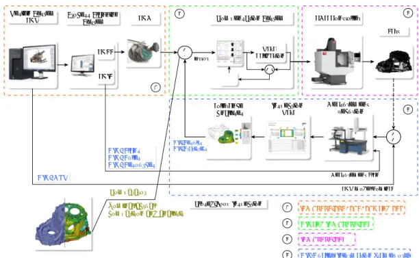
The Figure 1 shows the feedback scheme based on the STEP standard. The manufacturing and measurement requirements are extracted from a STEP AP242 PMI file to generate a STEP AP238 file with manufacturing operations. Measurements are made by comparing the mathematical definition of the model with the definition that can be computed by measuring points on the model.
3. Closed-loop inspection
The measurement system acquires data of the geometry of the piece manufactured in several points located in different dimensional planes, with these values the control system reconstructs the surface, analyzes and processes the results to quantify the error, identify the causes and generate the compensation. The expert system in charge of processing a large part of the information bases its operations on structured knowledge within a set of rules aimed at maximizing the efficiency of the process. The compensation in the process is generated directly in the program sent to the control system of the machine tool, which contains the execution routines to machine a new part. Inspection is repeated after machining, this reduces the error in each closed-loop system interaction.
The control strategy within the closed-loop inspection seeks to compensate the input data to the control system of the CNC with the results of a comparison between the design nominal and the inspected part to meet the quality requirements of the project. The Figure 2 presents the control scheme for the integration model.
The close-loop control scheme shown in the Figure 2 contains as input the nominal information of the part where the requirements for quality control are defined. The compensation system is in charge of generating the orders sent to the CNC controller of the machine tool, adjusting
ROUND_HOLE WORKPIECE THROUGH_STEP SLOT_PARTIAL_ROUND CLOSED_SLOT THROUGH_SLOT MCS_MILL Machining workingsteps SENSORS PROGRAM_HEADER PART_ALIGNMENT MCS_TO_PCS FEATURES OUTPUTS CMM_PROGRAM Inspection workingsteps PROGRAM_HEADER_STATEMENT SPM600M_A0_B0 INSPECTION_PATHS CONSTRUCTED_FEATURES TOLERANCES Setup section Header section Inspection Result Data analysis system
Closed Slot Chamfer face
Through slot Circular Through Hole
Cylindrical Face Through step Leng th Width Height
Figure 1. Tolerance model for dimensional and geometric inspection.
the code of the nominal part with the necessary changes to satisfy the requirements. The CNC control system of the machine tool executes the numerical commands for machining the part. The inspection system, in charge of acquiring data of the manufactured part, plans, executes and analyzes the measurement results. On the inspection system is included the feedback strategy to exchange the data within an adherent data model with the ISO 10303.
In the manufacturing of part, different disturbances are present, for which errors of different nature (static, dynamic and progressive) are adhered to the process. The proposed inspection strategy aims to identify, monitor and control the errors that a part acquires during the manufacturing process in order to satisfy the expected GD&T requirements. The identification of sources of error uses so many inspection results as data of the manufacturing conditions obtained by monitoring the process. The compensation of the geometric error is based on the determination of the uncertainty of global form, product of a comparison of the nominal model with the real model and make the corrections on the data structure sent to the CNC controller of the machine tool.
4. Compensation strategy
The error compensation strategy uses the STEP standard data model to integrate the manufacturing and inspection processes. The application protocol AP219 of the ISO 10303 standard defines the context, scope and information requirements necessary to analyze and report dimensional inspection results, creating a mechanism for bidirectional exchange of information with other data models used in the product life cycle such as AP242, AP224 and AP238 application protocols.
The UoF functional limitations included in the AP219 has the harmonized entities that allow to define both the value of the deviation acceptable for the manufacture of the piece and the dimensional tolerances. The tolerances are applied to the elements defined within the entity shape aspect. Geometric tolerance is the maximum or minimum variation given for a position
4
Design System
CAD Process Planning System
CAPP CAIP + -Compensation System CAM + + Part CNC Controller Closed-Loop Inspection E Data Validation + -1 2 3 4 QIF - Plans QIF - Rules QIF - Resources QIF - MBD Inspection Data Measurement Plan CAD model nominal QIF-Results QIF-Statistics Measurement Execution Tolerance Analyses error
QIF and ISO 10303-238
QIF(Quality Information Framework)
ISO 10303-203, 214, 219 and 242
ISO 10303-238
Nominal/actual comparison and analysis
1 2 3 4 Comparator Nominal/actual comparison and analysis
Figure 2. Feedback strategy within the closed-loop inspection.
or geometric shape in the manufacturing process. The entity Geometric tolerance is used to define and exchange the data of the critical requirements of a piece by means of the concept of tolerance feature represented within the STEP standard as an attribute of shape aspect to specify a type of geometric feature.
5. Conclusions
The dimensional and geometric inspection allows implementing strategies to perfect the
manufacturing processes using correctly the obtained information. The feedback strategy
proposed in the article avoids the loss of information produced by format changes between systems because it uses a neutral data structure with homogenized syntax and semantics for different processes of the one-piece manufacturing life cycle. Automated operations, optimization techniques, and expert systems for decision-making can be easily implemented.
References
[1] X. Xu, Integrating advanced computer-aided design, manufacturing, and numerical control: principles and implementations. Information Science Reference-Imprint of: IGI Publishing, 2009.
[2] J. Lee, B. Bagheri, and H.-A. Kao, “A cyber-physical systems architecture for industry 4.0-based manufacturing systems,” Manufacturing Letters, vol. 3, pp. 18–23, 2015.
[3] P. Hu, Z. Han, H. Fu, and D. Han, “Architecture and implementation of closed-loop machining system based on open step-nc controller,” The International Journal of Advanced Manufacturing Technology, vol. 83, no. 5-8, pp. 1361–1375, 2016.
[4] F. Zhao, X. Xu, and S. Xie, “Step-nc enabled on-line inspection in support of closed-loop machining,” Robotics and Computer-Integrated Manufacturing, vol. 24, no. 2, pp. 200–216, 2008.
[5] R.-x. Xia, R.-s. Lu, Y.-q. Shi, Q. Li, J.-t. Dong, and N. Liu, “Caip system for visibased on-machine measurement,” in Seventh International Symposium on Precision Engineering Measurements and Instrumentation, vol. 8321. International Society for Optics and Photonics, 2011, p. 83213V.
[6] P. Wilma and M. Giovanni, “A frame for a computer aided inspection planning system,” International Journal of Engineering & Technology, vol. 4, no. 1, p. 125, 2015.