© 2005 Science Publications
Corresponding Author: M.R. Juhari, School of Mechatronic Engineering, Kolej Universiti Kejuruteraan Utara Malaysia (KUKUM), Jalan Kangar-Arau, 02600, Jejawi, Perlis, Malaysia, Tel: +60-4-9798335, Fax: +60-4-9798142
An Application of Finite Element Modelling to Pneumatic Artificial Muscle
1,2
R. Ramasamy,
2M.R. Juhari,
3M.R. Mamat,
2S. Yaacob,
2N.F. Mohd Nasir and
4,5M. Sugisaka
1
DAG Technology (Malaysia) Sdn. Bhd., Lot 2-7 Innovation House, Technology Park Malaysia
Lebuhraya Puchong-Sg.Besi, 57000 Kuala Lumpur, Malaysia
2
School of Mechatronics Engineering, Kolej Universiti Kejuruteraan Utara Malaysia (KUKUM)
Jalan Kangar-Arau 02600 Jejawi, Perlis, Malaysia
3
Terengganu Advanced Technical Institute (TATI), Jalan Panchor, Teluk Kalong
24000 Kemaman, Terengganu, Malaysia
4
Advanced Research Institute for Science and Engineering, Waseda University
3-4-1 Okubo, Shinjuku, Tokyo, 169-8555 Japan
5
Department of Electrical and Electronics Engineering, Faculty of Engineering
Oita University, 700 Dannoharu, Oita-shi, 870-1192 Japan
Abstract: The purpose of this article was to introduce and to give an overview of the Pneumatic Artificial Muscles (PAMs) as a whole and to discuss its numerical modelling, using the Finite Element (FE) Method. Thus, more information to understand on its behaviour in generating force for actuation was obtained. The construction of PAMs was mainly consists of flexible, inflatable membranes which having orthotropic material behaviour. The main properties influencing the PAMs will be explained in terms of their load-carrying capacity and low weight in assembly. Discussion on their designs and capacity to function as locomotion device in robotics applications will be laid out, followed by FE modelling to represent PAMs overall structural behaviour under any potential operational conditions.
Key words: Artificial muscle, braided pneumatic muscle, fluid actuators, finite element analysis (FEA)
INTRODUCTION
Recently, pneumatic actuators have found their way into factory floor automation and have been widely used in robotics equipments. These actuators are usually cylindrical in shape and have since their advancement over the years; they become more attractive as a source of locomotion device in robotics. One of the desirable properties for pneumatic actuators is the relatively low weight in assembly, as compared to their electric and hydraulics counterparts. This enables an easy control over the end-effectors attached to these actuators, whereby delicate and fragile objects can be handled accordingly by controlling the air pressure, hence generating a ‘soft-touch’. Various types of pneumatic actuators used currently in the field are cylinders, bellows, pneumatic engines and pneumatic stepper motors. A lesser-known type in this category is the Pneumatic Artificial Muscles (PAMs). PAMs operate opposite to bellows, i.e., they contract when pressurized, generating a load-carrying capacity during this contraction. They are extremely lightweight due to simple core construction materials consisting of inflatable and flexible membranes, more desirable to be assembled into mobile robotics equipments.
Throughout literature, various names have been used to identify a PAM, which are, Pneumatic Muscle Actuators[1], Fluid Actuator[2], Fluid-Driven Tension Actuator[3], Axially Contractible Actuator[4] and Tension Actuator[5]. PAM operates by means of overpressure, whereby gas pressure is charged into the membranes to move loads, instead of discharging gas pressure out of the membranes, as in the case of underpressure operated bellows. Usually, an overpressure is easier to achieve than under pressure using gas compressors, noting that ambient pressure in the vicinity of 101.3 kPa.
Characteristics of PAMs: As described before, PAMs
Vmin
P = 0 Lmax
M
M M
L1
V1
P1
V2
P2 L2
(a) (b) (c)
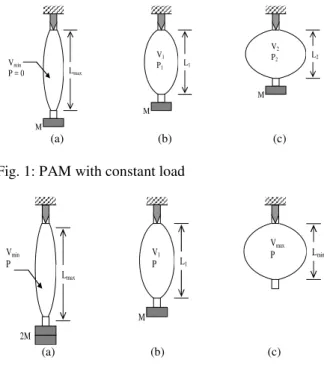
Fig. 1: PAM with constant load
Vmin
P
Lmax
2M
M L1
V1
P
Lmin
Vmax
P
(a) (b) (c)
Fig. 2: PAM with constant pressure
Fig. 3: Geometry model of braided PAM
This differentiates PAMs from other pneumatic devices like the bellows, which extends in length when pressurized. PAMs’ source of energy comes from pressurized gas, usually air, which is forced into the membranes. This pressurization creates a gauge pressure or differential pressure, which simply means the difference between the air pressure inside the membrane and that of the ambient atmospheric pressure outside the membrane. Therefore, a PAM is in fact powered by gauge pressure or differential pressure to carry loads. To understand the characteristics of PAMs, two simple experiments can be reviewed[6-8].
In Fig. 1, consider a mass M hanging at one end on a PAM which is fixed on the other end. The gauge pressure is increased from an initial value of zero. At zero gauge pressure shown in Fig. 1a, the enclosed volume is Vmin and the length is maximum which is
Lmax. As the gauge pressure in the muscle is increased
to a value P1 in Fig. 1b, the enclosed volume is now V1,
bulging radially, as the overall lengths begin contracting, generating a pulling force on the mass M, lifting it upwards until force equilibrium achieved, i.e., when the generated pulling force reaches the value of Mg (g = gravitational constant, 9.81 m/s2). A further increase in pressure to P2 in Fig.1c, increases the
enclosed volume to V2, lifting the mass M further
upwards by newly generated pulling force. This test revealed two obvious characteristics of PAMs: Firstly, PAM shortens in length by increasing its enclosed volume and secondly, it will contract against a constant load as pneumatic pressure is gradually increased.
A second experimental setup[6-8] will be reviewed for other characteristics of PAM as shown in Fig. 2. This time the gauge pressure is kept at a constant value, while the mass will be reduced from an initial value of 2M, as seen in Fig. 2a. As mass is reduced to value of M in Fig. 2b, the PAM shortens, while increasing its enclosed volume. As all mass is completely removed as depicted in Fig. 2c, the bulging goes to its full extent, PAM shortens to a minimal length Lmin and the pulling
force will drop to zero. At this point, there are no more contractions is possible on the PAM. Further deductions can be added to the existing PAM characteristics: Firstly, PAM contracts in length under constant pressure as loading is reduced and secondly, it reaches an optimal point at which no more contraction is possible and the pulling force has subsequently fallen to zero, under maximum enclosed volume. Based on both the experiments carried out and the four characteristics observed, a fifth characteristic can be derived: For each configuration of applied pressure and attached pulled load, there exists an equilibrium length on the PAM, exhibiting a spring-like behaviour.
Design of PAMs: PAMs were introduced in the 1930’s
by a Russian inventor named Garasiev[6]. This original design, however, is just a simple fluid-driven muscle-like actuator and due to limited material technology at the time, it was limited in use. Since then, several other designs have emerged with improved materials technology, leading to a more practical applicability of PAMs in the industry, particularly robotics. The braided muscle[9], composed of gas-tight elastic bladder, surrounded by braided sleeves as shown in Fig. 3, seems like a practical construction, consisting of a flexible membrane, enclosed by braid fibres running helically (at angles of +θ and -θ) about the muscle’s longitudinal axis.
by balancing internal pressure with tension in fibres. The fibres are locked at the PAM ends to balance external loads. The membranes will impose a pressing contact against the fibres, causing the fibres to curve outwards, shortening the overall PAM in the process, hence generating pulling force at the ends. This concept was originally introduced by McKibben[10] as an orthotic actuator in the late 1950’s due to its similarity in contractile skeletal muscles. Typical materials used for the membranes constructions are latex and silicone rubber, while nylon is normally used in the fibres. Looking at Fig. 3 and denoting Ls as length of each
fibre strand with n numbers of turns over the entire PAM, the enclosed volume of the membrane with fibre pitch angle θ, can be found to be:
3 2 s
2 L
V sin cos
4 n
= θ θ
π (1)
Thus, maximum enclosed volume may be achieved with a braiding angle of 54.7o. The force-carrying capacity of the PAM can also be deduced from the work-energy theorem[9]. Consider work done in expanding a PAM by dV by charging it with pressure P, amounting in net work of PdV, this work is then used to move a payload with generated force F over distance of dL, resulting work done by external force of FdL. Neglecting hysterisis and any loss of energy due to friction, the following terms can be expressed for the generated force, F:
F = -P dV / dL (2)
Based on equations (1) and (2), one can ideally predict the performance of a PAM in terms of force generated, contraction lengths and enclosed volume changes, without considering the losses due to friction, material hysterisis and membrane deformation given by:
2 2
2 Pb (3cos 1) F
4 n
θ − =
π (3)
It will be difficult to see the interweave angle θ during operation of PAM, therefore deriving (3) in terms of length L is desired and is given by the fact that:
L cos
b
θ = (4)
Thus:
2 2
2 2
Pb 3L
F 1
4 n b
= −
π (5)
It shows here that PAM tends to exhibit nonlinear spring behaviour with a varying stiffness. Stiffness, k, is simply the derivative of force with respect to length:
k = dF / dL (6)
and thus ignoring the pressure change over operational boundaries of the PAM, gives:
2 3PL k
2 n
=
π (7)
or in terms of length L:
2 6F k
b 3L
L
=
−
(8)
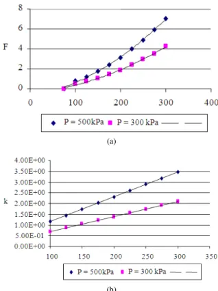
It can be seen from (3) to (7) that the force is a nonlinear function of length and that the stiffness is a linear function of length. Figure 4 shows a plot of theoretical pressure, force (a) and stiffness (b) as functions of length.
Finite element modelling: The FE modelling of PAM,
as in the preliminary stage, was undertaken to verify to some extent the capacities which can be predicted theoretically, namely the force generated via volume expansion and inflation pressure released into the membranes. The educational FEA code LUSAS was used in this exercise with presently the linear-static solver. The PAM was modelled as a cylinder with orthotropic material properties representing the layers of membrane and braids accordingly. This is shown in the Fig. 5.
(a)
(b)
Fig. 5: Orthotropic material layers
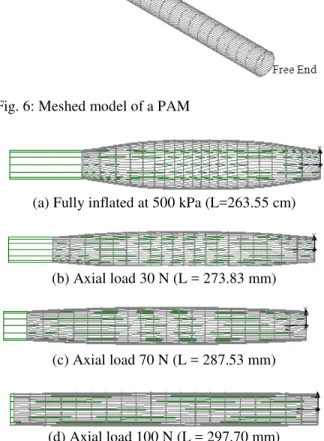
Fig. 6: Meshed model of a PAM
(a) Fully inflated at 500 kPa (L=263.55 cm)
(b) Axial load 30 N (L = 273.83 mm)
(c) Axial load 70 N (L = 287.53 mm)
(d) Axial load 100 N (L = 297.70 mm)
Fig. 7: Linear-static FEA results
Both the ends of the cylinder are restrained from any translational and rotational degrees-of-freedom, except the translational freedom to move along its longitudinal axis on one end, to represent the side which will be acting as actuating free-end. Loadings are applied in stages, beginning from the pressurization to inflate the entire structure applied in increments, followed by the force to pull the PAM at the free-end.
Fig. 8: FE results for force and length
Fig. 9: FE results for stiffness and length
The exercise is to observe the stiffness of an inflated PAM with constant air mass and fixed pressure by applying payload weights (forces) and recording the displacement produced by the length achieved. The FE shell mesh was applied onto the structure to account for loads and displacements in every direction along the Cartesian axis system. The completed model is shown in Fig. 6.
The loadings were applied in various load case stages, namely beginning with the pressurization to inflate the membrane from 0 to 500 kPa in increments of 100 kPa and then followed by axial force at the free end from 10 N to 100 N. A linear-static solution sequence was executed in this preliminary study first to understand the structural behaviour or the inflated PAM subjected to axial forces. The results obtained are shown in Fig. 7a-d. Plots showing the force-length relationship from the FE analysis are shown in Fig. 8.
Due to the simplified nature of this preliminary model, the F-L plots show a linearized curve, as compared to the parabolic plots obtained from the theoretical static model for PAM. Several changes required in the FE model, among the few, are a nonlinear material model to incorporate the hyperelastic membrane stretching-expansion and the oversimplified end-effects. The stiffness-length curve can also be plotted and is shown in Fig. 9.
CONCLUSION
scale in field applications. Their low assembly weight and high power-to-weight ratio is most desirable for PAMs to be considered for use in mobile robotics[11]. A future direction in this research will consider a more in-depth analysis into materials of construction for PAMs and testing in terms of actual functional performance as well as a localized strength envelope characteristic under operational conditions[12]. A possible functional setup to be setup may be in terms of a suitable mechanism as in previous study[11] and shall be a development to look forward to. A more detailed and realistic material model shall also be employed in the forthcoming FE models to represent PAMs more accurately. A more detailed geometry construction will also be necessary to represent the membrane-fibre interaction and fibres interweave interaction during pressurization.
REFERENCES
1. Caldwell, D.G., G.A. Medrano-Cerda and M.J. Goodwin, 1993. Braided pneumatic actuator control of multi-jointed manipulator. Proc. IEEE Intl. Conf. Syst., Man & Cyber., pp: 423-428, Le Touquet.
2. Yarlott, J.M., 1972. Fluid actuator. US Patent No.3 645 173.
3. Paynter, H.M., 1989. Hyperboloid of revolution fluid-driven tension actuators and methods of making. US Patent No. 4 733 603.
4. Daerden, F. and D. Lefeber, 2002. Pneumatic artificial muscles: actuators for robotics and automation. Eur. J. Mech. and Env. Eng., 47: 10-21.
5. Daerden, F. and D. Lefeber, 2001.The concept and design of pleated pneumatic artificial muscles. Intl. J. Flu. Pow., 2: 41-50.
6. Verrelst, B., F. Daerden, D. Lefeber, R. Van Ham and D. Verrelst, 2001.Pleated pneumatic artificial muscles: Compliant robotic actuators. 2001 IEEE/RSJ Intl. Conf. on Int. Rob. and Sys., 1958– 1963, Maui, Hawaii.
7. Verrelst, B., F. Daerden, D. Lefeber and R. Van Ham, 2001. Pleated pneumatic artificial muscles: Actuators for automation and robotics. 2001 IEEE/ASME Intl. Conf. Adv. Int. Mech., pp: 738-743, Como.
8. Klute, G.K. and B. Hannaford, 2000. Accounting for elastic energy storage in mckibben artificial muscle actuators. ASME J. Dyn. Sys., Meas. and Cont., 122: 386-388.
9. Chou, C.P. and B. Hannaford, 1996. Measurement and modelling of mckibben pneumatic artificial muscles. IEEE Trans. Rob. and Auto., 12: 90-102. 10. Klute, G.K and B. Hannaford. Fatigue
characteristics of mckibben artificial muscle actuators. Dept. of Electrical Engineering, University of Washington.
11. Verrelst, B., J. Vermeulen, B. Vanderborght and R. Van Ham. Motion generation and control for the pneumatic biped LUCY. Available Source Listed at URL www.clawar.com .