Application of Optical Multi-Stability to
Deflection Sensors
Shadi Hazzem Shehadeh, Michael Cada, Yuan Ma and Montasir Qasymeh
Abstract—In this work, the optical multi-stability is utilized in a deflection sensor element. We have found that a simple sensor, which consists of two cascaded Fabry-Perot resonators, has a novel memory property, besides having the ability to obtain instant deflection measurements. The essential operation of this device is conducted by an optically nonlinear refractive index change in the second resonator. As the second resonator is designed to be multi-stable, the first resonator has a movable mirror connected to a diaphragm, to sense a deflection change. We note that this proposed device has promising potential for the design of future smart sensors, which are further optically reconfigurable.
Index Terms— Fabry-Perot resonators, Intelligent sensors, Nonlinear optics, Optical bistability.
I. INTRODUCTION
The force of interaction between a manipulator and its environment can be measured by a number of technologies. As an external force is applied to a sensing element, a deformation or change in its shape is induced. This deformation can be detected either by using a measurement of the change of a physical property, such as resistance or capacitance, or directly through the use of an optical device. There are several types of micro force sensors, including strain gauge, piezoelectric, optical, and capacitive sensors. The optical sensors are recognized for their inherent advantages over other types of sensors.
Manuscript received July 26, 2009.
Shadi Hazzem Shehadeh is a Master’s Candidate with the Department of Electrical and Computer Engineering, Dalhousie University, Halifax, Nova Scotia, NS, B3J 1Z1, Canada, fax: 902- 422-7535; (e-mail: [email protected]).
Michael Cada is with the Department of Electrical and Computer Engineering, Dalhousie University; (e-mail: [email protected]).
Yuan Ma is with the Department of Electrical and Computer Engineering, Dalhousie University; (e-mail: [email protected]). Montasir Qasymeh is a PhD Candidate with the Department of Electrical and Computer Engineering, Dalhousie University; (e-mail: [email protected]).
For example, optical sensors grant immunity to electromagnetic interference, which in turn improves the operability in a harsh environment, as well as their capability to accept more than one input. Moreover, high miniaturization, flexibility and light weight are useful features offered when an optical route is used.
Optical sensors are usually composed of a diaphragm that can be deformed, and displaced by a certain distance from an optical fiber end. This displacement results in the formation of a resonant cavity [1]. The cavity length will change when a deflection of the diaphragm is applied. Once the change in the reflected or transmitted optical signal of known wavelength is detected, the induced deflection can easily be measured [2, 3].
In this work, a new modified structure is proposed. We suggest the sensor structure to consist of two cascaded optical resonators, instead of a single resonant cavity. The role of the second resonator is to operate as an all-optical multi-stable element, while the first resonator transforms the deflection change into light change. Consequently, we found that such a
deflection sensor is capable of recognizing
proceeding deflection values, thanks to the optical multi-stability. Furthermore, the sensor sensitivity, which is the ratio of the change in the output light intensity to the change in the induced deflection, is enhanced, thanks to an intensity jump from one stable output value to another.
The paper is organized as follows. In Section II the proposed structure is described and modeled. Section III presents the numerical simulations. Finally, section IV summarizes the results and conclusions.
II. OPTICAL STRUCTURE AND MODELING
As depicted in Fig. 1, the first resonator has a movable mirror that converts the applied deflection into a change on the second resonator’s input light.
Proceedings of the World Congress on Engineering and Computer Science 2009 Vol I WCECS 2009, October 20-22, 2009, San Francisco, USA
The second resonator is filled with a nonlinear material. A convenient nonlinear material that posses a strong nonlinear refractive index and weak absorption is required. After conducting a material’s survey, we found that castor oil is a good candidate [4]. A numerical example of the evolution of the proposed structure, utilizing the castor oil, will be provided.
Fig. 1. Optical structure.
The entire structure can be optically modeled by the light transmission. The overall light transmission can be given by [1]
Io= TT. Iin, (1)
TT = 1−RT, (2)
RT =
R1+RNL−2. R1.RNL.cos ϕ1
1+R1.RNL−2. R1.RNL.cos ϕ1 , (3)
whereϕ1=
4.π.L1.n1
λ , L1is the air-gap length, n1is
the linear refractive index of resonator 1, λ is the wavelength of the light source, R1is the reflectivity of
mirror 1. The nonlinear reflectivity of the second resonator RNL can be given by [5, 6]
RNL =
1+R02.e −2.α.L2−2.R0.e −α.L 2.cos (ϕ2)− 1−2.R0+R02.e −α.L 2
1+R02.e −2.α.L2−2.R0.e −α.L2.cos (ϕ2) ,
(4)
where R0=R2=R3, R2is the reflectivity of mirror 2,
R3 is the reflectivity of mirror 3, ϕ2= 4.π.L2
λ . n +
2. I0
TR 0. n2 , L2is the nonlinear material length, n is
the linear refractive index of resonator 2 , n2 is the
nonlinear refractive index of resonator 2, and
TR0 = 1−R0,α=α0+ 2I0
TR 0β, α0 is the linear
absorption coefficient and β is the nonlinear absorption coefficient. Here, all the mirrors are assumed lossless.
III. NUMERICAL SIMULATIONS AND RESULTS
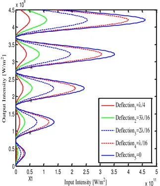
As the second resonator is designed to be optically multi-stable, a given input value has multiple possible output values. In addition, the first resonator is designed to transform the applied deflection change into a change in the second resonator light input. Therefore, in the case of having a fixed light input to the first resonator, a given deflection has multiple transmitted output light values. The relationship between the input and output intensities at different deflections is shown in Fig. 2.
Fig. 2. The the input and output intensities at different deflections.
As can be concluded from Fig. 2, the output space cannot directly be calculated from presumed inputs. This is because there are no unique solutions, as the case in most nonlinear systems. For example, for a given input light value, let’s say X1 in Fig. 2, there are many possible output values. We approached this numerical dilemma by calculating the output-input pairs in an inverse direction. We presumed
0 0.5 1 1.5 2 2.5 3 3.5 4 4.5 5
x 1011 0
0.5 1 1.5 2 2.5 3 3.5 4 4.5x 10
8
Input Intensity [W/m2]
O
ut
pu
t
I
nt
e
ns
it
y
[
W
/m
2]
X1 x
x x
Deflection 1=/4
Deflection 2=3/16
Deflection 3=2/16
Deflection 4=/16 Deflection
5=0 Proceedings of the World Congress on Engineering and Computer Science 2009 Vol I
WCECS 2009, October 20-22, 2009, San Francisco, USA
reasonable outputs and then solved the corresponding input values.
However, in the case of any multi-stable system, some of the possible input-output pairs might not be stable. Thus, a stable criterion is needed to identify the stable input-output pairs. It can be shown that each stable input-output pair obey the following condition [7]
ϕ2NL. dTNL
dϕ2 <
TNL
Io , (5)
whereϕ2NL =
4.π.L2
λ . 2.
n2
TR 0 and TNL = 1−RNL.
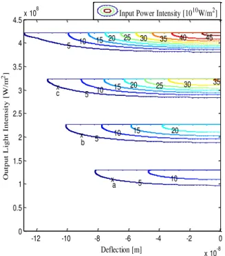
Hereby, a phase diagram of all possible stable optical outputs for a given input, as a function of the induced deflection can be obtained. In Fig. 3, such a phase diagram is shown, utilizing the castor oil in the second resonator.
Fig. 3. The phase diagram of all possible stable optical outputs. R1=0.35, R2=0.96, R3=0.96, L1=10.15µm,
L2=40µm and λ=514 nm.
Observing Fig. 3, one can see that the system evolution shows a hysteresis-like behavior, on the transmitted output light versus the applied deflection. In other words, at a certain induced deflection, the value of the transmitted optical output depends on the history of that applied deflection, as well as on its absolute value. For example, referring to Fig. 3 if the
input intensity is set to be 5×10¹°(w/m²) and the optical output threshold value taken as 0.977 × 10⁸
(w/m²) then as a deflection is applied, the output intensity will be correspondingly increased. If the applied deflection is released, after the output light reached point (a), the output light will consequently go back to 0.977 × 10⁸ (w/m²). However, if a further deflection is applied, the output will jump to point (b). Consequently, if the applied deflection is released, the output will be at another second threshold value of 1.83 × 10⁸ (w/m²). On the other hand, after reaching point (b), if a further deflection is applied, the output will be driven to point (c), where a third threshold value of 2.85 × 10⁸ (w/m²) is
obtained at zero applied deflection, and so on and so forth. Thus, it is evident that the system offers to memorize previous applied deflections.
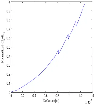
Moreover, the sensor sensitivity is expected to be enhanced, thanks to abrupt optical output jumps due the presence of unstable output ranges. The system sensitivity can be defined as the ratio of the change in the output to the change in the induced deflection. The sensitivity can be derived as
Isen =
−8.π
λ. 1+R1.RNL−R1−RNL . R1.RNL.sin ϕ1
ζ2 Iin –
d R NL
d Io R1−1.ζ+ −R1+ R 1 R NL 1 2
.cos ϕ1 . 1+R1.RNL−R1−RNL
,
(6)
where ζ= 1 + R1. RNL−2. R1. RNL. cos(ϕ1) and dRNL
dIo =
16.π.R0.L2.n2.sin ϕ2 .e −2.α.L 2.(1+Ro2−2.R0)
λ.TR 0.(1+R02.e −2.α.L 2−2.R0.e −α.L 2.cos (ϕ2))2 .
Fig. 4 shows the sensor sensitivity of the structure while utilizing the castor oil in the second resonator.
As can be seen in Fig. 4, the sensitivity is enhanced for the wider range of the applied deflection. This is another novel property of the structure in addition to the memory-like property. Deflection [m]
O
ut
pu
t
L
igh
t
Int
e
ns
it
y
[W
/m
2]
5 5
5 5
10 10
10
10 15
15 15
20 20
20 25
25 30
30
35
35 40 45
x x x
a b c
-12 -10 -8 -6 -4 -2 0
x 10-8 0
0.5 1 1.5 2 2.5 3 3.5 4 4.5
x 108 Input Power Intensity [1010W/m2]
Proceedings of the World Congress on Engineering and Computer Science 2009 Vol I WCECS 2009, October 20-22, 2009, San Francisco, USA
Fig. 4. The system sensitivity.
IV. CONCLUSIONS
A new deflection sensor structure, with two cascaded resonators, is proposed. The suggested structure has a novel property of having the optical output value, at a certain applied deflection, controlled by the history of that deflection. The first resonator is filled with air and has a movable mirror that is coupled to a diaphragm. The second resonator is filled with a nonlinear optical material. Furthermore, we found that the system sensitivity is enhanced due to the output jumps from one stable value to another. We count on these properties to increase the controlling and the sensing functionality and flexibility of novel devices and systems.
REFERENCES
[1] X. Wang, B. Li, O. L. Russo, H. T. Roman, K. K. Chin and K. R. Farmer , “Diaphragm design guidelines and an optical pressure sensorbased on MEMS technique,” Microelectronics J., vol. 37, no. 1, Jan. 2006, pp. 50–56. [2] M. Li, M. Wang, “Optical MEMS pressure sensor based on
Fabry- Perot interferometry,” in Optics Express, vol. 14, no. 4, , Feb. 2006, pp. 1497-1504.
[3] Y. Kim and D. P. Neikirk, “Micromachined Fabry-Perot cavity pressuretransducer,” IEEE Photonics Technol. Lett., vol. 7, no. 12, Dec.1995, pp. 1471-1473.
[4] R. F. Souza, M. A. Alencar, M. R. Meneghetti and J. M. Hickmann,“Nonlinear optical properties of castor oil,” Advanced Materials and Structures), XXIX ENFMC, Annals of Optics, 2006.
[5] G. R. Fowles, Introduction to Modern Optics, 2nd ed. New York: Dover, 1989, ch. 4.
[6] R. W. Boyd, Nonlinear Optics, 2nd ed. Amsterdam, The Netherlands: Academic. 2003, ch. 7.
[7] M. Qasymeh, M. Cada and S. Ponomarenko, “Quadratic Electro-Optic Kerr Effect: Applications to Photonic Devices,” IEEE J. Quantum Electron., vol.44, no.8, Aug. 2008, pp. 740-747.
0 0.2 0.4 0.6 0.8 1 1.2 1.4
x 10-7 0
0.1 0.2 0.3 0.4 0.5 0.6 0.7 0.8 0.9 1
Deflection[m]
N
or
m
a
li
z
e
d
dI
o
/dL
1
Proceedings of the World Congress on Engineering and Computer Science 2009 Vol I WCECS 2009, October 20-22, 2009, San Francisco, USA