Abstract— In this paper an improved version of zeroth order resonator (ZOR) using Left Handed Metamaterial (LHM) is reported, and its performance is compared with the earlier published ZOR. The resonator is designed based on microstrip technology using composite right left handed transmission line (CRLH TL) approach. The conventional ZOR is designed based on the CRLH TL along with two coupling slots at the input and output ports, whereas the proposed design of ZOR is based on coupling capacitors. Use of coupling capacitor in place of coupling slot improves resonance characteristic of ZOR in terms of return loss and insertion loss and also increases the operational bandwidth. The measured resonant frequency, return loss, insertion loss and fraction bandwidth of the proposed 1.5- unit cell ZOR are 1.5 GHz, -26.31 dB, -0.42 dB and 20.66% respectively, whereas for the conventional 1.5-unit cell ZOR these measured parameters are 1.8 GHz, -6.63 dB, -9.09 dB and 0.77% respectively. The frequency parameter and performance of the resonators are evaluated by full-wave electromagnetic simulator, IE3D, based on method of moments (MoM) and all these results are verified by measurements.
Index Terms— Composite right left handed transmission line, Interdigital capacitor, Left handed metamaterial, Zeroth order resonator.
I. INTRODUCTION
The unique properties of left handed metamaterials (LHMs) have brought novel concepts in electromagnetic propagation characteristics, and novel devices [1]-[8]. Two methods are reported for realization of LHMs-(a) resonant approach [2], using SRR with metal wire (b) transmission line approach [3] using inert digital capacitor (IDC) and stubs, also known as non resonant approach. The resonant approach towards LH metamaterials is not practical in microwave applications due to following reasons; bulky in size, narrow-band and lossy due to the requirement of operation near SRR resonance. The transmission line approach using left-handed transmission line (LH-TL) made up of IDC and shorted stub inductor was reported in [3], [4], [5]. The CRLH TLs based design of dominant mode leaky-wave antenna uses the properties of anti-parallel phase and group velocity [4]. The LHMs can have the positive, negative and even zero value of the propagation constant over a frequency range. At zero propagation constant the LHMs based resonator has an infinite wavelength and hence its resonance frequency becomes independent of the size of the resonator. Therefore, the zero propagation constant property of resonators enables them to be more compact than conventional
An Improved Zeroth Order Resonator
using Left Handed Metamaterial
Dileep Kumar Upadhyay, Srikanta Pal
Department of ECE, Birla Institute of Technology, Mesra, Ranchi-835 215, Jharkhand, India E-mail:[email protected]
right handed (RH) half-wavelength resonator [3], [5]. Although these LHMs based resonator are smaller in size as compared to the conventional RH resonator, though it has limited application in wireless communication system because of their narrow bandwidth. The ZOR reported in [3] has the fractional bandwidth of 0.77% whereas the fractional bandwidth reported in [5] for ZOR antenna is
~0.2%.
This paper presents an improved zeroth order resonator based on CRLH TL with two coupling capacitors at input and output ports. The CRLH TL uses combination of inter digital capacitor (IDC) in series and via to the ground plane at the stub ends in shunt. A conventional ZOR of the same class based on the CRLH TL with two coupling slots at the input and output ports is also presented for the performance comparison. The proposed ZOR is having the extended bandwidth of 20.66% as compared to 0.77% for the conventional ZOR, and also improved performance in terms of return loss and insertion loss.
II. THEORY OF CRLH TL AND ZOR
The equivalent circuit model of CRLH TL unit-cell is shown in Fig. 1, which consists a series RH inductance (LR), a series LH capacitance (CL), a shunt RH capacitance (CR), and a shunt LH
inductance (LL). If Zs and Yp are respectively the per unit length series impedance and per-unit length
shunt admittance of CRLH TL unit cell shown in Fig.1, then these can be expressed as [7], [8], [9]
( )
= − 1 (1)L R S C L j Z
ω
ω
ω
( )
= − 1 (2)L R P L C j Y
ω
ω
ω
The shunt frequency (ωsh = ω1) and the series frequency (ωse = ω2) are given by
) 3 ( 1 L R se C L = ω ) 4 ( 1 R L sh C L = ω
The propogation constant(βCRLH)
, and sign function
(s(ω)),
for the CRLH unit-cell are given by[3], [4], [6], [7].
) 5 ( 1 ) ( 2
2 + − +
Fig. 1. Equivalent circuit model of CRLH TL unit-cell.
Fig. 2. Dispersion curve of CRLH TL unit-cell.
If ωse and ωsh are unequal as shown in the dispersion diagram of Fig. 2, such type of CRLH TL is known as unbalanced CRLHTL. At these resonant frequencies (ωse and ωsh), where β = 0, an infinite wavelength can be supported. According to the theory of the open-ended resonator with the CRLH TL [3], [7], [8], its resonance occurs when
) 7 ( ))
1 ( ., ,... 2 , 1 , 0
( = ± ± ± −
= n N
l n
n π β
Where, l, n and N are the physical length of the resonator, mode number, and number of unit cells, respectively. When n is zero, the wavelength, λg =2π |βn|
,
becomes infinite and the resonantfrequency of the zeroth-order mode becomes independent of the size of the resonator, while the shortest length of the conventional open ended resonator is one half of the wavelength. Thus, a resonator with a more compact size can be realized.
As shown in Fig.2 for the unbalanced CRLH TL, two resonant frequencies, (ωsh = ω1) and (ωse =
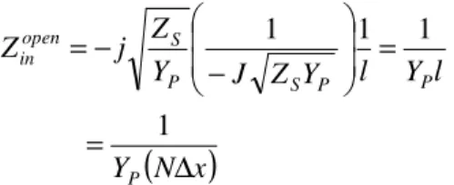
ω2), with β = 0 are observed with a matched load. Considering the open-ended TL, where load impedance Zl = ∞, the input impedance (Zin) seen from one end of the resonator toward the other end is given by [7], [8]
) 8 ( 1
) cot(
0
l jZ l
jZ
Z C C
open in
β β β≈ − −
=
(
)
(9) 11 1 1
x N Y
l Y l Y Z J Y Z j Z
P
P P
S P
S open
in
∆ =
= −
− =
Where ZC and ∆xare the characteristics impedance and unit-cell length of the CRLH TL.
From (9) it can be observed that the input impedance of the open-ended resonator depends upon the 1 N times 1YP of the unit-cell. Hence the resonant frequency of the N cascaded open-ended ZOR circuit is determined by the resonant frequency of the shunt LC tank . Thus, the open ended ZOR resonant frequency is given by (4), so that it depends only on the shunt parameters of the unit cell.
III. DESIGN OF CRLH TL BASED ZORs
The layout of the 1.5 unit-cell ZOR (called as design A) and the proposed 1.5 unit-cell ZOR are shown in Fig. 3 and Fig. 4 respectively. As shown in these figures the conventional (design A) ZOR is designed by using two coupling slots at the input and output ports, whereas proposed ZOR is designed by using two coupling capacitors at the input and output ports inplace of coupling slots, to provide a strong coupling to the CRLH TL, which causes the increase in bandwidth and improvement in the return loss and insertion loss. The gap capacitance mentioned in design A and IDC capacitance mentioned in proposed design of ZOR are the external coupling capacitors, which determine the bandwidth of the resonators. The gap capacitance as mentioned in the design A is found to be 0.11 pF, whereas for IDC capcitance as mentioned in the proposed design of ZOR is found to be 2.31 pF.
Fig. 3. Layout of design A, 1.5 unit-cell ZOR using coupling slots at the input and output ports.
The substrate chosen for the design of ZOR is RT/Duroid 5880 ( r = 2.2; h = 1.57 mm; tan ( ) =
.0009). The details of the common dimensions used for the design A and proposed design are as follows: number of interdigital fingers; 10, unit-cell period (p = Lid+Wid+g1); 12.3 mm, interdigital
finger length (Lid); 10.5 mm, interdigital finger width (Wid1); 0.30 mm and spacing between fingers
1.0 mm, and the radius of the via (r); 0.12 mm. The input and output coupling slots gap (g), shown in Fig. 3 is 0.2 mm.
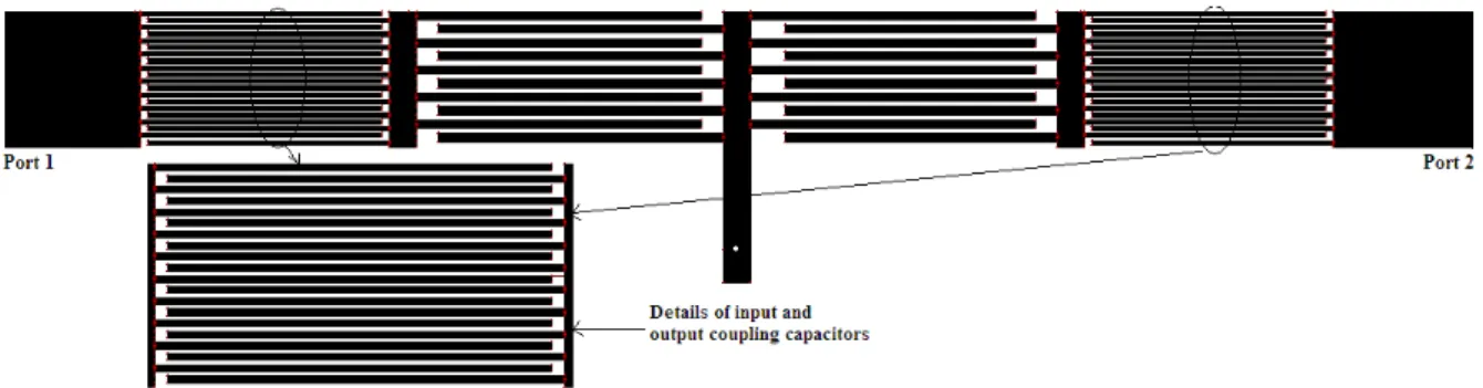
Fig. 4. Layout of the proposed 1.5 unit-cell ZOR using coupling capacitors at input and output ports.
The dimensions of input and output coupling capacitors, shown in Fig. 4 are as follows: number of interdigital fingers; 20, interdigital finger length; 8.9 mm, interdigital finger width; 0.15 mm and spacing between fingers; 0.10 mm. The required value of the bandwidth (21.33 %) of the ZOR is obtained by optimizing the various parameters (length of finger, width of the finger, spacing between the finger and the gap between the finger and feed line width) of the input and output coupling IDCs. The impedance of the transmission line of design A is found to be 77.1 , whereas for proposed design impedance is found to be 62.3 .
The dispersion diagram ( - curve) for design A, ZOR of Fig. 3 is depicted in Fig. 5. From the dispersion diagram it can be observed that the LH and RH regions for design A are
GHz f
GHz LH 1.8
2 .
1 < < and 2.0GHz <fRH<2.7GHzrespectively and also the propagation constant ( ) becomes zero at frequency 1.8 GHz, which is known as zeroth order resonance frequency (f0). Since becomes zero at resonance frequency, hence wavelength g becomes infinite, and hence the
resonant frequency of the zeroth-order mode becomes independent of the size of the resonator.
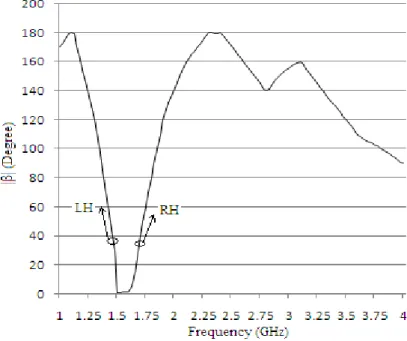
The dispersion diagram for proposed ZOR of Fig. 4 is depicted in Fig. 6. From the dispersion diagram it can be observed that the LH and RH regions for proposed ZOR are
GHz f
GHz LH 1.5
1 .
1 < < and 1.6GHz< fRH<2.4GHzrespectively and also the propagation constant ( ) becomes zero at frequency (f0), 1.5 GHz.
Fig. 6. Dispersion diagram of proposed 1.5 unit-cell ZOR.
Fig. 7. Simulated S-parameters vs. Frequency plot for design A, 1.5-unit cell ZOR
frequency of 1.8 GHz. The bandwidth and fractional bandwidth are 0.016 GHz and 0.88 % respectively. Due to this very narrow fractional bandwidth such type of conventional ZOR is not practical for the use in wireless communication systems.
The fabricated layout of the 1.5 unit-cell conventional zeroth order resonator (design A) is shown in Fig. 8. The comparative measured and simulated S-parameters vs. frequency plot is shown in Fig. 9. Fig. 9 shows that the measured zeroth order resonant frequency, return loss, insertion loss, bandwidth and fractional bandwidth are 1.8 GHz, -6.63 dB, -9.09 dB, 0.014 GHz and 0.77 % respectively.
Fig. 8. The photograph of the design A, ZOR using coupling slots at the input and output ports.
Fig. 9. Comparative measured and simulated S-parameters vs. frequency plot of the design A, ZOR.
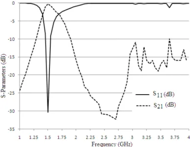
The simulated S-parameters characteristic for proposed ZOR based on coupling capacitors (Fig. 4) is computed by using full-wave electromagnetic simulator, IE3D is shown in Fig. 10. The zeroth order resonance (f0) is observed at frequency 1.5 GHz, as observable in the dispersion curve discussed in Fig. 6.
characteristics of the proposed ZOR as compared to the design A, ZOR. The bandwidth and fractional bandwidth are 0.32 GHz and 21.32 % respectively. Due to large bandwidth, such type of proposed ZOR may be useful for the applications in wireless communication systems.
Fig. 10. Simulated S-parameters vs. Frequency plot for the proposed 1.5-unit cell ZOR.
Fig. 11. The photograph of the proposed ZOR using coupling capacitors at the input and output ports.
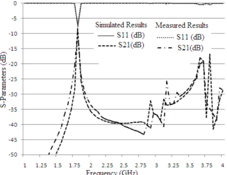
The fabricated layout of the 1.5 unit-cell proposed zeroth order resonator is shown in Fig. 11. The comparative measured and simulated S-parameters vs. frequency plot is shown in Fig. 12. Fig. 12 shows that the measured zeroth order resonant frequency, return loss, insertion loss, bandwidth and fractional bandwidth are 1.5 GHz, -26.31 dB, -0.42 dB, 0.31 GHz and 20.66 % respectively. The minor difference between the simulated and measured results can be observed in the plots of Fig. 9 and Fig. 12, because of fabrication error, mismatch between the connector and input, output transmission lines and finite ground plane. These fabricated results are in good agreements with the simulated results. All these measured and simulated results for design A, ZOR and proposed ZOR are summarized in Table I.
TABLE I. COMPARATIVE SIMULATED AND MEASURED RESULTS FOR DESIGN A, ZOR AND PROPOSED ZOR
IV. CONCLUSION
In this paper an improved novel zeroth order resonator is reported, and its simulated and measured performance is compared with the conventional previously reported zeroth order resonator. The proposed 1.5 unit-cell zeroth order resonator based on coupling capacitors is having very low measured insertion loss (-0.42 dB) at resonance frequency of 1.5 GHz as compared to the conventional 1.5 unit-cell zeroth order resonator based on coupling slots, which has the high insertion loss; -9.09 dB at the resonance frequency of 1.8 GHz. Moreover the proposed ZOR is having better return loss as compared to the conventional ZOR. A valuable improvements in the measured fractional bandwidth for proposed ZOR is also observed, which is 20.66%, as compared to the conventional ZOR, for which measured fractional bandwidth is very narrow, 0.77 %. Due to these advantages this proposed resonator profile may find applications in microwave and wireless communication.
REFERENCES
[1] C. Caloz, C.C. Chang, and T. Itoh, “Full-wave verification of the fundamental properties of left-handed materials (LHMs) in waveguide configurations,” J. App. Phys., vol. 90, no. 11, pp. 5483-5486, Dec. 2001.
1.5 Unit Cell ZOR Design A, ZOR Proposed ZOR
Simulated Results
Resonant Frequency ( )
(GHz)
1.80 1.50 BW (GHz) 0.016 0.32 FWB (%) 0.88 21.33 S11 (dB) at ( ) -7.79 -30.33
S21 (dB) at ( ) -8.19 -0.23
Measured Results
Resonant Frequency ( )
(GHz)
1.80 1.50 BW (GHz) 0.014 0.31 FWB (%) 0.77 20.66 S11 (dB) at ( ) -6.63 -26.31
formed by lattices of wires and split-ring resonators,” IEEE Trans. Antennas Propagat., vol. 51, pp. 2582–2591, Oct. 2003
[3] A. Lai, C. Caloz, and T. Itoh, “Composite right/left-handed transmission line metamaterials,” IEEE Microwave Magazine, vol. 5, no. 3, pp. 34-50, Sep. 2004.
[4] Casares-Miranda, F. P., C. Camacho Peñalosa, and C. Caloz, “High-gain active composite right/left-handed leaky-wave antenna,” IEEE Trans. Antennas Propag., vol. 54, no. 8, pp. 2292-2300, Aug. 2006.
[5] A. Lai, K. M. K. H. Leong, and T. Itoh, “Infinite wavelength resonant antennas with monopole radiation pattern based on periodic structures,” IEEE Trans. Antennas Propag., vol. 55, no. 3, pp. 868–875, Mar. 2007.
[6] R. Marque, F. Martin and M. Sorolla, Metamaterials with Negative Parameters: Theory, Design, and Microwave Applications, 1st ed.,John Wiley & Sons, Inc., Hoboken, NJ, 2008.
[7] C. Caloz and T. Itoh, Electromagnetic Metamaterials: Transmission Line Theory and Microwave Applications, 2nd ed., Wiley and IEEE Press, Hoboken, NJ, Dec. 2005.
[8] Taehee Jang, Jaehyurk Choi and Sungjoon Lim, “Compact Coplanar Waveguide (CPW)-Fed Zeroth-Order Resonant Antennas With Extended Bandwidth and High Efficiency on Vialess Single Layer,” IEEE Trans. on Antennas and Propag., vol. 59, no. 2, pp. 363-372, Feb. 2011.