doi:10.5194/ms-7-135-2016
© Author(s) 2016. CC Attribution 3.0 License.
DAS-2D: a concept design tool
for compliant mechanisms
Omer Anil Turkkan and Hai-Jun Su
Design, Innovation and Simulation Laboratory, Department of Mechanical Engineering, The Ohio State University, Columbus, OH 43210, USA
Correspondence to:Hai-Jun Su ([email protected])
Received: 29 March 2016 – Revised: 20 May 2016 – Accepted: 1 June 2016 – Published: 11 July 2016
Abstract. Compliant mechanisms utilize the deformation of the elastic members to achieve the desired motion. Currently, design and analysis of compliant mechanisms rely on several commercial dynamics and finite ele-ment simulation tools. However, these tools do not impleele-ment the most recently developed theories in compliant mechanism research. In this article, we present DAS-2D (Design, Analysis and Synthesis), a conceptual design tool which integrates the recently developed pseudo-rigid-body models and kinetostatic analysis/synthesis theo-ries for compliant mechanisms. Coded in Matlab, the software features a kinematic solver for general rigid-body mechanisms, a kinetostatic solver for compliant mechanisms and a fully interactive graphical user interface. The implementation details of all modules of the program are presented and demonstrated with four different case studies. This tool can be beneficial to classroom teaching as well as engineering practices in design of compliant mechanisms.
1 Introduction
Rigid-body mechanisms (Uicker et al., 2003) transfer motion of rigid links connected by kinematic joints. Likewise, com-pliant mechanisms (Howell, 2001) perform the same tasks via the deflections of the flexible members. It is essential dur-ing the design process to perform kinematic and static analy-sis on mechanisms to understand if displacements, velocities, and accelerations are acceptable for the desired function and to determine the required loads to accomplish the predeter-mined function. In the past two decades, three most impor-tant methods have been developed to analyze elastic defor-mation of compliant mechanisms: pseudo-rigid-body (PRB) model approach, continuum mechanics and finite element approach.
The PRB model approach substitutes compliant links with a series of (typically two to four) rigid segments joined with torsion or linear springs. Howell and Midha (Howell, 1991; Howell and Midha, 1995) had developed the earliest PRB 1R model which replaces elastic members with two rigid-body links connected with a torsion spring. “R” and “P” represent a revolute and a prismatic joint for a PRB model. PRB 1R
model also has two parametersγ andK2, characteristic
ra-dius factor and equivalent spring stiffness respectively, which needs to be tuned for different loading conditions. Saxena and Kramer (1998) improved the 1R model by switching to two linear springs to limit the change of the characteristic ra-dius factor. Su (2009) proposed a PRB-3R model that is load independent within a load range. Saggere and Kota (1999) developed a PRB-FSM (Finite-Segment) model in which the
beam is divided into (n+1)≥3 segments joined byn
tor-sional springs of stiffnessEI / l.
structures but it is not possible to analyze mechanisms that contain moving joints. Similarly, SPACAR (Jonker and Mei-jaard, 1990) is a software package for dynamic modeling and analysis of multibody flexible systems with finite element analysis.
WorkingModel 2D is a commercial software for multi-body dynamic simulation of planar physical systems. It has been often used in design and simulation of planar mech-anisms. Adams (MSC Software) is an another commercial software capable of dynamic simulation of planar mech-anisms. MATLAB’s SimMechanics toolbox is a powerful multi-body dynamics solver however the design process with block diagrams is not entirely intuitive and the toolbox lacks of proper interactivity between the user and the simulation. Yue et al. (2012) have developed virtual reality user faces that communicate with SimMechanics solver for inter-active design of planar mechanisms. Ch Mechanism Toolkit (Cheng and Trang, 2005) enables users to create and per-form kinematic analysis on rigid body mechanisms utilizing the Ch language. However, for each individual mechanism, a different class file must be prepared and kinematic equations must be manually inputted.
Given numerous advances in compliant mechanism theo-ries in the past two decades, there is no design software that is dedicated to design of compliant mechanisms. In this paper, we aim to fill this gap by developing a conceptual design tool that integrates kinetostatic analysis and synthesis theory for design of compliant mechanisms. Kinematics of rigid-body mechanisms will also be a side product of this software since they are considered as a special subset of compliant mech-anisms. The software was developed in MATLAB in order to take advantage of the built-in functions, such as nonlinear equation solvers and optimization routines. Also, the soft-ware tool has a fully interactive graphical user interface to aid users during the design process.
First section of the paper explains the theory behind the kinematic and static analysis modules of the software. Then, a detailed explanation of the implementation of these the-ories for the different analysis modules are presented with flowcharts and algorithms. An overview of the graphical user interface is given in the next section. Finally, four case stud-ies are illustrated to demonstrate and verify different analysis modules.
2 Theory and mathematical formulation
It is well known that analysis of compliant mechanisms in-volves simultaneously solving a set of kinematic equations coupled with static force equilibrium equations which are called kinetostatic (kinematic and static) equations. In this section, we present the mathematical formulation of kineto-static equations.
Z1
Z5
Z6 Z3
Z4 Z2
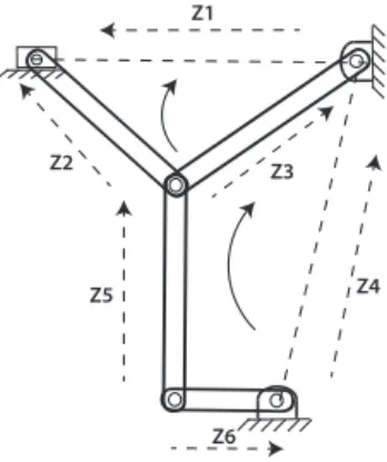
Figure 1.Two of the three available independent loops that are re-quired to analyze the mechanism are shown.
2.1 Kinematic vector loop closure equations
Complex number method is one of the most commonly used methods in kinematic analysis of rigid mechanisms:
Z=reiθ=r(cosθ+isinθ), (1)
wherei=√−1 is the complex number unit. In general, the
vector loop equation for a mechanism with l independent
closed loops can be written in the complex form:
c
X
i=1
CkiZi=0, 1≤k≤l, (2)
where coefficientCkican be−1, 0 or 1.
For instance, the mechanism shown in Fig. 1 hasl=2
in-dependent loops. The two vector loop equations are:
Z2−Z1−Z3=0, (3)
−Z6+Z5+Z3−Z4=0. (4)
Each complex equation will produce equations inxandy
di-rections, while producing four equations at total, for the mechanism shown in Fig. 1. If one link is driven, these four equations must be solved simultaneously to determine the fi-nal configuration.
2.2 The pseudo-rigid-body model for compliant links
Compliant mechanisms have at least one compliant link that can be deformed under external forces. Pseudo-rigid-body models (PRB) have been widely used in the analysis and
synthesis of compliant mechanisms. In this approach,nrigid
segments are joined with torsion and/or linear springs. Fig-ure 2 shows two examples of pseudo-rigid-body models. Several PRB models have been developed to analyze elastic members.
0.1l
0.15l
0.35l
0.40l
F
k=3.51EI/l
k=2.99EI/l
k=2.58EI/l
θ0 Φ
L
l
l l l
k=EI/l k=EI/l k=EI/l k=EI/l
M
Boundary Boundary
Figure 2.The PRB-3R model (left) and the finite segment model (right) for compliant beams.
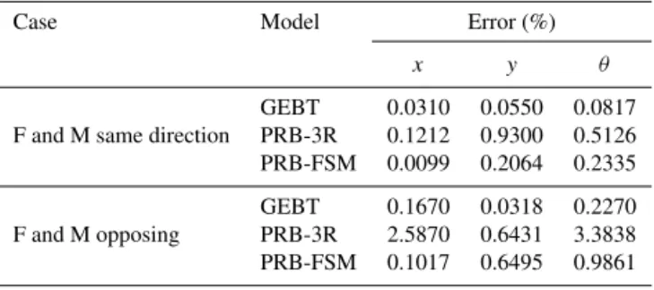
Table 1.Comparison of PRB-3R, PRB-FSM and GEBT methods versus the analytical model in static analysis of a beam.
Case Model Error (%)
x y θ
GEBT 0.0310 0.0550 0.0817 F and M same direction PRB-3R 0.1212 0.9300 0.5126 PRB-FSM 0.0099 0.2064 0.2335
GEBT 0.1670 0.0318 0.2270 F and M opposing PRB-3R 2.5870 0.6431 3.3838 PRB-FSM 0.1017 0.6495 0.9861
called a PRB matrix:
=
γ1 kex1 kθ1
. . .. . .. . .. . .. . . γn kexn kθ n
(5)
where each row represents a different segment in the
flexi-ble beam. Each row consists of length of the segmentγ, the
axial stiffness of the springkexand the magnitude of the
tor-sion spring kθ n. This representation of compliant beams is
adopted in the software and each individual flexible beam is represented with a predefined but customizable PRB matrix. Different PRB models have varying accuracies and thus, the accuracy of static analysis greatly depends on the PRB models used in the analysis. The accuracy of pseudo-rigid-body models can be illustrated with a basic example of a single beam loaded from one end and fixed to wall at the other end. The beam is discretized using 3R and PRB-FSM (11 segments) methods and compared with Bernoulli– Euler large deflection equation and GEBT. The first test case is a large force and moment acting in the same direction and the next case is an opposing force and moment. Table 1 shows good agreement between PRB models and the ana-lytical model. The error with the anaana-lytical model comes from the discretization of the compliant beam (number of segments) and the superiority of the PRB-FSM model over the PRB-3R model comes from the number of rigid-link seg-ments used in discretization of the elastic beam.
Typically, PRB models with higher number of segments yield more accurate results. PRB-FSM model with more than
ten segments will be always reasonably accurate for any compliant mechanism regardless of the loading condition. However, employing PRB-FSM model can increase the de-grees of freedom of a compliant mechanism beyond a limit where an analysis is not possible within an acceptable time frame. There exists some PRB models (Su, 2009; Yu et al., 2012) that are made of three or four segments and are very accurate for a range of loading conditions. These models pro-duce faster results without compromising the accuracy, al-though special care must be taken not to exceed the opti-mized loading limit of the PRB model. Sometimes, extension or shortening of the compliant members is necessary in order to drive a compliant mechanism and therefore, PRB models with linear springs must be employed. PRB-FSM model with linear springs will be again accurate but slow. Venkiteswaran and Su (2014) constructed a library of PRB models with lin-ear springs that had been optimized for short beams, but the accuracy of the models with more than three segments are not guaranteed for long slender beams.
2.3 Kinetostatic analysis of compliant mechanisms
Kinetostatic analysis is defined as determining the deflection of a compliant mechanism upon a given load or vice versa. Several methods exist for derivation of kinetostatic equations (coupled kinematic and static equilibrium). Direct stiffness approach (Melosh, 1963; Hughes, 2012; Ranzi et al., 2004) can be used to perform linear static analysis. This method is currently being used in static analysis of rigid-body (SAM, Rankers and Schrama, 2002) and compliant mechanisms (CoMeT, Culpepper and Kim, 2004). Although it has advan-tage of simple formulation, the stiffness approach is based on linear models and it is not accurate for large deflections.
The total work done on a mechanism is the sum of work done by external forces (forces and moments) and internal forces (springs),
W =WI+WE=U+V . (6)
Total work done on the mechanism by spring forces is the negative of the work done on the springs:
U= −
n
X
i=0
1
2kei(xi−xi0)
2 −
m
X
j=0
1
2kθj θj−θj0 2
, (7)
wherenandmare the number of linear springs and the
num-ber of torsion springs, respectively. The first sum represents the total work done by linear springs, whereas the second sum represents the work done by torsion springs.
Total work done on the system by external forces (along a
path−→r) and external moments is calculated as:
V =
l
X
i=0 ri Z
ri0
Fi·dr+ s
X
j=0 θj Z
θj0
Mjdθ, (8)
wherelandsare the number of external forces and the
num-ber of external moments, respectively. The first sum repre-sents the total work done by external forces, whereas the sec-ond sum represents the work done by external moments.
Potential energy of the system is the negative of the work
function; i.e.,E= −W= −U−V. The main principle of the
virtual work leads to
δE= δE
δq1
δq1+. . .+
δE
δqn
δqn= −δW=0. (9)
Equation (9) states that a stationary potential energy is the necessary and sufficient condition for equilibrium of a con-servative system. This means that equilibrium position (sta-tionary) point can be obtained from minimization of the po-tential energy. This optimization must be subjected to the kinematic constraint equations defined in Eq. (2). Finally, the optimization problem is mathematically formulated as:
min ψi f=
n+m
X
i=0 1
2ki(ψi−ψ0) 2
−
l
X
j=0 rj
Z
rj0 Fj·dr−
s
X
p=0 θj
Z
θp0
Mpdθ
(10)
subject tog=
c
X
i=1
CkiZi=0, (11)
where (k, ψ) equals to (ke, x) and (kθ, θ) for linear and
tor-sion springs, respectively.
Equation (10) is very similar to the minimization of po-tential energy (MinPE) method by Aten et al. (2011). MinPe method handles the external loads by adding force equilib-rium equations at the links where loads are applied. The force balance equations may bring additional optimization variables and implementation difficulties compared to the
Eq. (10). However, the MinPE method has the advantage of having the joint loading information without any further post-processing after minimization.
If the direction of a force is fixed during minimization at Eq. (10), the force integral will reduce toFx(x−x0)+Fy(y−
y0) whereFxandFy are the force magnitudes in thex and
y directions,x andy are the distance to the origin during
the optimization, andx0andy0are the initial distance to the
origin. Since−Fxx0−Fyy0is constant during minimization,
the accuracy of the optimization will not be affected if the optimization is done in one or more steps. If follower forces that change direction with the applied link exists, the force integral will be path dependent. The magnitude of all loads must be incrementally increased (Algorithm 1) in order to have better accuracy. The accuracy of the force integral will then be parallel with the number of increments. Similar to the non-follower forces, the accuracy of the moment integral is independent of the number of increments.
Algorithm 1Algorithm for incrementally increasing force
1: initial guess←starting configuration 2: power=[0,. . .,100]n
3: fori←1 tondo
4: force←(input force)×power(i)/100
5: next configuration←minimize energy (initial guess, force) 6: initial guess←next configuration
7: end for
3 Implementation
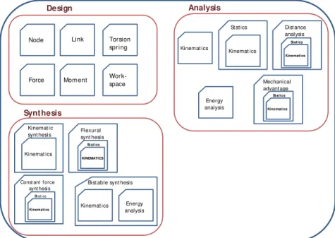
In this section, we describe the implementation details of DAS (Design, Analysis and Synthesis) 2D, a computer-aided design tool for planar compliant mechanisms. The compli-ant mechanism design software is implemented in MATLAB using object oriented programming (Fig. 3) while taking ad-vantage of the built-in nonlinear equation solver, optimizer and plotting tools. Also, graphical user interfaces have been implemented to facilitate the design process.
3.1 Graphical representation of mechanisms
Design
Node Link
Force Moment
Torsion spring
Work-space
Analysis
Kinemat ics Kinemat ics
St at ics Dist ance analysis
Mechanical advant age
Energy analysis
Synthesis
Kinemat ics Kinemat ic
synt hesis Fl exural synt hesis
Const ant f orce synt hesis
Bist able synt hesis
Kinemat ics Energy analysis
KINEMATICS St at ics
Kinematics St at ics
Kinematics St at ics
Kinematics Statics
Figure 3.DAS 2D class structure is shown. The main classes can be categorized under three different groups.
2,R R
R
1,R R
3,PR P
L1 1 2 3
4
1
2 3
4 P
R
R
R
L2
L3 1,R
2,R
3,PR L1
L3 L2
Figure 4.A slider-crank mechanism its the graph theory represen-tations: the classical graph representation (top) and the new graphi-cal representation implemented in DAS-2D.
without breaking multiple joints into binary joints. A new representation is adapted over the traditional method and in this new representation, vertices represent the nodes (or the joints) and the edges denote the links between the joints. This new representation is parallel with how individual links are stored in the software.
3.2 Kinematic analysis
The main challenge of kinematic analysis is finding the inde-pendent loops for formulating the kinematic constraint equa-tions. In the graph theory, the topology of any mechanisms can be represented with an adjacency matrix and the number of independent kinematic loops can be calculated with the Euler’s formula. Once the adjacency matrix and the number of independent kinematic loops are determined, back edges of the graph can be found by a depth first search algorithm
(Algorithm 2). The back edges are then converted to base cy-cles by adding the parent nodes until the start and end nodes are the same.
Algorithm 2Depth first search for finding the back edges of a graph.
1: startNode←Any node in the graph 2: currentNode←startNode.child(1) 3: Parent(currentNode)←startNode 4: Visited(currentNode)←1 5: whilecurrentNode6=startNodedo
6: ifall currentNode.childs visited from currentNodethen
7: currentNode←Parent(currentNode) 8: else
9: fori=1 to #currentNode.childsdo
10: if Visited(currentNode.child(i))then
11: currentNode-currentNode.child(i)←backedge
12: else
13: Parent(currentNode.child(i))←currentNode 14: Visited(currentNode.child(i))←1
15: currentNode←currentNode.child(i)
16: break for loop
17: end if
18: end for
19: end if
20: end while
After all independent kinematic loops are found, nonlinear kinematic equations of the mechanism can be derived. The
kinematic equation for theith link can be written as:
− →
Mz
Fy
Fx
Transform compliant links
• Establish origin • Move forces • Adjacency matrix
• Find loops
• Find path between the origin and forces Design
• Kinematic equations • Force kinematic
equations
Optimize total energy
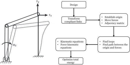
Figure 5.The schematic view (left) and flowchart (right) of the static force analysis problem.Fx,FyandMzrepresent known loads exerting on the mechanism.
whereZi0andλi are constant design parameters for the link
andf is a function for which input is the unknown
parame-ter(s) needed to define the link. As an example, for a binary link with two pin joints, the termZi0is zero,λi =riis length
of the link andf=(cosθi,sinθi)T whereθiis the link angle.
Following this notation, for a mechanism withnlinks and
l independent loops, the kinematic constraint equations can
be systematically derived asnvector equations or 2nscalar
equations:
n
X
i=1
CkiZi=
0 0
, 1≤k≤l, (13)
where coefficientCkican be−1, 0 or 1.
By applying Eq. (13), kinematic equations will be formed and they can be solved simultaneously using a nonlinear equation solver with the number of inputs equal or less than the degrees of freedom of the mechanism. The interactive kinematic analysis capabilities of the software was previ-ously demonstrated at Turkkan and Su (2014).
3.3 Static (force) analysis
Static force analysis can be described as determining the re-lationship between the external loading and the deflection of the compliant mechanism. Figure 5 illustrates the schematic view of the static analysis problem and the flowchart of the static solver. The module starts with converting compliant links into a series of rigid-body links using a pseudo-rigid-body model as described earlier. Then, kinematic equations are derived based on the independent kinematic loops. A breadth-first search algorithm is used to determine the deflec-tion of the point where the external force is applied. Finally, the optimization in Eq. (10) and Algorithm 1 are employed in the last optimization step to determine the resulting con-figuration of the mechanism.
3.4 Distance analysis
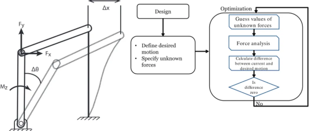
Contrary to the static force analysis, the distance analysis de-fined as determining the required load(s) that will result in a prescribed deformation. As shown in Fig. 6, the desired de-formation can be translation of a node or rotation of a link. The output of this module will be the magnitudes of the un-known loads.
After designing a mechanism, the desired motion of a node or a link and unknown loads on the mechanism are de-fined. Then, the magnitudes of unknown loads are obtained by an optimization process which minimizes the difference between current deformation and the desired deformation.
3.5 Mechanical advantage analysis
Mechanical advantage is defined as the ratio of the output
force/moment over the input force/moment, e.g. Mo/Mi
for the case in Fig. 7. It is one of the most important de-sign criterion in compliant mechanisms. Mechanical advan-tage analysis is to find the balancing load for a given input load. For a mechanism, one load is selected as the input force and another load is selected as the output force. The input force is assumed to be an unit load. Then, an optimization process shown in Fig. 7 is initialized. At each optimization step, magnitude of the output force is guessed and resulting configuration is calculated via force analysis. The displace-ment of the nodes are minimized to zero in order to ensure that the mechanism stays at the initial design configuration.
3.6 Load and energy curve plotting
Mz Fy
Fx
Δx
Δθ
• Define desired motion • Specify unknown
forces Design
Guess values of un kn own forces
Force an alysis
Calculate difference between current and desired m otion
Is difference
zero
No Optimization
Figure 6.The schematic view (left) and flowchart (right) of the distance analysis problem.1xor1θ is the given input motion and the magnitudes of unknown loads (Fx,FyandMz) are the desired outputs of the module.
Mi
Mo
• Select the input
force
• Select the output
force Design
Guess the value of output force
Force an alysis
Calculate difference between current and
design nodes
Is difference
zero
No Optimization
Figure 7.The schematic view (left) and flowchart (right) of mechanical advantage analysis problem.Miis the input moment andMois the output force. The module will return the ratio ofMo/Mi.
target displacement (link rotation or a slider displacement). At each iteration, the corresponding link angle or slider po-sition is fixed and the potential energy of the system is mini-mized while subjected to kinematic constraints of the mech-anism. The total potential energy is calculated and finally, torque is calculated by taking derivative of the potential en-ergy stored in springs with a central finite difference method.
Algorithm 3 Algorithm for obtaining torque and energy within a specified range
1: distance=[0,. . .,100]n 2: fori←1 tondo
3: Link Angle(Slider Position)←angle(distance)[i]
4: minimize total potential energy (Subject to kinematic equa-tions)
5: calculate Energy(i)
6: Torque(i)←derivative of Energy(i) 7: end for
3.7 Graphical user interfaces
To expedite the design process, a graphical user interface has been developed with MATLAB and interfaces for the some of the design and analysis modules are shown in Fig. 8. Panel (a) shows a step in the design process. The PRB model of a compliant link can be specified using a dedicated user interface shown in panel (b). Panel (c) shows the kinematic analysis. Users can interact with a mechanism via mouse op-erations (dragging, clicks) which trigger the kinematic anal-ysis class. Similarly, a mechanism can be animated within a range of input values using this module. Panels (d), (e) and (f) display the load analysis, distance analysis and energy anal-ysis interfaces, respectively.
4 Case studies
(a)
(b)
(c)
(d)
(e)
(f)
Figure 8.The graphic user interface for the six modules:(a)design,(b)PRB Models,(c)kinematic analysis,(d)load analysis,(e)distance analysis and(f)energy analysis. The software can be downloaded at DISL Software (2016).
4.1 Parallelogram flexure mechanism
To test the static solver, we give an example of a parallel-ogram flexure mechanism which consists of two identical
compliant beams (length=100 mm, in-plane width=1 mm,
out-plane depth=20 mm,E=72 GPa), as shown in Fig. 9.
Normalized (dimensionless) loads exerting on the rigid link are defined as:
fx=
FxL2
E I fy=
FyL2
E I mz=
MzL
E I . (14)
Static analysis is performed on the mechanism for a large range of load magnitude (fx,fy,mz∈ [1,10]). Two different
PRB models are employed and the two analysis results are compared with Beam Constraint Model (BCM) Awtar et al. (2006) analytical model and the Abaqus FEM software. Fig-ure 9 shows the software output when normalized loads are
equal to 10 and it can be seen that quite largeydisplacement
(≈28 mm) of the rigid link is present. Therefore, this range
of normalized loads are satisfactory in investigating accuracy of the software for small and large displacements.
Figure 9.The two PRB models used (left) and the software output of the deformation of the flexure mechanism (right).
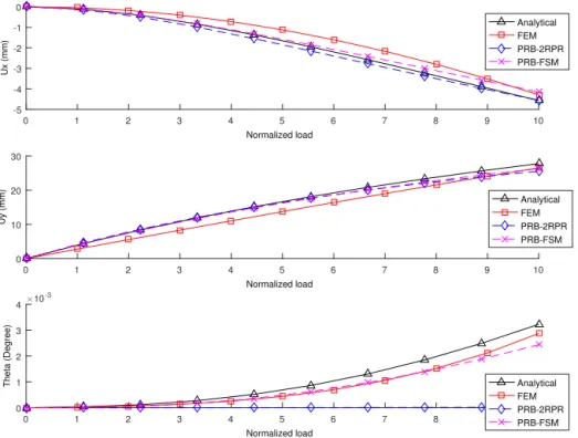
Figure 10 shows the complete comparison of x, y
nor-0 1 2 3 4 5 6 7 8 9 10
Normalized load
-5 -4 -3 -2 -1 0
Ux (mm)
Analytical FEM PRB-2RPR PRB-FSM
0 1 2 3 4 5 6 7 8 9 10
Normalized load
0 10 20 30
Uy (mm)
Analytical FEM PRB-2RPR PRB-FSM
0 1 2 3 4 5 6 7 8 9 10
Normalized load
0 1 2 3 4
Theta (Degree)
#10-3
Analytical FEM PRB-2RPR PRB-FSM
Figure 10.Comparison of the software results with analytical model (BCM) and ABAQUS software. Magnitudes offx,fy andmx are equal at each step and they are simultaneously incremented between zero and ten.
malized loads (until 6–7), the PRB-FSM (n=11) model
fol-lows the analytical model very closely, whereas x, y
dis-placements converge to the Abaqus results as the magnitude of loads increases. PRB-2(RP)R model accompany the
ana-lytical model throughout the whole load range inxandy
dis-placements but fails to capture the rotation of the rigid link. PRB-FSM model closely follows the Abaqus results in the rotation of the rigid link.
4.2 Compound multibeam parallelogram mechanisms
Compound multibeam parallelogram mechanisms (CMPM) are composed of multiple parallelogram flexure mechanisms. Hao and Li (2015, 2016) developed an analytical model for nonlinear deformation of CMPMs. The study found out that the configuration at Fig. 11 has nonlinear displacement char-acteristics at the primary direction due to load-stiffening ef-fect. Since lengths of the compliant members must increase during deformation, only PRB models with linear springs can be employed during analysis. The geometric properties of a
compliant member are as follows: in-plane width =1 mm,
out-plane depth =10 mm and length =40 mm. The
elas-tic modulus and Poisson’s ratio of the elaselas-tic members are 2.3 GPa and 0.37, respectively. The force is applied in the primary direction at the rigid link of length 30 mm.
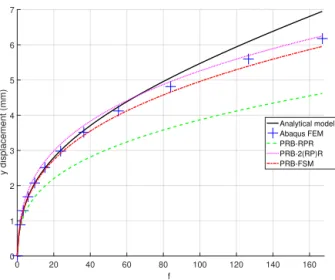
Three different PRB models (PRB-RPR, PRB-2(PR)R, PRB-FSM with 10 springs; Table A1) are employed in the analysis and the results are compared with analytical model
Figure 11.A typical compound multibeam parallelogram mecha-nism loaded at the primary direction.
0 20 40 60 80 100 120 140 160 fy
0 1 2 3 4 5 6 7
y displacement (mm)
Analytical model Abaqus FEM PRB-RPR PRB-2(RP)R PRB-FSM
Figure 12. Comparison of the software results with analytical model (Hao and Li, 2015) and ABAQUS software.fy is normal-ized as shown in Eq. (14).
4.3 Distance analysis
We considered a fully compliant bistable mechanism (Wilcox and Howell, 2005) shown in Fig. 13 to test the dis-tance analysis module. The long beams are approximated with PRB models that contain three linear springs and two torsion springs. The linear spring is utilized to capture the lin-ear elongation of the long beams. The short compliant beams are represented with the PRB-3R model. The cross sections of the short and long elastic beams are comparable in size but the elastic modulus of the short beam is approximately 30 times larger resulting in short beams being much stiffer than the longer beams. The length of the center rigid link is 30 mm.
The target vertical displacement of the mechanism is set to
y∈ [1,10]mm and three different PRB models (PRB-RPR,
PRB-2(PR)P, PRB-2(RP)R; Table A1) were chosen to repre-sent the long compliant beam. Figure 13 also shows the anal-ysis results compared with the Abaqus simulation result. The newly developed model, PRB-2(RP)R, is very close to the Abaqus result. Although the other two models come closer to the Abaqus result for large deflections, they fail to capture the general trend in the Abaqus result.
4.4 Load and energy curve plotting
A compliant four bar bistable mechanism (Fig. 14) with a
flexible link was designed and 90◦clockwise rotation of the
crank link was specified as the target motion. The lengths of the links are 15, 37.0842 and 43.294 mm for the crank, cou-pler and compliant links, respectively. The width and depth of the compliant beam is 1.5 and 5 mm, respectively. Steel
(E=207 GPa) was chosen as the design material of the
com-pliant beam.
Figure 14 shows the comparison of the output of the pro-gram compared with the Adams software. The PRB-FSM (10 torsion springs) model was used to represent the elas-tic link. The difference between the torques for the two soft-wares is around 6 % for the negative peak and 10 % for the positive peak. Since the location of the stable and unstable points is essentially a kinematics problem, (un)stable points happen at same angle values in the both cases. Also, it was found that the torque values are highly sensitive to the mesh of the elastic link in the Adams. Although not shown, if the same PRB model is implemented in Adams, both tools give the exact same results.
5 Conclusions
(a) (b)
(c) (d)
Linear spring Torsion spring
Compliant Rigid
(e)
PRB-RPR Model
PRB-2(RP)P Model PRB-2(RP)R Model
Displacement (mm)
0 1 2 3 4 5 6 7 8 9 10 11 12
F
o
rc
e
(
N
)
0 0.5 1 1.5 2
2.5 Comparison of PRB Models with the Abaqus Software
Abaqus PRB-RPR PRB-2(RP)P PRB-2(RP)R
Figure 13.(a)A schematic view of the compliant mechanism consisting of four identical limbs each of which has two compliant beams joined with a rigid link. Panels(b),(c)and(d)show the three different PRB models (PRB-RPR, PRB-2(PR)P, PRB-2(RP)R respectively). Comparison of the PRB model results with the Abaqus FSM result is shown in the panel(e).
Appendix A: PRB models
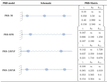
Table A1.List of the PRB Matrix values for the PRB Models used in the paper. First row of the PRB matrix of a PRB-FSM model with
ntorsion springs is
0.5/n∞ ∞
, the last row (n+1th) is
1/n n∞
and the remaining rows are 1/n n∞
. If extension effect is desired,
kexwill be 2n, 2nandnfor the first, the last and the remaining rows of the PRB Matrix of the PRB-FSM model withntorsion springs, respectively. The parameters of the PRB-RPR and PRB-2(PR)P are obtained from Venkiteswaran and Su (2014) which were optimized for short Timoshenko type beams.
PRB model Schematic PRB-Matrix
PRB-3R
γ kθ kex
0.10 ∞ ∞
0.350 3.50 ∞
0.40 2.990 ∞
0.150 2.580 ∞
PRB-RPR
γ kθ kex
0.167 ∞ ∞
0.666 2.180 1.250
0.167 2.180 ∞
PRB-2(RP)P
γ kθ kex
0.142 ∞ 1.720 0.637 2.350 3.640
0.221 1.710 0.679
PRB-2(RP)R
γ kθ kex
0.108 ∞ ∞
0.385 4.235 4.019
0.353 3.565 0.4
0.154 3.564 ∞
Acknowledgements. This material is based upon work supported by National Science Foundation under Grant No:CMMI-1144022 and CMMI-1161841 and the Air Force Office of Scientific Re-search under contract AFOSR FA9550-12-1-0070. Any opinions, findings, and conclusions or recommendations expressed in this material are those of the author(s) and do not necessarily reflect the views of the funding agencies.
Edited by: G. Hao
Reviewed by: G. Chen and two anonymous referees
References
Aten, Q. T., Zirbel, S. A., Jensen, B. D., and Howell, L. L.: A Nu-merical Method for Position Analysis of Compliant Mechanisms With More Degrees of Freedom Than Inputs, J. Mech. Design, 133, 061009–061009, doi:10.1115/1.4004016, 2011.
Awtar, S. and Sen, S.: A generalized constraint model for two-dimensional beam flexures: Nonlinear strain energy formulation, J. Mech. Design, 132, 081009, doi:10.1115/1.4002006, 2010. Awtar, S., Slocum, A. H., and Sevincer, E.: Characteristics of
Beam-Based Flexure Modules, J. Mech. Design, 129, 625–639, doi:10.1115/1.2717231, 2006.
Chen, D.-Z. and Lin, T.-W.: Dynamic analysis of geared robotic mechanisms using graph theory, J. Mech. Design, 120, 241, doi:10.1115/1.2826964, 1998.
Cheng, H. H. and Trang, D. T.: Object-oriented interactive mechanism design and analysis, Eng. Comput., 21, 237–246, doi:10.1007/s00366-005-0008-4, 2005.
Culpepper, M. L. and Kim, S.: A Framework and Design Sythesis Tool Used to Generate, Evaluate and Optimize Compliant Mech-anism Concepts for Research and Education Activities, ASME 2004 International Design Engineering Technical Conferences and Computers and Information in Engineering Conference, 2, 1583–1588, doi:10.1115/DETC2004-57606, 2004.
DISL Software: DAS 2D, available at: http://www. compliantanalysis.com, last access: 27 June 2016, 2016. Dobrjanskyj, L. and Freudenstein, F.: Some Applications of Graph
Theory to the Structural Analysis of Mechanisms, J. Manuf. Sci. E.-T. ASME, 89, 153–158, doi:10.1115/1.3609988, 1967. Freudenstein, F. and Maki, E.: The creation of mechanisms
accord-ing to kinematic structure and function, Environment and Plan-ning B, 6, 375–391, doi:10.1068/b060375, 1979.
Hao, G. and Li, H.: Nonlinear Analytical Modeling and Character-istic Analysis of a Class of Compound Multibeam Parallelogram Mechanisms, Journal of Mechanisms and Robotics, 7, 041016, doi:10.1115/1.4029556, 2015.
Hao, G. and Li, H.: Extended Static Modeling and Analysis of Com-pliant Compound Parallelogram Mechanisms Considering the Initial Interna Axial Force, Journal of Mechanisms and Robotics, 8, 041008, doi:10.1115/1.4032592, 2016.
Howell, L. L.: The Design and Analysis of Large-deflection Mem-bers in Compliant Mechanisms, PhD thesis, Purdue University, West Lafayette, Indiana, 1991.
Howell, L. L.: Compliant mechanisms, Wiley-Interscience, USA, available at: https://books.google.de/books?hl, last access: 27 June 2016, 2001.
Howell, L. L. and Midha, A.: Parametric Deflection Ap-proximations for End-Loaded, Large-Deflection Beams in
Compliant Mechanisms, J. Mech. Design, 117, 156–165, doi:10.1115/1.2826101, 1995.
Hughes, T. J.: The finite element method: linear static and dynamic finite element analysis, Courier Dover Publications, USA, 2012. Jesús Cervantes-Sánchez, J., Rico-Martínez, J. M., Pacheco-Gutiérrez, S., and Cerda-Villafaña, G.: Static analysis of spatial parallel manipulators by means of the principle of virtual work, Robot. Cim.-Int. Manuf., 28, 385–401, doi:10.1016/j.rcim.2011.11.002, 2012.
Jonker, J. B. and Meijaard, J. P.: SPACAR – Computer program for dynamic analysis of flexible spatial mechanisms and ma-nipulators, in: Multibody systems handbook, Springer, 123–143, doi:10.1007/978-3-642-50995-7_9, 1990.
Ma, F. and Chen, G.: Modeling Large Planar Deflections of Flex-ible Beams in Compliant Mechanisms Using Chained Beam-Constraint-Model, Journal of Mechanisms and Robotics, 8, 021018, doi:10.1115/1.4031028, 2015.
Melosh, R. J.: Basis for derivation of matrices for the direct stiff-ness method, AIAA Journal, 1, 1631–1637, doi:10.2514/3.1869, 1963.
MSC Software: Adams, available at: http://www.mscsoftware.com/ product/adams, last access: 27 June 2016.
Paul, B.: Kinematics and Dynamics of Planar Machinery, Prentice-Hall, USA, 1979.
Petri, P. A.: A continuum mechanic design aid for non-planar com-pliant mechanisms, PhD thesis, Massachusetts Institute of Tech-nology, available at: http://dspace.mit.edu/handle/1721.1/8136, last access: 27 June 2016, 2002.
Pillardy, J., Czaplewski, C., Liwo, A., Lee, J., Ripoll, D. R., Ka´zmierkiewicz, R., Ołdziej, S., Wedemeyer, W. J., Gibson, K. D., Arnautova, Y. A., Saunders, J., Ye, Y.-J., and Scheraga, H. A.: Recent improvements in prediction of protein structure by global optimization of a potential energy function, P. Natl. Acad. Sci. USA, 98, 2329–2333, doi:10.1073/pnas.041609598, 2001. Rankers, A. M. and Schrama, H. W.: SAM: Simulation
and Analysis of Mechanisms, in: ASME 2002 Interna-tional Design Engineering Technical Conferences and Com-puters and Information in Engineering Conference, pp. 1383–1387, American Society of Mechanical Engineers, available at: http://proceedings.asmedigitalcollection.asme.org/ proceeding.aspx?articleid=1584486, last access: 27 June 2016, 2002.
Ranzi, G., Bradford, M. A., and Uy, B.: A direct stiffness analysis of a composite beam with partial interaction, Int. J. Numer. Meth. Eng., 61, 657–672, doi:10.1002/nme.1091, 2004.
Reddy, J. N.: Energy Principles and Variational Methods in Applied Mechanics, John Wiley & Sons, USA, 2002.
Saggere, L. and Kota, S.: Synthesis of Planar, Compliant Four-Bar Mechanisms for Compliant-Segment Motion Generation, J. Mech. Design, 123, 535–541, doi:10.1115/1.1416149, 1999. Saxena, A. and Kramer, S. N.: A Simple and Accurate Method for
Determining Large Deflections in Compliant Mechanisms Sub-jected to End Forces and Moments, J. Mech. Design, 120, 392– 400, doi:10.1115/1.2829164, 1998.
Shi, P. and McPhee, J.: Dynamics of Flexible Multibody Systems Using Virtual Work and Linear Graph Theory, Multibody Syst. Dyn., 4, 355–381, doi:10.1023/A:1009841017268, 2000. Su, H.-J.: A Pseudorigid-Body 3R Model for Determining
Journal of Mechanisms and Robotics, 1, 021008–021008, doi:10.1115/1.3046148, 2009.
Turkkan, O. A. and Su, H.-J.: A Unified Kinetostatic Analysis Framework for Planar Compliant and Rigid Body Mech-anisms, in: ASME 2014 International Design Engineering Technical Conferences and Computers and Information in Engineering Conference, American Society of Mechanical Engineers, V05BT08A090–V05BT08A090, available at: http://proceedings.asmedigitalcollection.asme.org/proceeding. aspx?articleid=2090986, last access: 27 June 2016, 2014. Uicker, J. J., Pennock, G. R., Shigley, J. E., and Mccarthy, J. M.:
Theory of machines and mechanisms, Oxford University Press New York, available at: http://www.lavoisier.fr/livre/notice.asp? ouvrage=1148142, last access: 27 June 2016, 2003.
Venkiteswaran, V. K. and Su, H.-J.: A parameter optimiza-tion framework for determining the pseudo-rigid-body model of cantilever-beams, Precis. Eng., 40, 46–54, doi:10.1016/j.precisioneng.2014.10.002, 2014.
Wilcox, D. and Howell, L.: Fully compliant tensural bistable mi-cromechanisms (FTBM), J. Microelectromech. S., 14, 1223– 1235, doi:10.1109/JMEMS.2005.859089, 2005.
Xiangzhou, Z., Yougao, L., Zhiyong, D., and Hongzan, B.: Statics of rotational 3-UPU parallel mechanisms based on principle of virtual work, in: IEEE International Conference on Robotics and Biomimetics, Sanya, China, 2007, ROBIO 2007, 1954–1959, doi:10.1109/ROBIO.2007.4522466, 2007.
Yu, W. and Blair, M.: GEBT: A general-purpose nonlinear analy-sis tool for composite beams, Compos. Struct., 94, 2677–2689, doi:10.1016/j.compstruct.2012.04.007, 2012.
Yu, Y.-Q., Feng, Z.-L., and Xu, Q.-P.: A pseudo-rigid-body 2R model of flexural beam in compliant mechanisms, Mech. Mach. Theory, 55, 18–33, doi:10.1016/j.mechmachtheory.2012.04.005, 2012.
Yue, C., Su, H.-J., and Ge, Q. J.: A hybrid computer-aided linkage design system for tracing open and closed pla-nar curves, Comput. Aided Design, 44, 1141–1150, doi:10.1016/j.cad.2012.06.004, 2012.