The in-flight blackbody calibration system for the GLORIA
interferometer on board an airborne research platform
F. Olschewski1, A. Ebersoldt2, F. Friedl-Vallon2, B. Gutschwager3, J. Hollandt3, A. Kleinert2, C. Monte3, C. Piesch2, P. Preusse4, C. Rolf1,4, P. Steffens1, and R. Koppmann1
1Physics Department, University of Wuppertal, 42097 Wuppertal, Germany 2Karlsruhe Institute of Technology, 76344 Eggenstein-Leopoldshafen, Germany 3Physikalisch-Technische Bundesanstalt, 10587 Berlin, Germany
4Research Centre Juelich GmbH, 52428 Juelich, Germany
Correspondence to:F. Olschewski ([email protected])
Received: 21 March 2013 – Published in Atmos. Meas. Tech. Discuss.: 20 June 2013 Revised: 26 September 2013 – Accepted: 4 October 2013 – Published: 12 November 2013
Abstract. The Gimballed Limb Observer for Radiance Imaging of the Atmosphere (GLORIA) is a prototype of an imaging Fourier Transform Spectrometer (FTS) for PRE-MIER, a former candidate mission for ESA’s Earth Explorer 7. GLORIA is deployed on board various research aircraft such as the Russian M55 Geophysica or the German HALO. The instrument provides detailed infrared images of the Up-per Troposphere/Lower Stratosphere (UTLS) region, which plays a crucial role in the climate system. GLORIA uses a two-dimensional detector array for infrared limb observa-tions in emission and therefore needs large-area blackbody radiation sources (126 mm×126 mm) for calibration.
In order to meet the highly demanding uncertainty require-ments for the scientific objectives of the GLORIA missions and due to the sophisticated tomographic evaluation scheme, the spatial distribution of the radiance temperature of the blackbody calibration sources has to be determined with an uncertainty of about 0.1 K. Since GLORIA is exposed to the hostile environment of the UTLS with mutable low temper-ature and pressure, an in-flight calibration system has to be carefully designed to cope with those adverse circumstances. The GLORIA in-flight calibration system consists of two identical weight-optimised high-precision blackbody radia-tion sources, which are independently stabilised at two dif-ferent temperatures. The two point calibration is in the range of the observed atmospheric infrared radiance emissions with 10 K below and 30 K above ambient temperature, re-spectively. Thermo-Electric Coolers are used to control the temperature of the blackbody radiation sources offering the
advantage of avoiding cryogens and mechanical coolers. The design and performance of the GLORIA in-flight calibration system is presented. The blackbody calibration sources have been comprehensively characterised for their spatially (full aperture) and spectrally (7 to 13 µm) resolved radiation prop-erties in terms of radiance temperatures traceable to the In-ternational Temperature Scale (ITS-90) at the Physikalisch-Technische Bundesanstalt (PTB), the national metrology in-stitute of Germany.
1 Introduction
The Gimballed Limb Observer for Radiance Imaging of the Atmosphere (GLORIA) is an airborne imaging Fourier Transform Spectrometer (FTS) deployed in the belly pod of the new German research aircraft HALO as well as on board the high-flying Russian research plane M55 Geophys-ica (Riese et al., 2014; Friedl-Vallon et al., 2014). It is the first instrument that utilises the infrared limb-imaging tech-nique (Riese et al., 2005; Friedl-Vallon et al., 2006) for trace gas measurements in the Upper Troposphere/Lower Strato-sphere (UTLS) region with unprecedented three-dimensional spatial resolution.
2010; Riese et al., 2012). Gettelman et al. (2011) state that this region exhibits complex dynamical, radiative, and chem-ical characteristics that place stringent spatial and temporal requirements on observing and modelling system. Dynam-ical processes such as stratosphere–troposphere exchange (STE) affect both the lowermost stratosphere (LMS) as well as the upper troposphere. Quantifying those processes that control the UTLS composition therefore represents an in-dispensable task (Riese et al., 2012). Important greenhouse gases such as water vapour and ozone, with steep spatial gra-dients in the UTLS, show large spatial and temporal variabil-ity as a result of STE (e.g. Stevenson et al., 2006; Ploeger et al., 2011). In particular, three-dimensional fields of wa-ter vapour, ozone, transport tracers, and chemically active species with high vertical (few 100s m) and horizontal res-olution (few 10s km) as well as low uncertainties are manda-tory to quantify physical and chemical processes controlling the composition and structure of the UTLS.
To achieve this objective, GLORIA uses a two-dimensional detector array for detailed infrared limb obser-vations in emission. The detector array consists of 256×256 individual detector pixels and can be commanded to read-out sub-frames. Up to 128×128 pixels are used by the Michel-son FTS providing over 16 000 simultaneous spectrally re-solved limb views. This allows for measurements of atmo-spheric temperature fields, clouds parameters, aerosols, wa-ter vapour, ozone, and about ten other trace species. GLORIA is a prototype of an imaging FTS for a space instrument and serves as proof of concept for the InfraRed Limb Sounder of PREMIER, one former candidate of ESA’s future Earth Ex-plorer 7 mission (e.g. ESA, 2008, 2012; Preusse et al., 2009). The calibration of infrared sounding instruments is al-ways a major challenge especially for air- or space-borne ex-periments when in-flight calibration becomes necessary. As useful atmospheric measurements always depend highly on a well performed radiometric calibration, every effort should be made to create the most precise and reliable in-flight cali-bration sources. Due to the variable environmental conditions inside the instrument compartment of the aircraft it is not suf-ficient to calibrate the instrument on the ground only. Since GLORIA is exposed to the hostile environment of the UTLS at different flight altitudes with mutable low temperature and pressure (T∼ −50◦C,p <200 hPa), the in-flight calibration system has to be carefully designed to cope with those ad-verse circumstances. Additional restrictions like weight lim-itations and power restraints are implied.
This paper describes the design and performance of the GLORIA in-flight calibration system, which has been com-prehensively characterised for its spatially (full aperture) and spectrally (7 to 13 µm) resolved radiation properties in terms of radiance temperature traceable to the International Tem-perature Scale (ITS-90) at the Physikalisch-Technische Bun-desanstalt (PTB), the national metrology institute of Ger-many. The blackbody radiation sources were tested under lab conditions as well as in a climatic and environmental test
chamber in order to verify their performance in various at-mospheric environments.
2 The GLORIA instrument
2.1 Instrument description
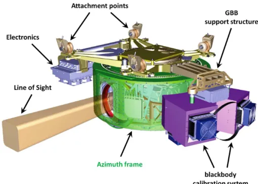
GLORIA is a joint project of Research Centre Juelich and Karlsruhe Institute of Technology, Germany. The GLORIA instrument concept is illustrated in Fig. 1. The heart of the GLORIA instrument is an imaging Michelson FTS operat-ing in the infrared spectral region from 770 to 1400 cm−1 (Friedl-Vallon et al., 2006). It delivers spectrally resolved im-ages of the Earth’s limb with a vertical and horizontal field-of-view (FOV) of 4.07◦×4.07◦ covering tangent altitudes from about 4 km to flight level. Depending on the scientific goals of a flight, the horizontal detector range and thus the number of pixels used may be reduced, allowing for faster interferogram acquisition. The spectral resolution is adjusted to two different measuring modes: 1.25 cm−1for the dynam-ics mode and 0.1 cm−1for the chemistry mode, respectively. The chemistry mode at full spectral resolution is designed to gain a maximum number of trace gas species. For the dynamics mode, the spectral resolution is reduced allowing for a higher measurement frequency. Thus small-scale atmo-spheric features can be better resolved.
A two-lens aspheric optics with a beam diameter of ap-proximately 36 mm is used to project the atmospheric ra-diation field onto the two-dimensional detector array. The detector module consists of the detector array (High Speed MCT 256×256 LW IDCA) mounted in a dewar with an in-tegrated Stirling cooler. Readout electronics digitalizes the data and feeds them into a serial data stream. A typical set-up for atmospheric measurements comprises of 128×128 pixels (vertical×horizontal), providing more than 16 000 si-multaneous interferograms in less than 20 s.
The gimballed mount, which stabilises the line-of-sight (LOS) during flight, also allows for pointing the LOS at az-imuth angles between 45 and 135◦with respect to the flight direction. This is essential for the tomographic retrieval ap-proach in order to acquire three-dimensional images of at-mospheric features (Ungermann et al., 2011). The gimbal’s agility and the manoeuvrability of the instrument is also used to align the FTS with the in-flight blackbody calibra-tion sources of GLORIA.
2.2 Calibration requirements
Fig. 1.Gimbal mounted GLORIA instrument with in-flight blackbody calibration system.
of less than 3 %. The target requirement for the GLORIA in-strument is a standard uncertainty of less than 1 % assuming that the statistical uncertainty (type A) (see ISO/IEC, 2008) of the measured spectra is significantly below 1 % and there-fore the total uncertainty of the spectral radiance results only from systematic (type B) (see ISO/IEC, 2008) and statistical uncertainties of the instrument calibration. This drives the re-quirements for the design of the in-flight blackbody calibra-tion system and the calibracalibra-tion procedure in respect of spec-tral radiance uncertainties and radiance temperature mea-surements traceable to the International Temperature Scale (ITS-90). In this section, the requirements for the blackbody radiation sources in terms of temperature, temperature gra-dients, and emissivity are described and technical limitations are discussed.
Assuming the GLORIA measurement system has a linear response, only two calibration measurements using black-body radiation sources at two different well-defined tem-peratures in the range of the atmospheric infrared radiance emissions are needed in order to radiometrically calibrate the GLORIA instrument including an offset correction. The transfer of the measured atmospheric spectra into atmo-spheric spectral radiance is given in Eq. (1):
La =Sa·
Bh−Bc Sh−Sc
| {z }
gain −
Sc·
Bh−Bc Sh−Sc
−Bc
| {z }
offset
(1)
withL: spectral radiance, S: measured spectrum, B: spec-tral radiance of blackbody (Planck function), a: atmospheric, h: hot blackbody, c: cold blackbody.
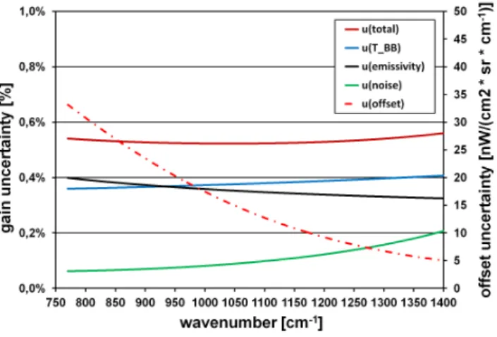
Fig. 2. Radiance uncertainty (gain and offset) according to requirements.
eliminated in order to use the upward measurement for cal-ibration. For GLORIA, the conditions are even worse since the minimal zenith angle is 80◦ due to the location inside the instrument compartment of the aircraft and therefore the optical path through the atmosphere is much longer leading to a much higher atmospheric signal. As reference measure-ments with virtually zero radiance input are not possible, the offset has to be determined by extrapolation of two black-body calibration measurements: the larger the extrapolation, the larger the offset uncertainty (uoff).
Optimising radiometric accuracy and feasibility, the fol-lowing requirements have been established for the calibration system: the uncertainty in determination of the optical sur-face temperature shall be less than 100 mK with a short term temperature stability better than 25 mK min−1. The emissiv-ity needs to be better than 0.997 in the spectral range from 7 to 13 µm while the temperature of the cold blackbody (GBB-C) is at least 10 K below ambient temperature. The temperature difference between the two calibration sources shall be at least 40 K.
The temperature uncertainty (uT) of less than 100 mK in-cludes the uncertainty of the temperature measurement by platinum resistance thermometers (PRTs), thermal gradients between the temperature sensors and the optical surface, and thermal inhomogeneities within the effective area seen by the instrument. The relatively moderate requirement for the cold blackbody being operated only 10 K below ambient temper-ature is accounted for the risk of ice deposition on the opti-cal surface of the blackbody opti-calibration sources which could drastically change the emissivity and the radiance tempera-ture. This in turn also determines the reasonable temperature difference between the two calibration sources, because the hot blackbody should not produce a much higher photon load than the atmospheric signal in order not to overload the de-tector. Since the offset determination by extrapolation of the two calibration measurements implies a troublesome uncer-tainty, an additional “quasi deep space” measurement should
Table 1.Technical specifications for the GLORIA in-flight black-body calibration system.
Optical surface 126 mm×126 mm
GBB-C temperature = ambient temperature−10 K GBB-H temperature = ambient temperature+30 K Temperature uncertainty <0.1 K
Emissivity >0.997 Spatial temperature inhomogeneity ≤0.15 K Temperature stability ≤0.025 K min−1
be established. Based on the requirements,ugainanduofffor the wavenumber range of GLORIA have been calculated as shown in Fig. 2.
The following environmental parameters were used: it is assumed the ambient temperature inside the bellypod is 240 K which leads to a GBB-C temperature of 230 K and a GBB-H temperature of 270 K. For the instrument a tem-perature of 220 K is supposed with an emissivity of 0.2 for the optical window. The total gain uncertainty (utotal) for this configuration is below 0.6 %, which is well below the re-quirement of 1 %.
In addition to the above defined technical requirements for the in-flight blackbody calibration sources, a rigid and thor-ough calibration scheme has been established in cooperation with PTB to periodically characterise and calibrate the black-bodies traceable to the national standards of temperature be-fore and after flight-operation.
3 Design of the GLORIA in-flight blackbody calibration system
As described in the previous section, the requirements for the in-flight blackbody calibration system pose a major chal-lenge for its design. The GLORIA in-flight calibration sys-tem consists of two identical high-precision blackbody radia-tion sources (GBB-C and GBB-H), which are independently controlled at two different temperatures and emit radiation in the range of the atmospheric infrared radiance emissions (cf. Olschewski et al., 2012). In order to operate GBB-C at 10 K below and GBB-H at 30 K above ambient temperature respectively, Thermo-Electric Coolers (TECs) are used for temperature control offering the advantage of avoiding cryo-gens and mechanical coolers. An additional benefit of TECs is the dual utilisation for cooling and heating by just switch-ing the direction of the electrical current.
a) b)
Fig. 3.Design of a GLORIA BlackBody(a)and configuration of the complete GLORIA in-flight blackbody calibration system(b).
a) b)
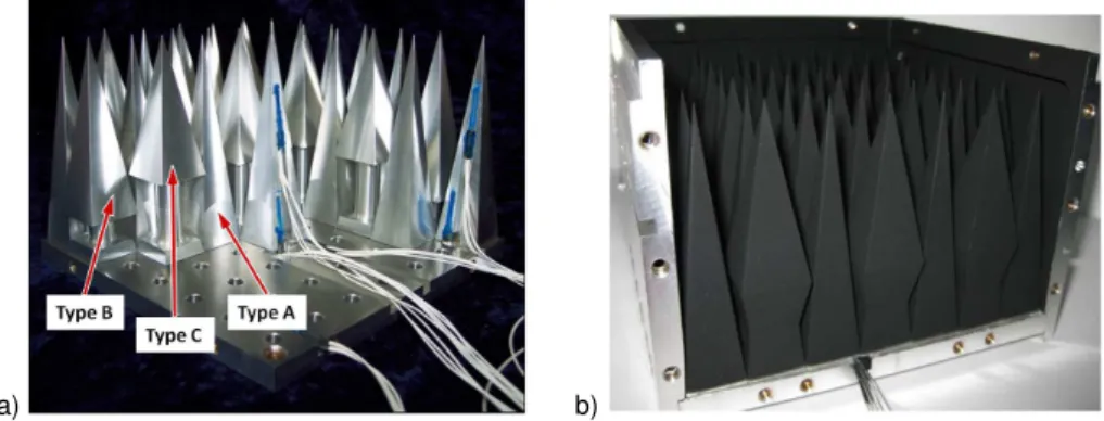
Fig. 4.Design of the optical surface: array of 49 individual pyramids(a)varnished with NEXTEL-Velvet Coating(b).
3.1 Mechanical design and emissivity of a GLORIA BlackBody (GBB)
Strict design requirements had to be applied in order to meet the scientific goals. Besides the highest precision of the opti-cal surfaces with maximal emissivity (>0.997), weight and space limitations had to be considered as well. Since GLO-RIA uses a large two-dimensional detector array for infrared limb observations, large-area blackbody radiation sources for radiometric calibration are necessary. Due to the FOV of the FTS the aperture of a GBB needs a minimum size of 102 mm×102 mm with an inhomogeneity in radiance tem-perature across the optical surface of less than 0.15 K. Fig-ure 3 illustrates the design of a GLORIA BlackBody (GBB). In order to meet the specification of the required emis-sivity, the optical surface of a GBB with the dimension of 126 mm×126 mm consists of an array with 49 individual pyramids made of aluminium. Since surfaces perpendicular to the line-of-sight should be avoided as direct reflections di-minish the emissivity of a blackbody, the pyramids have dif-ferent square bases on difdif-ferent levels (see Fig. 4). The base of type A is 18 mm×18 mm whereas type B and type C have a slightly bigger base (20 mm×20 mm).
The NEXTEL-Velvet Coating 811-21 that is used as sur-face finish for the pyramids as well as for the inner walls of the casing has a measured emissivity of greater than 0.967 in the spectral range from 5 to 12 µm (e.g. Lohrengel and Todtenhaupt, 1996). Due to the steep angles of the pyramid apexes (83–79◦) most of the incoming radiation, which is not absorbed, is reflected into the back, and thus the effec-tive emissivity is enhanced. Since the bases of type B and type C pyramids are elevated (see Fig. 4), light traps are formed which prevent direct back reflection. The NEXTEL surface coating has a nearly Lambertian radiation character-istic. Geometry factors for the pyramid array in a medium-size box (L= 182 mm) have been calculated for the radiative exchange between each area element of the pyramids and the aperture according to Howell (2010) (see Eq. 2). Weighted with the surface finish emissivity of 0.967, the calculations yield an effective emissivity of 0.9996. The measureduǫ of the coating is about 1 % leading to an effectiveuǫof 0.0003.
F1−2=
1 π·A2
ln
A21+B2
+22
(Y2+2)·(X2+2)
+ Y2+41/2
Ytan−1 Y
(Y2+4)1/2−Xtan−1(Y2+X4)1/2
+ X2+41/2
Xtan−1 X
(X2+4)1/2−Ytan−1(X2+4X)1/2
a) b)
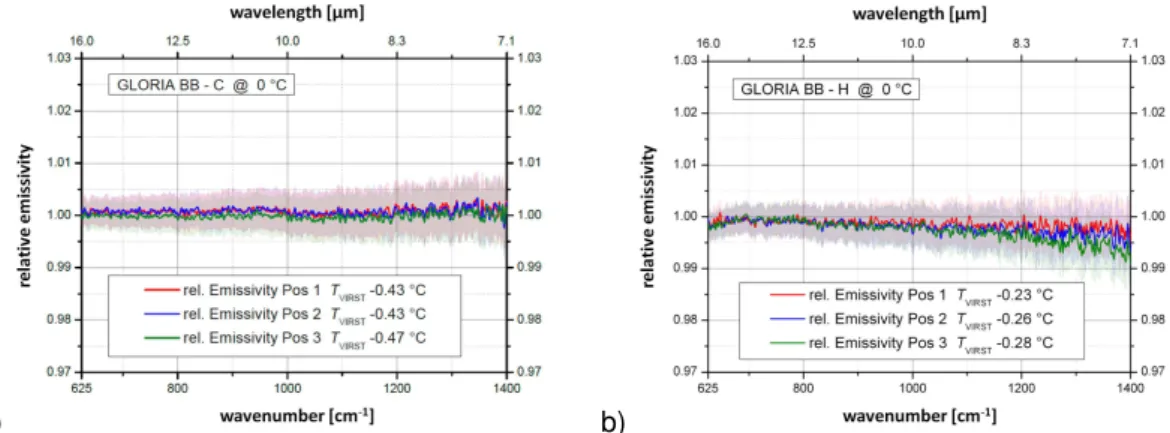
Fig. 5.Relative spectral emissivity of GBB-C(a)and GBB-H(b). The shaded areas represent the uncertainty of each measurement (two sigma).
witha= 126 mm (pyramid array width), b= 102 mm (aper-ture width), c= 182 mm (box length), A=a/c, B=b/a,
X=A·(1+B),Y=A·(1−B).
Measurements at PTB, the national metrology institute of Germany, confirm the results of the emissivity calculation. The measurements were performed at a temperature of 0◦C. Figure 5 shows the relative spectral emissivity in the spectral range from 7 to 16 µm of both blackbody calibration sources measured at three positions on the pyramid array (pyramid type A, B, C marked as 1, 2, 3 in Fig. 6). The shaded ar-eas in the panels represent the two sigma confidence inter-val. With respect to the uncertainties of these measurements neither significant deviations from 1 are visible nor are lo-cal effects apparent for both blackbody lo-calibration sources, which corroborates the assumption about the emissivity and verifies the absence of spectral features.
The optical surface of a GBB is temperature-controlled by a system consisting of an assembly of four two-stage Thermo-Electric Coolers (TECs). Details of the thermal de-sign are given in Sect. 3.2. In Fig. 6 the positions of the TECs on the back side of the optical surface are marked in green. The temperature of the optical surface is measured at specific pyramids using platinum resistance thermometers (PRTs). Locations and positions of the ten PRTs are illus-trated in Figs. 4 and 6. The labelled red circles correspond to the individual temperature sensors.
The aluminium casing which surrounds the optical sur-face is partly thermally decoupled, while the front part serves as a stray light baffle which is also temperature-controlled by TECs (see Fig. 3a). The stray light baffle is operated at a slightly lower temperature in order to act as a wa-ter vapour trap to inhibit condensation on the black opti-cal surface. The in-flight blackbody opti-calibration sources are suspended by GFRP (Glass-Fibre-Reinforced-Plastic) tubes for thermal decoupling. In order to reduce the adverse in-fluence of the thermal environment, the GBBs are covered with a 50 mm insulation made of extruded polystyrene foam (XPS) sheets. The outermost layer of the cover is composed
Fig. 6.Array configuration: the little red circles show the locations of the PRTs, the greenish areas indicate the positions of the TECs on the backside of the array, the white circles represent the FOV of the corner pixels of the detector array. The numbered orange spots mark the areas of the spectral measurements.
of aluminium foils for EMC (Electro-Magnetic Compatibil-ity) reasons. The overall weight of one GBB is 9.5 kg.
3.2 Thermal design
a) b)
c) d)
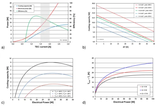
Fig. 7.TEC 128A0020 performance:(a)calculation forTc=−50◦C andTh=−30◦C as a function of TEC current,(b)cooling capacity at various ambient temperatures,(c)cooling capacity at various temperature differences betweenThandTcwithTc=−50◦C and(d)maximum achievable1T as a function of electrical power for different external heat loadsQ.
by using XPS sheets for thermal protection. Those relatively small heat loads can easily be handled by standard TECs.
Unfortunately, cool-down of the GBBs cannot start before aircraft take-off due to the risk of water vapour contamina-tion. For this reason, the GLORIA in-flight calibration sys-tem is more or less at ambient sys-temperature before take-off of the aircraft. Since it is highly desirable to be operational in the UTLS region as early in the flight as possible, the time constants for reaching the operating temperatures of the blackbodies had to be optimised.
3.2.1 Physical properties and performance of selected TECs
Since TECs show highly nonlinear temperature dependence particularly with regard to their thermoelectric power, ther-mal conductivity, and internal resistance, it is important to carefully select the right type for the envisaged deployment. In addition, available voltages and power consumption must also be considered, since the power available for the black-body calibration system is very limited. For temperature sta-bilisation of the GBB optical surface, the TEC type Peltron 128A0020 was selected and for the stray light baffle tem-perature control the TEC type Peltron 128A2427, respec-tively. Characteristics of the TECs for an ambient temper-ature (Tamb) of−30◦C are given in Table 2 including the one used for the GBB prototype (Peltron 128A2013).
Cooling capacity, power consumption and efficiency as a function of various parameters like TEC current and am-bient temperature have been calculated for TEC 128A0020
and for TEC 128A2427, respectively. The results for TEC 128A0020 are shown in Fig. 7. For a cold side temper-ature (Tc) of −50◦C and a hot side temperature (Th) of −30◦C, cooling capacity, power consumption and efficiency as a function of TEC current are given in Fig. 7a. The shaded area (TEC current between 1.5 and 2 A) indicates the range for optimum performance. Figure 7b illustrates TEC perfor-mance for various ambient temperatures. The cooling capac-ity is plotted as a function of1T, the temperature difference betweenThandTcof the TEC. In case of optimal heat dissi-pation on the hot side,Thshould be close toTamb. Thus,1T is almost equal to the difference betweenTambandTc. The cooling capacity as a function of electrical power for vari-ous temperature differences betweenTc andThis shown in Fig. 7c. The high dependency of the TEC performance onTh is obvious. Therefore, every effort was made to keep the tem-perature of the hot side as low as possible. The maximum1T
as a function of electrical power has been calculated for dif-ferent external heat loadsQ(see Fig. 7d). The results clearly show that the dependence of the maximum achievable1T
on the electrical power is highly nonlinear. That means in practice that a power increase above a certain value is not reasonable because it will not significantly lowerTc.
a) b)
Fig. 8.Model simulation for the thermal behaviour during ascent:(a)the GBB prototype with a constant electrical current of 3 A and (b)optimal cooling of GBB-C optical surface during a Geophysica ascent (calculated forITEC= 1.5 A).
Table 2.Physical properties of selected TECs at−30◦C.
Type Size Thermoelectric Thermal Internal power conductivity resistance [mm×mm] [V K−1] [W K−1] []
128A0020 40×40 0.042 0.28 2.8
128A2427 62×62 0.042 0.89 0.94
128A2013∗ 50×50 0.042 1.21 1.28
∗Used for the prototype.
3.2.2 Heat load management
Since the effectiveness of TECs and thus the achievable low-est temperature is primarily determined by the temperature of the hot side of the TECs, passive and active elements for heat dissipation were designed with great effort. Massive ra-diators combined with cooling fans work as heat sinks. The efficiency of the heat sink is highly dependent on the air pres-sure and the ambient temperature which in turn is determined by the flight level of the aircraft and the heat load inside the instrument compartment.
Considering the power limitation and the weight margin, a radiator with 0.6 K W−1and a cooling fan with an airflow of 252 m3h−1 were selected for each thermal control unit. The radiators are directly positioned on top of the TECs to avoid additional thermal resistance. They are mechanically fixed to the thermal control plate on the opposite side of the TECs using low heat conducting material. This sandwich structure also holds the TECs in place.
3.2.3 Thermal performance during ascent
It is a primary goal that the blackbody calibration system is ready for service as soon as possible after take-off. The most time consuming operation is to reduce the temperatures from about+20◦C on the ground to−30◦C inside the in-strument compartment of the aircraft at flight level. Those times depend on the heat capacity of the aluminium struc-ture as well as the cooling efficiency. The cooling efficiency on the other hand is contingent on the available electrical
power and the performance characteristics of the TECs. The thermal behaviour of the GBB prototype during ascent sim-ulation with a constant electrical current of 3 A is shown in Fig. 8a with1T referring to the initial temperature. Compre-hensive model simulations yield a heat load of 25 W for the achieved temperature difference of 47 K. Cooling down the GBB-C optical surface withITEC= 1.5 A result in an optimal performance. The results of the simulation shown in Fig. 8b are based on a simulated Geophysica flight reaching an alti-tude of 19 km.
3.3 Accuracy of calibration measurements
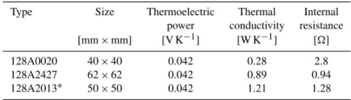
Based on the final design of the GBBs, uncertainty calcu-lations for various operating temperatures of GBB-C and GBB-H were performed. Environmental conditions were confined to the parameters used in Sect. 2.2. Figure 9 illus-trates howugainanduoffdepend on the operational temper-atures of GBB-C and GBB-H. It is apparent that even with GBB-C at a temperature as high as 240 K and GBB-H just 30 K above, the total gain uncertainty is about 0.5 %. Op-erating GBB-C at a temperature of 230 K and GBB-H at 270 K will result in a total gain uncertainty of less than 0.4 %. This configuration leads to a maximum offset uncertainty of about 25 nW (cm−2sr cm−1)−1. Detailed calculations show that the temperature uncertainty uT is the dominant factor for the total accuracy. The uncertainty of the emissivity is about one order of magnitude smaller.
3.4 Instrumentation and GBB electronics
a) b)
Fig. 9.Radiance uncertainty as a function of GBB-C and GBB-H temperatures:(a)total gain uncertainty and(b)maximum offset uncertainty.
Fig. 10.Schematic of the GBB-electronics: power supply, temperature measurement module, control unit and the efficient power stage for controlling the TECs and the cooling fans.
a low uncertainty in the determination of the calibration pa-rameters, it is more important to measure precisely the actual temperature and the temperature distribution on the black op-tical surface than to finely adjust a certain value.
The GBB electronics, developed and built at the Institute for Data Processing and Electronics (IPE) of KIT, also pro-vides the power for all electrical components and is housed in a separate box located above the GBBs (see Fig. 3b).
The technical requirements for the GBB electronics in-clude low weight, low power consumption and low heat gen-eration implying low power dissipation. To fulfil the calibra-tion requirements, extremely precise temperature measure-ments are supplied. The GBB electronics also controls the TECs and the cooling fans and delivers all GBB data to the GLORIA data acquisition system. The GBB electronics it-self consists of four modules (see Fig. 10): the temperature measurement module for 48 PRTs, an efficient power stage for controlling 12 TECs and 4 cooling fans, a communica-tion and control unit (Xilinx Virtex-4 FX12 Mini-Module) and a power supply for all internal electric voltages.
Since the TECs and the cooling fans are operated at 15 V, the maximum available current for the TECs is only 2.3 A, re-sulting in a maximum electrical power for cooling the optical
surfaces of 138 W. Heat dissipation from the TEC power stage and from the power supply was carefully designed using high heat conducting materials and an effective low-weight radiator attached to the GBB electronics box.
In addition the GBB electronics components are selected for airworthiness, to endure low temperature and low pres-sure, and for effective heat dissipation on ground and dur-ing flight. They are designed to withstand extreme environ-ments from the tropics to the tropopause. Safety shut-down in case of overheat, circuit malfunction or electrical short is included. The GBB electronics successfully passed all vi-brational, electro-magnetic compatibility and environmental tests proving to be suitable for deployment on an airborne platform.
4 GLORIA BlackBody performance
a) b)
c) d)
Fig. 11.Simulated thermal behaviour of GBB optical surfaces in two different scenarios. Upper panel: Scenario No. 1 (cold instrument com-partment) for(a)GBB-C and(b)for GBB-H. Lower panel: Scenario No. 2 (warm instrument compartment) for(c)GBB-C for(d)GBB-H.
components of a GBB were parameterized as related to their thermal characteristics. The thermal model is a very useful tool to create ideally suited configurations for the in-flight calibration. The thermal behaviour of the optical surface and of the stray light baffle were calculated separately. For se-lected conditions the calculated values were verified by envi-ronmental tests performed in the thermal vacuum test cham-ber of the Research Centre Juelich. The estimated heat loads for the optical surface (GBB-OS) and for the stray light baf-fle, respectively, are given in Table 3.
Removing the permanent external heat load on a GBB is not the most difficult task. The internal energy stored in the aluminium mass of one pyramid array (m= 3.8 kg) making up for a temperature difference of 50 K, equals 171 kJ. For the baffle (m= 1.8 kg) it equals 81 kJ, respectively. In order to cool the optical surface of one GBB from+20◦C to−30◦C an average cooling power of about 50 W is needed to reach the desired temperature in less than one hour.
4.1 Cooling rates and power consumption
The most critical part in the thermal management is the heat dissipation on the hot side of the TECs. The performance and thus the achievable minimum temperature are highly de-pendent on the ability to transfer the produced heat to the ambient air. Natural convection as well as forced convection are unfortunately reduced due to the low pressure at flight level (p <200 hPa). Table 4 gives temperatures and cooling rates for the GBB optical surface at several points in time
Table 3.Estimated heat loads for the GBB.
(a) Heat load portions
Element Thermal Radiation Convection @
conduction p= 200 (80) hPa
[mW K−1] [mW K−4] [mW K−1]
GBB-OS 65 8×10⁻¹¹ –
GBB-Baffle 60 2.5×10⁻¹⁰ 75
(b) Heat loads for various scenarios (GBB-C)
Tamb Th Tc p GBB-OS GBB-Baffle Total
heat load heat load heat load [◦C] [◦C] [◦C] [hPa] [W] [W] [W]
−10 −10 −20 200 0.7 1.6 2.3 −50 −50 −60 200 0.7 1.5 2.2 −50 −50 −60 80 0.7 1.3 2.0
as a function of the electrical current, taking into account changes in ambient temperature and pressure during take-off and flight.
As clearly seen from Table 4, an increase in power from 72 W (1.5 A) to 130 W (2 A) does not improve the cooling rate. In consequence, the most relevant factor for the cooling rate is the heat capacity of the aluminium structure.
0.5 7.3 295 287 −0.5 278 −0.6 261 −0.6
0.75 17 295 285 −0.7 274 −0.7 256 −0.6
1 31 295 283 −0.8 271 −0.8 251 −0.7
1.25 50 295 282 −0.8 269 −0.9 249 −0.7
1.5 72 295 281 −0.9 268 −0.9 248 −0.7
2 130 295 281 −0.9 268 −0.9 249 −0.6
a) b)
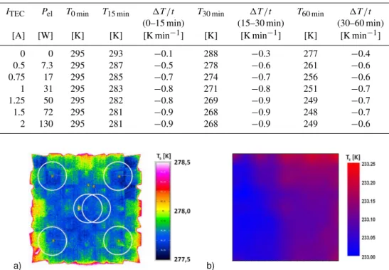
Fig. 12.Radiance temperature distribution of the black optical surface:(a)infrared image of the 2008 prototype taken by a thermographic camera in the lab (ambientT andp) with the white circles representing the FOV of individual GLORIA detector pixels.(b)GBB-H flight model radiance temperature measured by VIRST at the RBCF of PTB (TGBB= 233 K). Depicted is the smoothed distribution of radiance temperature resulting from a measured grid of 11 by 11 points.
with an electrical current of 1.4 A. In scenario No. 2 a flight with ambient temperature dropping to −18◦C and a final pressure level of 80 hPa is simulated which corresponds to a flight in a hot Geophysica instrument compartment. In this scenario the TECs of the optical surface are operated with an electrical current of 2 A, which is equal to 130 W of electrical power. The thermal behaviour of GBB-H was also simulated for the same scenarios. Results are shown in Fig. 11b and d. Scenario No. 1 compares to scenario No. 1 of the GBB-C simulation. In this scenario the TECs of the optical surface are operated with an electrical current of 0.9 A. In scenario No. 2 which compares to scenario No. 2 of GBB-C, all TECs are switched off and cooling occurs passively only.
4.2 Spatial homogeneity of optical surface radiance temperature
As required for optimal performance, the temperature gradi-ent on the black optical surface as seen by the individual de-tector pixels should be less than 150 mK. From the infrared image of the 2008 prototype optical surface at a mean tem-perature of about 278 K taken by a thermographic camera in the lab at ambient pressure (Fig. 12a), a maximum tem-perature gradient of 80 mK between different FOVs of indi-vidual detector pixels could be derived. As the convection
process inside the blackbody is not reduced in the lab envi-ronment and the absolute temperature is higher than under flight conditions, these findings only give an indication for the expected spatial inhomogeneity in radiance temperature during in-flight calibration at flight level.
In Fig. 12b the GBB-H radiance temperature measured by the Vacuum InfraRed Standard radiation Thermometer (VIRST) at the Reduced Background Calibration Facility (RBCF) of PTB is shown with the pyramid array at 233 K, while the pressure inside of the RBCF was set to 100 hPa. Depicted is the smoothed distribution of radiance temper-ature resulting from a measured grid of 11 by 11 points. Compared to the prototype, spatial temperature homogeneity could be improved, although there is still a residual temper-ature gradient due to the fact that the individual tempertemper-ature control of the four sectors did not work perfectly.
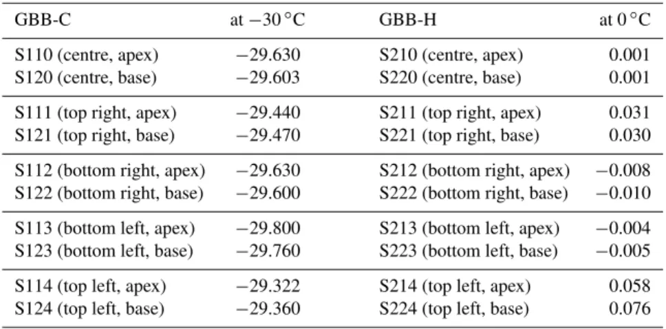
Table 5.Radiance temperature measurements of the GBB optical surface at −30◦C for GBB-C and at 0◦C for GBB-H, respectively. Measurement positions are given in Fig. 6.
GBB-C at−30◦C GBB-H at 0◦C
S110 (centre, apex) −29.630 S210 (centre, apex) 0.001 S120 (centre, base) −29.603 S220 (centre, base) 0.001
S111 (top right, apex) −29.440 S211 (top right, apex) 0.031 S121 (top right, base) −29.470 S221 (top right, base) 0.030
S112 (bottom right, apex) −29.630 S212 (bottom right, apex) −0.008 S122 (bottom right, base) −29.600 S222 (bottom right, base) −0.010
S113 (bottom left, apex) −29.800 S213 (bottom left, apex) −0.004 S123 (bottom left, base) −29.760 S223 (bottom left, base) −0.005
S114 (top left, apex) −29.322 S214 (top left, apex) 0.058 S124 (top left, base) −29.360 S224 (top left, base) 0.076
temperatures of the GBBs are listed in Table 5. The tem-perature gradient between the pyramid apex and its base is less than 40 mK for GBB-C at−40◦C and less than 20 mK for GBB-H at 0◦C indicating the good homogeneity within one pyramid. Also the overall spatial homogeneity in radi-ance temperature at 0◦C was already better than the desired 150 mK, whereas at−30◦C deviations of about 400 mK are visible. This deviation should be easily accounted for by reg-ulating the various TECs with respect to the PRTs, what had not been done for these specific measurements. In this case only a single temperature setting was provided for the ther-mal control plate of the optical surface. Improvements are expected when (a) the TEC control electronics is optimised and (b) the temperature setting can be higher resolved.
4.3 Thermal vacuum test chamber results
To assure optimal performance of the GLORIA in-flight blackbody calibration system on board an aircraft, it is im-portant to know the specific thermal properties in order to get the most direct control over its behaviour during the mission. In order to simulate realistic flight conditions, environmen-tal tests were performed in the thermal vacuum test chamber of Research Centre Juelich. One goal was to minimise time for cool-down, so operational readiness is accomplished as soon as possible. Unfortunately cool-down cannot begin be-fore aircraft take-off due to the risk of water vapour contam-ination or even ice formation.
The thermal characteristics of the GBBs during the var-ious phases of a flight were investigated in order to ensure all components will withstand the environmental conditions at flight level, to validate the thermal model, and to acquire a solid data base for the development of an in-flight opera-tional concept.
In order to measure the influence of convection, the GBBs were operated with open and closed apertures. No significant differences were detected either in the cooling rates or the
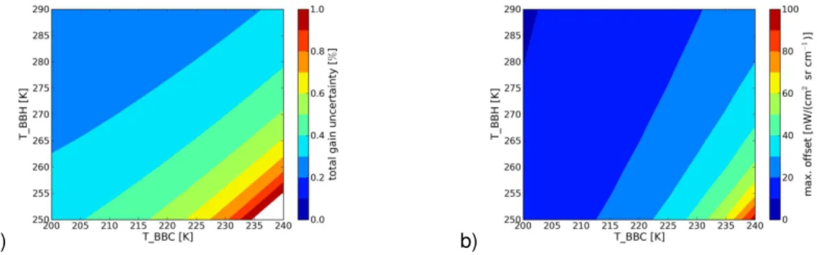
required power in the calibration mode. Figure 13a shows the thermal behaviour of the GBB-C optical surface during a simulated ascent assuming that the final ambient temper-ature in the aircraft bay will be−33◦C. The TECs of the optical surface were operated with 1.3 A which corresponds to an electrical power of less than 50 W. After one hour the optical surface of GBB-C reached a temperature of−20◦C while the stray light baffle cooled down to−40◦C manifest-ing that due to the lower mass the coolmanifest-ing of the baffle is not a time-critical procedure.
Although GBB-H was operated with lower power (<25 W), GBB-H optical surface reached a temperature of −16◦C after 60 min which is just 4 K above the GBB-C tem-perature. As shown in Fig. 13b, the temperature of the radi-ator (Trad) is significantly lower due to the lower dissipat-ing excess heat. Compardissipat-ing the test results with the thermal model (see Fig. 11) excellent agreement is found.
Tests under various extreme conditions were also per-formed. In one of the tests the two GBBs were operated in very different modes: GBB-C was powered with the maxi-mal possible power of up to 120 W whereas GBB-H was just cooled passively. Results are shown in Fig. 13c and d. After one hour the optical surface of GBB-C reached a tempera-ture of−18.5◦C while the stray light baffle cooled down to −33◦C. Trad is significantly higher (+17◦C) compared to the test shown in Fig. 13a, and b due to the higher dissipat-ing excess heat. A massive influence of the ambient pressure is also clearly seen in Fig. 13c. When the ambient pressure drops from 200 to 80 hPa,Tradincreases from 9 to 20◦C. The passive cooling of GBB-H results in a temperature of−4◦C after 60 min. Again, comparing the results for the tested ex-treme conditions with the thermal model (see Fig. 11c and d) excellent agreement is reached.
a) b)
c) d)
Fig. 13.Thermal behaviour during ascent simulation test. Upper panel: Scenario No. 1 (cold instrument compartment, finalTamb=−33◦C) of(a)GBB-C optical surface with TEC power<50 W and(b)GBB-H optical surface with TEC power<25 W. Lower panel: Scenario No. 2 (warm instrument compartment, finalTamb=−18◦C) of(c)GBB-C optical surface with TEC power<120 W and(d)GBB-H optical surface with TEC power = 0 W.
25 min of the flight) in various scenarios, values from 0.7 to 1.1 K min−1were measured, whereas for the stray light baf-fle an almost constant linear gradient of about 1.8 K min−1 is found. Operating the TECs of GBB-C without the cool-ing fans will not lead to a stable temperature of the optical surface within the calibration temperature range.
After having reached the desired temperature level, tem-perature stabilisation is required. Since less power is needed to keep the temperature constant, Trad drops, leading to a smaller temperature difference betweenTh andTc of the TECs and thus even less power over time is required un-til equilibrium is reached. Table 6 gives the electrical power necessary to keep a constant and homogeneous temperature field for calibration.
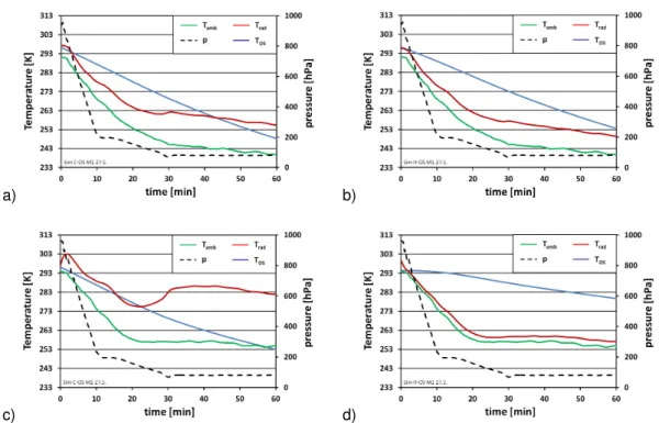
Figure 14 shows the results for the first part of a simulated HALO flight. An ascent to 10 km in 10 min and a further rise to a final pressure level of 150 hPa was simulated, while the temperature inside the instrument compartment dropped to 223 K. After about 45 min GBB-H reached its target temper-ature of 255 K and was stabilised. It took about two hours for GBB-C to reach 218 K, which was 5 K below ambient tem-perature. The minimum temperature was reached after about three hours when the GBB electronics stabilises GBB-C as
well. Details are given in Fig. 14b. Again, the temperature in sector No. 4 could not be controlled perfectly.
5 ITS-90 traceability
To achieve the required low uncertainty of less than 100 mK in the optical surface radiance temperature of the GBBs, a calibration of the used contact thermometers and perform-ing corrections for non-ideal emissivity, possible thermal gradients and temperature inhomogeneities is not sufficient. In fact, only a direct comparison of the surface radiance temperature and the spectral radiance of the GBBs with the blackbody radiation coming from high-quality cavity radi-ators linked to the primary national standards of radiance temperature yields sufficiently small uncertainties and strict traceability to the International Temperature Scale (ITS-90). Furthermore, the systematic long-term investigation of the radiometric performance of the GLORIA in-flight blackbody calibration system at the highest possible metrological stan-dard will enable further development and improvement of the blackbody calibration sources, also for future applications on board of balloons and satellites.
Table 6.Power required for GBB optical surface temperature stabilisation.
Ambient Ambient Optical surface 1T Electrical Total power Total power temperature pressure temperature current for cooling for GBB-C
[◦C] [hPa] [◦C] [K] [A] [W] [W]
(a) GBB-C
−45 80 −54 9 0.25 8.5 26.5
−46 80 −59 13 0.45 12 30
−46 80 −64 18 0.60 16 34
(b) GBB-H
−25 80 0 25 0.7 11 18
−48 230 0 48 0.9 27 34
−48 230 −21 27 0.8 14 21
a) b)
Fig. 14.GBB-HALO flight simulation test:(a)GBB-C temperature (T-sensor S110) and GBB-H temperature (T-sensor S210) during the first three hours of the flight,(b)thermal behaviour of GBB-C optical surface after two flight hours.
calibrated in the Reduced Background Calibration Facility (RBCF) of PTB (Monte et al., 2009a, b). The RBCF allows the calibration of spectral radiance and radiance temperature under environmental conditions similar to those during flight operation. The calibration is performed by direct comparison of the blackbody calibration sources with reference cavity blackbody radiators (emissivity>0.9997) of known radiance temperature. The radiance temperatures of the GBB optical surfaces were determined in the range from−50 to 0◦C with an uncertainty of less than 100 mK (two sigma).
For the measurement of spectral radiance this comparison is performed via a Fourier Transform Spectrometer, for the radiance temperature via the broadband radiance thermome-ter VIRST (8 to 14 µm) as transfer instruments (Gutschwager et al., 2008). With a transfer radiation thermometer the ra-diance temperature of the reference cavity blackbody radia-tors of the RBCF is directly linked to the heat-pipe black-bodies of PTB (?)hollandt03, the primary national SI stan-dards of radiance temperature in Germany. The radiance tem-perature of the heat-pipe blackbodies has been compared to the radiance temperature scale of other national metrol-ogy institute in international comparisons to assure their
worldwide consistency at the highest metrological standard (Gutschwager et al., 2013).
6 Summary and conclusions
quired emissivity, the optical surface of a GBB consists of an array with 49 individual pyramids of three different shapes. The chosen geometry ensures multiple reflection of all in-coming radiation for the whole surface except the pyramid tips. The NEXTEL-Velvet Coating used as surface finish for the pyramids as well as for the inner walls of the casing has a nearly Lambertian radiation characteristic and a mea-sured emissivity of greater than 0.967. The aluminium cas-ing which surrounds the optical surface is partly thermally decoupled, while the front part serves as a stray light baffle. The stray light baffle is operated at a slightly lower tempera-ture in order to act as a water vapour trap to inhibit conden-sation on the black optical surface. The calculated effective emissivity of the black pyramid array in a medium-size box is 0.9996, which is well above the requirement.
For temperature control of the black optical surface, Thermo-Electric Coolers (TECs) are used offering the advan-tage of avoiding cryogens and mechanical coolers. An addi-tional benefit of TECs is the dual utilisation for cooling and heating by just switching the direction of the electrical cur-rent. The selected TECs are precisely tailored to the limited available electrical power and are capable of providing the re-quired temperatures. An assembly of four two-stage Peltron 128A0020 is used to generate a stable and homogeneous ra-diance temperature field across the black optical surface of each GBB. For the temperature control of the stray light baf-fle two single-stage TEC type Peltron 128A2427 are applied. The temperature is measured by PT100 resistance thermome-ters which are directly calibrated to the radiance tempeture emitted from the optical surface versus the national ra-diance calibration standard. Strict traceability to the Interna-tional Temperature Scale (ITS-90) has been attained by var-ious measurements at PTB, the German national metrology institute. The achieved spatial temperature homogeneity of ±0.075 K, which fully complies with the requirements, can further be improved by modifying the software of the GBB electronics, which has been developed and implemented at IPE of KIT. The temperature measurements yield a noise of ±0.025 K while the temperature drift was found to be less than 25 mK in 30 min. The overall performance of the GLO-RIA blackbody calibration sources is far beyond the required uncertainty of less than 100 mK.
The GLORIA in-flight calibration system was extensively tested in numerous thermal vacuum tests proving that it can be operated very well in the hostile environment of the UTLS region with mutable low temperature and pressure. The com-prehensive thermal model is a useful tool to further increase the efficiency of the thermal control system. It has been
the pyramid array may further improve the homogeneity of the radiance temperature field across the black optical sur-face. In order to reduce the time before the GLORIA in-flight blackbody calibration system is operational at flight level, either more electrical power must be made available or, in a new approach, the design of the optical surface is to be changed for weight optimisation, so that thermal mass is fur-ther reduced. Recurring measurements at PTB, the German national metrology institute, will ensure a continuous qual-ity and complete traceabilqual-ity to the International Temperature Scale (ITS-90).
Acknowledgement. Part of this work has been supported by the European Metrology Research Programme (EMRP) within the joint research project Metrology for Earth Observation and Climate (MetEOC). The EMRP is jointly funded by the EMRP participating countries within EURAMET and the EU.
Edited by: C. von Savigny
References
ESA: Candidate Earth Explorer Core Missions – Report for Assess-ment: PREMIER – PRocess Exploitation through Measurements of Infrared and millimetre-wave Emitted Radiation, vol. SP-1313/5, ESA Publications Division, ESTEC, Noordwijk, the Netherlands, 2008.
ESA: Report for mission selection: PREMIER, vol. SP-1324/3, ESA Publications Division, ESTEC, Noordwijk, the Nether-lands, 2012.
Friedl-Vallon, F., Riese, M., Maucher, G., Lengel, A., Hase, F., Preusse, P., and Spang, R.: Instrument concept and preliminary performance analysis of GLORIA, Adv. Space Res., 37, 2287– 2291, doi:10.1016/j.asr.2005.07.075, 2006.
Friedl-Vallon, F., Gulde, T., Hase, F., Kleinert, A., Kulessa, T., Maucher, G., Neubert, T., Olschewski, F., Piesch, C., Preusse, P., Rongen, H., Sartorius, C., Schneider, H., Schönfeld, A., Tan, V., Bayer, N., Blank, J., Dapp, R., Ebersoldt, A., Fischer, H., Guggenmoser, T., Höpfner, M., Kaufmann, M., Kretschmer E., Nordmeyer, H., Oelhaf, H., Orphal, J., Riese, M., Schardt, G., Schillings, J., Sha, M. K., Suminska-Ebersoldt, O., and Unger-mann, J.: Instrument concept of the imaging Fourier transform spectrometer GLORIA, Atmos. Meas. Tech., in preparation, 2014.
Gutschwager, B., Hollandt, J., Jankowski, T., and Gaertner, R.: A vacuum infrared standard radiation thermometer at the PTB, Int. J. Thermophys., 29, 330–340, doi:10.1007/s10765-007-0349-x, 2008.
Gutschwager, B., Theocharous, E., Monte, C., Adibekyan, A., Reiniger, M., Fox, N. P., and Hollandt, J.: Comparison of the radiation temperature scales of the PTB and the NPL in the tem-perature range from−57◦C to 50◦C, Meas. Sci. Technol., 24, 065002, doi:10.1088/0957-0233/24/6/065002, 2013.
Hollandt, J., Friedrich, R., Gutschwager, B., Taubert, D., and Hart-mann, J.: High-accuracy radiation thermometry at the National Metrology Institute of Germany – the PTB, High Temp.-High Press., 35/36, 379–415, 2003/2004.
Howell, J. R.: A catalog of radiation heat transfer configuration ftors, available at: http://www.engr.uky.edu/rtl/Catalog/(last ac-cess: 20 March 2013), 2010.
ISO/IEC: Guide 98-3:2008 Uncertainty of measurement – Part 3: Guide to the expression of uncertainty in measurement, JCGM – Joint Committee for Guides in Metrology, Genf, 2008.
Lohrengel, J. and Todtenhaupt, R.: Waermeleitfaehigkeit, Gesamte-missionsgrade und spektrale EGesamte-missionsgrade der Beschichtung Nextel-Velvet-Coating 811-21 (RAL90015 tiefschwarz matt), PTB-Mitt., 106, 259–265, 1996.
Monte, C., Gutschwager, B., and Hollandt, J.: The reduced background calibration facility for detectors and radiators at the Physikalisch-Technische Bundesanstalt, in: Proc. of SPIE, Vol. 7474, Sensors, Systems, and Next-Generation Satel-lites XIII, 747414, edited by: Meynart, R., Neeck, S. P., and Shi-moda, H., Berlin, Germany, doi:10.1117/12.830454, 2009a. Monte, C., Gutschwager, B., Morozova, S., and Hollandt, J.:
Radia-tion thermometry and emissivity measurements under vacuum at the PTB, Int. J. Thermophys., 30, 203–219, doi:10.1007/s10765-008-0442-9, 2009b.
Olschewski, F., Rolf, C., Steffens, P., Kleinert, A., Piesch, C., Ebersoldt, A., Monte, C., Gutschwager, B., Hollandt, J., Preusse, P., Friedl-Vallon, F., and Koppmann, R.: In-flight black-body calibration sources for the GLORIA interferometer, in: Proc. SPIE 8511, Infrared Remote Sensing and Instrumenta-tion XX, Marija Strojnik; Gonzalo Paez, San Diego, California, USA, 85110I, doi:10.1117/12.928194, 2012.
Ploeger, F., Fueglistaler, S., Grooß, J.-U., Günther, G., Konopka, P., Liu, Y. S., Müller, R., Ravegnani, F., Schiller, C., Ulanovski, A., and Riese, M.: Insight from ozone and water vapour on transport in the tropical tropopause layer (TTL), Atmos. Chem. Phys., 11, 407–419, doi:10.5194/acp-11-407-2011, 2011.
Preusse, P., Schroeder, S., Hoffmann, L., Ern, M., Friedl-Vallon, F., Ungermann, J., Oelhaf, H., Fischer, H., and Riese, M.: New perspectives on gravity wave remote sensing by space-borne infrared limb imaging, Atmos. Meas. Tech., 2, 299–311, doi:10.5194/amt-2-299-2009, 2009.
Riese, M., Friedl-Vallon, F., Spang, R., Preusse, P., Schiller, C., Hoffmann, L., Konopka, P., Oelhaf, H., von Clarmann, T., and Höpfner, M.: GLObal limb Radiance Imager for the Atmosphere (GLORIA): scientific objectives, Adv. Space Res., 36, 989–995, doi:10.1016/j.asr.2005.04.115, 2005.
Riese, M., Ploeger, F., Rap, A., Vogel, B., Konopka, P., Dameris, M., and Forster, P.: Impact of uncertainties in atmospheric mixing on simulated UTLS composition and related radiative effects, J. Geophys. Res., 117, D16305, doi:10.1029/2012JD017751, 2012. Riese, M., Preusse, P., Oelhaf, H., Friedl-Vallon, F., Hoepfner, M., Hoor, P., Kaufmann, M., Orphal, J., Ploeger, F., Spang, R., Ungermann, J., Vogel, B., and Woiwode, W.: The Gimballed Limb Observer for Radiance Imaging of the Atmosphere (GLO-RIA): Scientific Objectives, Atmos. Meas. Tech., in preparation, 2014.
Solomon, S., Qin, D., Manning, M., Chen, Z., Marquis, M., Av-eryt, K. B., Tignor, M., and Miller, H. L. (Eds.): Technical Sum-mary in Climate Change 2007: the Physical Science Basis, Con-tributions of Working Group I to the Fourth Assessment Re-port of the Intergovernmental Panel on Climate Change, Cam-bridge University Press, CamCam-bridge, UK and New York, NY, USA, 2007.
Solomon, S., Rosenlof, K. H., Portmann, R. W., Daniel, J. S., Davis, S. M., Sanford, T. J., and Plattner, G.-K.: Con-tributions of stratospheric water vapor to decadal changes in the rate of global warming, Science, 327, 1219–1223, doi:10.1126/science.1182488, 2010.
Stevenson, D. S., Dentener, F. J., Schultz, M. G., Ellingsen, K., van Noije, T. P. C., Wild, O., Zeng, G., Amann, M., Ather-ton, C. S., Bell, N., Bergmann, D. J., Bey, I., Butler, T., Co-fala, J., Collins, W. J., Derwent, R. G., Doherty, R. M., Drevet, J., Eskes, H. J., Fiore, A. M., Gauss, M., Hauglustaine, D. A., Horowitz, L. W., Isaksen, I. S. A., Krol, M. C., Lamarque, J.-F., Lawrence, M. G., Montanaro, V., Pitari, G., Prather, M. J., Pyle, J. A., Rast, S., Rodriguez, J. M., Sanderson, M. G., Sav-age, N. H., Shindell, D. T., Strahan, S. E., Sudo, K., and Szopa, S.: Multimodel ensemble simulations of present-day and near-future tropospheric ozone, J. Geophys. Res., 111, 148–227, doi:10.1029/2005JD006338, 2006.