Mestrado em Engenharia e Gestão Industrial
Process Optimization in the Core Manufacturing
Department of a Foundry Industry
Relatório de estágio
apresentado para a obtenção do grau de Mestre em
Engenharia e Gestão Industrial
Autor
Eduardo Miguel Silva Lourenço
Orientador
Dr. José Manuel Torres Farinha
Instituto Superior de Engenharia de Coimbra
Supervisor
Eng. Luís André Xavier Pinto de Azevedo
Fucoli – Somepal Fundição de Ferro, SA
ii
“One, remember to look up at the stars and not down at your feet. Two, never give up work. Work gives you meaning and purpose and life is empty without it. Three, if you are lucky enough to find love, remember it is there and don't throw it away.”
iii
AGRADECIMENTOS / ACKNOWLEDGMENTS
A realização do presente trabalho não teria sido possível sem a orientação, o apoio e incentivo de diversas pessoas, a quem quero deixar expresso o meu sincero agradecimento.
Primeiramente, agradeço ao Professor Doutor José Manuel Torres Farinha, pelos ensinamentos, pelo apoio, pelos conselhos e pela minuciosa correção desta dissertação.
À Administração da Fucoli-Somepal, SA por ser a empresa promotora da oportunidade de formação e pela oportunidade de realizar o projeto nas suas instalações.
Ao Eng.º Luís Xavier demonstro o meu reconhecimento pelo tempo despendido e por me ter recebido no seu ambiente de trabalho.
Ao Eng.º Pedro Quaresma, Eng.º Marcelo Abrantes e Eng.º Vítor Pires pela integração, compreensão, preocupação e partilha de conhecimento durante o desenvolvimento deste projeto.
Ao Manuel, Bruno, Henrique, Daniel, João e Adriana pela amizade e por me terem acompanhado durante este ano de mestrado.
Aos meus amigos mais próximos que me acompanham desde sempre e que nunca deixaram de estar presentes para mim.
A Gina e ao Zé pelo apoio e carinho prestado durante esta fase da minha vida e a toda a minha família pelo apoio incondicional.
A minha namorada, Filipa, pelo apoio incondicional ao longo deste ano, mas também ao longo da nossa aventura, o meu sincero obrigado por me fazer acreditar e também por nunca deixar de acreditar em mim.
Aos meus pais, a peça mais importante, os que tornaram isto tudo possível e por terem sido um grande apoio, não há palavras que possam expressar o meu agradecimento.
O meu obrigado a todas as outras pessoas que participaram direta ou indiretamente nesta fase da minha vida.
iv
RESUMO
A atual globalização, assim como o aumento da competitividade nos mercados nacionais e internacionais, deu origem a um ambiente imprevisível que levou as organizações procurar soluções para se superarem e procurar melhorar, de forma continua os seus processos produtivos nos ramos em que se encontram inseridas, com o objetivo de prestar um serviço superior e disponibilizar produtos com qualidade elevada e com menos custos associados. A implementação de metodologias relacionadas com a filosofia Lean tem revelado aumento na competitividade das organizações através de processos de melhoria contínua, para a redução de desperdícios assim como a otimização e normalização de processos e organização dos espaços de trabalho. Este novo paradigma de produção levou a muitas empresas adotar esta filosofia, no entanto a sua implementação nem sempre é bem sucedida. Neste trabalho são identificadas e caracterizadas alguns paradigmas e ferramentas desta filosofia, assim como algumas causas das falhas na implementação.
Esta dissertação surge no âmbito de um estágio numa empresa líder nacional no setor da fundição, com o objetivo de otimizar os processos produtivos no departamento da Macharia através de uma abordagem SMED para redução dos tempos de troca de caixas de machos e TPM para aumentar a produtividade dos equipamentos e colaboradores do mesmo departamento.
v
ABSTRACT
The current globalization, as well as the increase in competitiveness in national and international markets, originated an unpredictable environment that led organizations to seek solutions to overcome and continuously improve their production processes in the sectors in which they are inserted, with the objective of providing superior service and high quality products with less associated costs.
The implementation of methodologies related to Lean philosophy has revealed an increase in competitiveness of organizations through continuous improvement processes, for the reduction of waste as well as the optimization and normalization of processes and organization of workspaces. This new paradigm of production has led many companies to adopt this philosophy, however its implementation is not always successful. In this work some paradigms and tools of this philosophy are identified and characterized, as well as some causes for implementation failure.
This dissertation arises as part of an internship in a leading national company placed in the foundry sector, with the objective of optimizing the production processes in the core manufacturing department through a SMED approach in order to reduce the setup times in the interchange of core boxes and TPM to increase productivity in the equipment and employees of the same department.
vi
LIST OF CONTENTS
AGRADECIMENTOS / ACKNOWLEDGMENTS ... iii
RESUMO ... iii
ABSTRACT ... v
LIST OF FIGURES ... viii
LIST OF TABLES ... x
LIST OF ACRONIMS ... xi
1. INTRODUCTION ... 12
1.1 Foundry Industry ... 12
1.1.1 Brief History ... 12
1.1.2 Estimation of the current situation in world’s casting production ... 13
1.2 Fucoli - Somepal, Fundição de Ferro, SA ... 14
1.2.1 Organization and Products... 17
1.2.2 Markets ... 20
1.2.3 Productive Process ... 22
1.3Paperwork Goals ... 24
1.4 Work Structure ... 24
2. STATE OF THE ART ... 26
2.1 Lean Manufacturing ... 26
2.1.1 Brief History of Lean Manufacturing ... 26
2.1.2 General Concepts, Principles and Waste ... 29
2.1.3 Lean Implementation Challenges in SME’s ... 33
2.1.4 Lean Manufacturing Tools ... 35
2.2 Single Minute Exchange of Die (SMED) ... 36
2.2.1 Origin and Historical Background ... 36
2.2.2 Method Description ... 37
2.3 TPM - Origin and Historical Background ... 39
2.3.1 Method Description ... 39
3. EXPERIMENTAL WORK ... 43
3.1 Introduction ... 43
3.2 SMED – Bicor 3300 ... 43
3.2.1 Brief Description of the Process ... 43
3.2.2 Diagnosis and set of Benchmark Times ... 45
vii
3.3 Autonomous Maintenance Plan ... 56
3.4 Standardization of Procedures ... 62
3.5 Other improvements performed ... 63
3.5.1 Elimination of the covers from the core boxes ... 63
3.5.2 Creation of a wharf for the logistics train ... 65
4. DISCUSSION ... 66
5. CONCLUSIONS AND PROPOSALS FOR FUTURE WORK ... 73
5.1 Concluding Remarks ... 73
5.2 Future Perspectives ... 74
viii
LIST OF FIGURES
Figure 1.1 – Ancient Casting Process………..8
Figure 1.2 – Leading countries share in world casting industry………...18
Figure 1.3 – Main markets served by foundry industry………...19
Figure 1.4 – Key moments of Fucoli–Somepal………...21
Figure 1.5 – Organizational Structure of both facilities...23
Figure 1.6 – Categories of cast irons………...24
Figure 1.7 – Microstructure of nodular cast iron………....24
Figure 1.8 – Categories of products produced in Fucoli-Somepal, SA………...25
Figure 1.9 – Markets………...26
Figure 2.1 – Taiichi Ohno, the mentor of TPS ………..…...32
Figure 2.2 – TPS Temple………...33
Figure 2.3 – Continuous Process Improvement………...36
Figure 2.4 – SMED Implementation Stages………...43
Figure 2.5 – Relationship between the 6 sources of loss and OEE……….46
Figure 2.6 – House of TPM………47
Figure 3.1 – Placement of a sand core in the foundry department………...48
Figure 3.2 – Placed sand cores before iron pouring………....49
Figure 3.3 – BICOR 3300………...50
Figure 3.4 – Cavities that should be covered………...…...53
Figure 3.5 – Conveyors used to transport core boxes……….54
Figure 3.6 – Existing sequence platform ………...54
Figure 3.7 – 3D representation of the graduated tool………..55
Figure 3.8 – Electromagnetic system ………...56
Figure 3.9 – Misplaced fixation studs………57
Figure 3.10 – State of the work station………...58
ix
Figure 3.12 – Unorganized accessories ………...59
Figure 3.13 – Unorganized accessories………..59
Figure 3.14 – Mixer ready to be disassembled………...62
Figure 3.15 – Cleaning of the propeller………...63
Figure 3.16 – Final result………...63
Figure 3.17 – Covers of the mixer before and after intervention………..64
Figure 3.18 – Sand blasting unit ………...64
Figure 3.19 – Gassing unit………...65
Figure 3.20 – Inside layout of the equipment……….65
Figure 3.21 – Remaining residues after cleaning………...66
Figure 3.22 – Products of core box number 259……….67
Figure 3.23 – Faulty filling of the core box………68
Figure 3.24 – Wharf created in the carpentry ………69
Figure 4.1 – Action Plan………70
Figure 4.2 – Barcodes generated for each component………...74
Figure 4.3 – Chart of OEE fluctuation during April 2018………..75
x
LIST OF TABLES
Table 1.1 – Countries affiliated with Fucoli – Somepal……….26
Table 2.1 – Comparison between Toyota and Ford's production system………33
Table 2.2 – Five fundamental lean principles……….35
Table 3.1 – Times Measured………..51
xi
LIST OF ACRONIMS
FIFO GM HRM IMVP JIPE JIPM JIT LM MDF MIT MTS NVA OEE SME SMED TPM TQC TQM TPS TMC USA VSMFirst In First Out General Motors
Human Resources Management International Motor Vehicle Program Japan Institute of Plant Engineers Japan Institute of Plant Maintenance Just In Time
Lean Manufacturing
Medium Density Fibreboard
Massachusetts Institute of Technology Make To Stock
Non Value Added
Overall Equipment Efficiency Small and Medium Enterprises Single Minute Exchange of Die Total Productive Maintenance Total Quality Control
Total Quality Management Toyota Production System Toyota Motor Company Unites States of America Value Stream Mapping
1.INTRODUCTION
12
1. INTRODUCTION
1.1 Foundry Industry
Casting production has been one of the main influencers for the development of world’s economy. According to Holtzer and co-workers, the progress achieved over the last few years in foundry engineering has shown a path to further developments of foundry technology. The last decade brought significant changes in the world map for the greatest casting producers (Holtzer, Danko and Zmankowska-Kumon, 2012). Sand casting is the process used to shape molten ferrous metals and non-ferrous alloys, where molten material its drawn by gravity into the mould and then left to cool and solidify. Thompson stated that, because sand casting relies on gravity to draw the molten material into the mould cavity, there will always be an element of porosity in the cast part (Thompson, 2007). To eliminate the roughness of the cast process, products often have to be finished using abrasive materials or machining. The moulds and cores are usually made from sand that is bonded with clay or synthetic materials and pressed into the pretended cavity or shape. Some of the steps involved in the casting process are pattern and core making, moulding, melting and pouring the metal, finishing, cleaning and testing.
The casting process has shown its versatility by achieving complex metal shapes with great durability and a reduced amount of labour involved. Therefore, the resultant products can be found in numerous applications, the automotive industry alone is responsible for half of the world’s production, followed by industrial engineering, construction and infrastructures systems, electronics, medical and aviation products. Metal casting foundries became significant consumers of scrap metal transforming obsolete and worn objects into useful new products.
1.1.1 Brief History
Since ancient times foundry has been a part of the human history. Modern civilization would not be as advanced if it was not for the discovery and development of foundry industry and its products. The history of foundry is traced back to the ancient period in which metallic objects in the form of coins, arrows, and household articles were made through melting the metal followed by pouring it into suitable moulds. The foundry history is mainly related to the
1.INTRODUCTION
13
craftsmen of Greek and Roman civilizations and since then, the role of casting metals acquired unique significance.
Figure 1.1 – Ancient Casting Process
1.1.2 Estimation of the current situation in world’s casting production
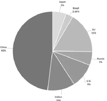
The casting production is one of the main factors that impact the development of world´s economy. It is shown that casting production has suffered a substantial growth in the past decade. Despite this, the total production of casting in 2010 (91.4 million tons) was in fact lower than the production of 2008 (93.5 million tons), the highest peak was in 2007, when casting production equalled to 94.9 million tons (Holtzer, Danko and Zmankowska-Kumon, 2012). The world leader in the casting production for many years was China, which produced 43% of the castings in 2010 as it is shown in Figure 1.2. The EU countries share in the casting production corresponds to approximately 15 %. India presents a smaller production, with a share of 10%.
1.INTRODUCTION
14
The European foundry industry is the third largest in the world in the casting of ferrous metals and the second largest for non-ferrous metals. France, Italy and Germany are the countries with the highest production in Europe, each one with a total annual production of over two million tons of castings. The highest fraction of casting production is constituted by grey iron castings, with approximately 48% of the total. Castings of spheroidal cast iron represent nearly 25% and the segment of steel casts corresponds to approximately 11%. The non-ferrous metals castings are dominated by aluminium alloy casting, with approximately 11% of the total world casting production. The percentage of magnesium, zinc, copper is very small (Holtzer, Danko and Zmankowska-Kumon, 2012).
Figure 1.3 shows the most significant markets that foundry industry serves. Automotive industry, mostly in the field of motorization is the biggest market server by this industry, with a share of 50%. Engineering industry is the second sector with most use of casting manufactured products with 30%, general engineering and construction sectors have the lowest share in this market (J.Danko and M.Holtzer, 2006).
1.2 Fucoli - Somepal, Fundição de Ferro, SA
Fucoli – Somepal Fundição de Ferro, SA it’s a Portuguese group with two units located in Coimbra and Pampilhosa dedicated to the production and commercialization of cast iron products for the water and sanitation segment. With several decades of experience in the development and manufacture of its products, Fucoli – Somepal has reached a solid position in
Figure 1.3 – Main markets served by foundry industry. Adapted from: Holtzer, Danko and Zmankowska-Kumon, 2012
1.INTRODUCTION
15
the market where good service to its customers, the quality of the products and the compliance of delivery dates are embedded in the company’s policy.
The company was created in 1946 with the birth of Fucoli – Fundição Conimbricense, Lda in Coimbra, but only in 1949 started the manufacturing of products for the water and sanitation sector. Some years later, in 1957 Somepal – Sociedade Metalúrgica da Pampilhosa, Lda is founded to manufacture several types of valves. In 1990 Fucoli, Lda acquires the share capital of Somepal, Lda, and performs relevant investments and modifications in order to secure the quality-price ratio.
The manufacturing line is modernized and a quality system is implemented. The NP EN ISO 9002 was granted in 1994 for the Mealhada unit and, in 1996, to the Coimbra unit. It was not until 1998 that the merge between Fucoli – Fundição Conimbricense, Lda and Somepal – Sociedade Metalúrgica da Pampilhosa, Lda took place providing a larger production scale for both clients and suppliers. The company then adopted the designation Fucoli – Somepal Fundição de Ferro, SA. Since the date of the merge, several investments were made regarding equipment and the facilities, thus modernizing the production process. In 2005 the cupola furnace was replaced by an electric unit providing more efficiency and less environmental impact.
The Pampilhosa unit has been progressively increasing its covered area and modernizing the equipment associated with the process of finishing parts, with the purchase of a painting robot and installation of new CNC devices. In 2009 Fucoli – Somepal, SA acknowledged, in its Coimbra unit, the certification of its environmental management system. Since 2011, the company has implemented Lean manufacturing methodologies in the production and organizational processes to ensure high quality standards and a fast response to its client’s needs. In 2017, a runner smasher equipment was acquired to improve the melting process time, and two smart storage systems were installed to store the core boxes and the grinding tools for the finishing processes. Figure 1.4 shows some of the key moments of the Fucoli – Somepal Group.
1.INTRODUCTION
16
1.INTRODUCTION
17
Among the two production units the company employs around 200 people and the annual production is around 15000 tons, about 50% is dedicated to exportation. The products are manufactured with high quality standards and homologation for several international entities such as CERTIF in Portugal, AENOR in Spain, KIWA in The Netherlands and RINA in Italy. CE Marking is applied to products when required by legislation. Fucoli – Somepal also holds the NP EN ISO 9001 certification in both units and NP EN ISO 14001 certification in the head office.
1.2.1 Organization and Products
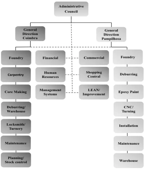
Fucoli – Somepal, SA. has two industrial facilities located in Coimbra, and Mealhada (in the civil parish of Pampilhosa). The company is internally divided in departments that work together with the purpose of obtaining the best final product. There are different sectors among the headquarters facilities and the branch office; hence some stages of the productive process can only be completed in one of the production units. Figure 1.5 shows the organization of both production units.
Although, both facilities hold the equipment to accomplish most of the productive processes to reach the final products on its own, the production system is distributed between the two facilities. The headquarters is responsible for the entire production of cores used in the foundry process in both facilities, the manufacturing of most of the foundry products, grinding and painting the most demanded and smaller size products. It is also where all the moulds are created, maintained and stored. The branch office is mainly responsible for grinding and refurbishment processes using CNC equipment, the manufacture of larger foundry pieces plus all the products that have a consumption of less than 20 units per year, the design and production of some core boxes, assembly and testing products plus the epoxy paint process.
1.INTRODUCTION
18
Figure 1.5 – Organizational Structure of both facilities
Fucoli-Somepal´s products are manufactured in a material known as nodular cast iron. Cast iron belongs to the family of ferrous alloys with a large variety of proprieties. It can be casted in the desired shape instead of being worked in the solid state. Unlike steels, that normally contain less than 1% of carbon contents, cast iron generally possess 2% to 4% of carbon and 1% to 3% of silicon. Other nodular elements might be present, allowing to control or modify certain proprieties.
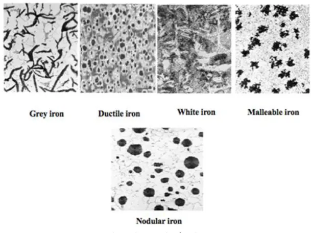
Cast iron can be distinguished in four types or different categories, according to the distribution of the carbon in the microstructure, as shown in Figure 1.6: grey, ductile, white and malleable. Ductile or nodular cast irons also known as cast iron with nodular or spheroidal graphite, are the ones that Fucoli-Somepal is currently manufacturing.
1.INTRODUCTION
19
Figure 1.6 – Categories of cast irons
Ductile cast iron presents a good fluidity, good leakage suitability, excellent machining ability and decent resistance to wear. Additionally, ductile cast iron has similar proprieties to steels, like high mechanical resistance, tenacity, ductility, hot deformability and temperability. Due to the presence of graphite spherical nodules in the inter structure, these irons have exceptional engineering properties, as seen in Figure 1.7. The existence of a relatively ductile matrix between the nodules tolerates significant deformation without the occurrence of fracturation.
1.INTRODUCTION
20
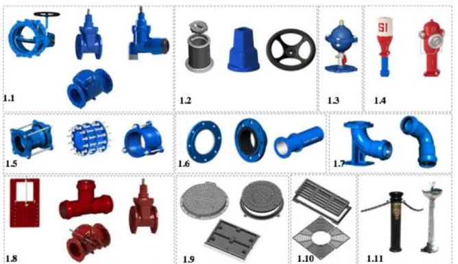
The non-bonded ductile cast iron contains a content of carbon that fluctuates between 3% to 4%, and the content of silicon fluctuates between 1.8% and 2.8%. Other impurities should be kept at low levels, since they are able to interfere with the formation of graphite nodules in the ductile cast iron. At this time, the activities developed by the company are focused in the production of materials associated to water and sanitation, gas and telecommunications sectors. The range of products manufactured at Fucoli-Somepal, SA are shown in Figure 1.8.
Figure 1.8 – Categories of products produced in Fucoli-Somepal, SA: 1.1 - Valves (soft sealing gate valves, Service Connection Soft Sealing Gate Valves, check valves, other valves; 1.2 - Valve accessories; 1.3 - Air valves; 1.4 - Fire Hydrants; 1.5 - saddles and joints; 1.6 - Flanges and pipes; 1.7 - Ductile iron fittings; 1.8 - Valves and fittings for residual use; 1.9 - Manhole covers;
1.10 - Gully great; 1.11 - Sight furnishings
The products manufactured at Fucoli-Somepal are nearly 100% recyclable and there is no prediction of ambient impacts associated with its use during the entire life time.
1.2.2 Markets
Half of the products manufactured and commercialized by Fucoli – Somepal go to internal markets, where the main customers are city councils, municipal services, civil construction companies, warehouses, public works and other industries. The remaining 50% percent are exported to external markets, as shown in Figure 1.9 and Table 1.1, to several countries, in four continents, such as Europe, Africa, America and Asia.
1.INTRODUCTION
21 Figure 1.9 – Markets
Table 1.1 – Countries affiliated with Fucoli – Somepal
Europe Africa America Asia
Germany Belgium Croatia Denmark Spain Finland France Greece Netherlands Ireland Italy Lithuania Luxemburg Moldavia Poland UK Romania Russia Czech Republic Serbia Sweden Switzerland Ukraine Angola Algeria Burkina Faso Burundi Cape Verde Chad Ivory Coast Egypt Guinea-Bissau Libya Mali Morocco Mozambique Niger Nigeria Kenya
Central African Republic Democratic Republic of Congo
Senegal Tanzania Tunisia Uganda Argentina Bolivia Brazil Canada Chile Cuba Ecuador Jamaica Uruguay Venezuela Afghanistan Saudi Arabia Azerbaijan Kazakhstan United Arab Emirates
Iraq Israel Jordan Kuwait Macao Oman Qatar Sri Lanka Vietnam Lemm
1.INTRODUCTION
22
1.2.3 Productive Process
Carpentry:
The productive process of Fucoli – Somepal begins in the carpentry. It is the department where moulds are designed, prepared and some of the core boxes are manufactured.In terms of geometry, the mould is similar to the cast iron piece intended to be produced. The mould is 1% larger than the cast iron piece because of the contraction suffered during solidification. Moulds can be produced in resin, wood or aluminium. Aluminium moulds are used when regarding high demand products in order to prevent wear in the mould and also when the goal is to achieve a superior superficial finish of the cast product. The mould plates are numerically identified and stored in racks, as well as the negatives and core boxes.
Core Manufacturing:
The production of the core boxes is related to the production of the necessary elements to create hollow products. Among the headquarters and the branch office, the company has five equipment that allow the production of cores in different sizes. The process used to achieve the production of cores is known as the cold box method, where sand is mixed with resins that act as binders, pressurized into the core boxes and then hardened with a catalyser that accelerates the resin reaction. After the mixture of sand and binders is pressurized into the core boxes, hardening of the core is achieved by gassing the curing agent, into the core boxes at room temperature. Subsequently, dry air is conducted through the core box to perform a washing step, therefore allowing the demoulding of the core.
After the cores are extracted, the next procedures are final touches, where burrs are trimmed to correct any defects and painted is applied, when necessary. The painting operation allows an improvement in the superficial finish of the casted product.
Foundry:
The moulding process used is known as green moulding, and the main components are: sand of appropriate grain size and shape;
binders in the form of clay, namely bentonite; additives, such as coal dust;
1.INTRODUCTION
23
In the headquarters, the components mentioned above are stored in silos and then routed to a mixer. This process is entirely autonomous, the added quantities of each element are monitored and defined through a computer controlled system. The prepared sands are then fed to the forming machine. In this equipment sand is weighted regarding the product that is being manufactured at the moment.
Each moulding box is obtained while putting together two half mouldings boxes, the mould plate will be sequentially pressed into the bottom and top half’s. Sequentially, the half mouldings move to the station where placement of the cores occurs. The half-moulds are then overlapped following to the metal pouring section. In the headquarters, the raw materials are stored in pits ant then extracted using electromagnets that are linked to a weighing system.
The operator weights materials, according to the defined instructions, and a procedure is monitored for the addition of each component. The casting returns are the runnersand all the defective parts that are not able to be re-worked. At the headquarters there are two half ton furnaces that have the ability to produce four tons per hour, while one of them contains the melted iron ready to be poured; the other one is in the process of melting, allowing flow of the operations without stoppage times due to the iron not being ready to pour. The liquid metal is then inserted into an automatic casting system and poured into the moulds. In the branch office the pouring is performed manually. After casting, the moulds are transported to the crushing area during a period of approximately one and a half hours, which allows the cooling to room temperature. In the crushing zone the non-used pieces are removed from the moulding boxes trough vibration, plus the sand is collected and re-routed for later reuse.
Shot blasting:
After crushing, the remaining pieces are introduced in baskets and then transported to the blasting machine. In this device, the casting pieces are hit with small metal spheres that remove excess sand from previous procedures.
Grinding:
After the parts are clean, the burrs are removed using different equipment, depending on the type of product and the necessary finish, such as:
automatic Grinding Machines; angle grinders.
1.INTRODUCTION
24
In the headquarters, the pieces that are painted black are sent to the immersion painting system. The rest is sent to the storage area for later shipment to the branch office.
Machining:
The machining process is understood as the one that provides the desired shape, size and finish. This sector is equipped with CNC machines to guarantee great quality and
reliability of the final products.
Epoxy painting:
At this stage the painting of the pieces is carried out, mostly in blue. This consists on the application of a layer of uniform paint on the whole exposed part of the piece in order to prevent corrosion formation during the whole life cycle of the product.
Assembly and testing:
In this department the technical specifications of the respective products are available and all parts are assembled and submitted to hydraulic tests, in order to check their strength and tightness.
1.3 Paperwork Goals
This work was developed in the scope of the Master’s Degree in Industrial Management Engineering, to describe the various functions integrated throughout the internship. The dominant goal was process optimization in order to reduce setup times of the core manufacturing boxes and improve overall efficiency of the core manufacturing department. It was also attempted the implementation of an autonomous maintenance plan in the core manufacturing equipment, considered the bottleneck of the operation and standardization of procedures to increase productivity among employees related to the same equipment.
1.4 Work Structure
Regarding the structure of this work, it is divided into five chapters. In the first chapter a perspective on foundry industry is created, followed by the presentation of the company where the work was performed, emphasizing the type of products manufactured, the productive process and the markets that its inserted. This chapter is closed with the aim of this work and its structure. The second chapter includes the literary revision of the fundamental topics for the accomplishment of this work, such as Lean Manufacturing, some of its tools and the difficulties that Small and Medium Enterprises (SME) face when implementing these techniques. SMED and TPM are mentioned as the main tools used during this project at Fucoli – Somepal, SA. In
1.INTRODUCTION
25
the third chapter the experimental work and the knowledge acquired in the core manufacturing department during the internship is stated. The discussion of the work accomplished is defined in the fourth chapter. Finally, the fifth chapter regards the conclusions of the presented work and proposes future projects.
2.STATE OF THE ART
26
2. STATE OF THE ART
2.1 Lean Manufacturing
During the 21st century, industries all around the world are constantly struggling with their shareholders in order to increase the productivity at their production units. In a reality where competitiveness is huge, not only between organizations in the same field of business, but also between manufacturing units in the same group, the producers keep looking for possibilities to increase the efficiency of their production processes therefore its competitiveness (Carvalho, 2006). The intensification of globalization means that is necessary to evaluate the markets in a global perspective, where SME’s compare themselves with organizations worldwide and, also, world class performance becomes the goal for those manufacturing organizations (Soltan and Mostafa, 2015). As markets keep shifting, meeting the challenges of worldwide competition between manufacturers requires a bundle of practices. Such goals can be achieved through diverse methods, such as the purchase of new technology, enhancement of services, quality improvements and waste reduction (Pech e Vaněček, 2018). Therefore, Lean Manufacturing (LM) is a common practice among organizations in order to achieve the desired performance for its production units. In 2014, Mahmood stated that Lean represents more than its tools, that it is a philosophy and its implementation is a long term approach where organizations need to, continuously, place efforts in order to achieve significant improvements (Mahmood, 2014).
2.1.1 Brief History of Lean Manufacturing
Lean manufacturing methodologies are related to the automotive industry since its early stage: the first vehicles were produced with low efficiency and excessive costs meaning that they were not available for the average citizen (Makhomu, 2012). Henry Ford was aiming to expand the availability of the car to a wider range of consumers, something that would only be possible through the reduction of the production costs hence reducing the price of sale price. Ford recognised these limitations and changed the industry’s standards through the development of numerous techniques that currently would be associated with Lean manufacturing. These techniques led to the introduction of the moving assembly line, which, according to Womack and Jones, is the basic premise for what nowadays we call a continuous flow production system (Womack, J.P. and Jones, D.T. 2003).
Ford Motor Company was growing gradually and, in Japan, the autonomous mechanical loom was introduced by Sakichi Toyoda in 1918. Toyoda Automatic Loom Works was later established, in 1926. Following the creation of Toyoda’s company, his son Kiichiro, travelled to the United States of America (USA) where he had the opportunity to connect with the
2.STATE OF THE ART
27
automotive industry and gained great interest due to the innovative character that it represented. The proceeds from the sale of the patent related to the loom allowed the creation of a vehicle department at the current company and, in 1937, Toyota Motor Company (TMC) is established, in a market entirely dominated by Ford and General Motors (GM) (Holweg, 2007). Due to the short volume of sales after the second World War, Kiichiro was replaced by Eiji Toyoda, its cousin, and, in 1950, Eiji travelled to the USA to study the western production methods in order to implement them in the family’s company. The solution offered by Toyota led to the complete renovation of the company and gave birth to the introduction of an alt ernat ive production system. In result of the western journey, and having Taiichi Ohno as its mentor (Figure 2.1) the Toyota Production System (TPS) was introduced.
Figure 2.1 – Taiichi Ohno, the mentor of TPS
Ford and GM’s production systems were based in mass production, relying on economies of scale and large equipment to produce the largest amount of parts as affordable as they possibly could. Meanwhile the Japanese market, after the second World War was small; therefore, Toyota was forced to create several type of vehicles in smaller quantities with the same manufacturing process to satisfy its consumer’s needs (Simões, 2008).
The main differences between the American and Japanese production systems are presented in Table 2.1. By highlighting Just-in-Time (JIT) production and Total Quality Control (TQC), lead times were reduced and the production lines were kept flexible. The TPS was adopted by many Japanese manufacturers, which provided them a distinct competitive advantage, related to western ones (Simões, 2008). According to Cusumano, in the late 80’s, the output per worker was two to three times higher than in the US or European plants (Cusumano, 1994).
2.STATE OF THE ART
28
Table 2.1 – Comparison between Toyota and Ford's production system
As mentioned above, Lean production is related to the TPS, and the general idea behind the TPS is to produce the kind of units needed, at the time needed in quantities such, that unnecessary intermediate and finished product inventories can be eliminated. According to Pettersen, the basis of the TPS is the absolute elimination of waste and the two pillars that support the TPS are JIT and Jidoka or autonomation (Pettersen, 2009). The bundle of tools and principles associated with the TPS methodology are represented through the TPS temple, in Figure 2.2.
2.STATE OF THE ART
29
JIT expresses that nothing should be produced, transported or bought before the need appears, therefore avoiding waste. Jidoka states that during the occurrence of anomalies, the production could possibly be interrupted in an autonomous way, assuring the quality of the entire process. The fundamental objective of the TPS is represented in the top of the temple, i.e., to achieve an growth in productivity and efficiency by avoiding waste, as in an industrial environment, waste may represent about 60% of the total value chain (Hines, P., Taylor, D. 2000).
The term “Lean” was introduced by Krafcik, in 1988; at that time, the leading researcher in the International Motor Vehicle Program (IMVP) at the Massachusetts Institute of Technology (MIT). Since it was pioneered by Toyota, Lean production has evolved and has been widely adopted by many organizations around the world in numerous forms and several designations. Today, it still is one of the most promoted and competitive management models in use. The current interest in Lean represents the industrial and service organizations validation of its applicability, as Lean methods are, nowadays, also applied in hospitals, insurance companies and financial services, plus can be beneficial in order to improve productivity in services with an appropriate approach in which customer satisfaction must be considered.
Although, the trend of Lean implementation continues; it is a reality that its success rate is low, namely because of the numerous obstacles faced by the organizations, that are challenging to overcome. Unfortunately, there is no recipe that can assure a successful implementation. Also, unsuccessful implementation can take a great impact on the organization’s resources and affect employees and their confidence in Lean philosophy (Almanei, Salonitis and Xu, 2017).
2.1.2 General Concepts, Principles and Waste
Lean Production or Lean Manufacturing, is a long-term organizational culture that focuses on eliminating waste with the goal of increasing productivity by doing more with less resources, that is, more quality that best serves the demand of customers with less human effort, time, materials and space (Austin, 2013). Krafcik in 1988 mentioned Lean as a manufacturing approach that compared to mass production uses less of everything: half the human effort in the factory, half the manufacturing space, half the investment in tools, and half the engineering hours to develop a new product in half the time. Also it requires keeping far less than half the needed inventory, resulting in fewer defects, and producing a greater variety of products (Krafcik, 1988).
LM achieved a major expansion since Womack and its co-workers released the work “The Machine That Changed the World”, in 1990, based on the TPS, JIT and all its core
2.STATE OF THE ART
30
characteristics (Olhager and Prajogo, 2012). LM is a methodology that involves the simultaneous use of several techniques and tools. Four bundles of related and consistent practices are used, JIT, Total Quality Management (TQM), Total Productive Maintenance (TPM) and Human Resources Management (HRM) (Shah and Ward, 2003). The Lean task is to have the shortest lead time possible, optimum level of strategic inventory, higher customer service levels, higher quality and lowest waste throughout the entire supply chain, in order to win the marketplace (Juran and De Feo, 2010).
According to Womack and Jones, Lean thinking is transversal and suited to be applied, not only in industries, but also in services, construction, projects, consulting, among others (Womack and Jones, 2003). Therefore, there are five fundamental principles to define Lean methodology, as the Table 2.2 shows.
Table 2.2 – Five fundamental lean principles 1. Identify value from
customer point of view
Meaning that companies need to identify and initiate product design and manufacture by focusing on the needs of their customers.
2. Value Stream Mapping (VSM)
The principle of VSM is to identify all the steps in the value stream for each product family, eliminating every step, action and practice that does not create value. Value is added to a product when the work is done on the piece; non-value adding steps are represented when the product is waiting in batches or stocks, which is considered waste.
3. Create Flow
This principle describes that is imperative to transfer the product through one value adding step to the next one and keep the production in a constant flow. Organizations must avoid batches and queues or, at least, continuously reduce them and not once interrupt a value adding step by a non-value adding step.
4. Establish Pull
Pull means meeting consumer’s rate of demand with production without reaching overproduction. Most organizations will have to push a certain point and response to a final costumer from that point. The idea is to push this point as long upstream in the manufacturing process as possible, waiting for the demand and then create the product as fast as possible and with high quality as possible.
5. Seek Perfection
As value is specified, value streams are identified, wasted steps are removed, flow and pull are introduced; then, the process starts a new cycle and continues until a state of perfection is reached, in which perfect value is created with zero waste.
2.STATE OF THE ART
31
Professionals who think Lean, are always aiming for perfection and, performing the improvement cycle is a never ending process, leading to continuous improvements that cover all the aspects at the improvement level, as shown in Figure 2.3.
Figure 2.3 – Continuous Process Improvement
Although, Lean does not produce immediate results; the full benefits come only when it becomes the basis for a process of continuous improvement able to keep the results over time. For many companies, namely the process industries, this culture transformation is the hardest change they must reach. However, for assured sustainability the organizations that are truly Lean, will invest the time and efforts to support a change in their culture.
Across this document, we determined that the main goal of Lean implementation is the reduction of waste. According to Soltan and Mostafa, waste elimination refers to eliminate Non-Value Added (NVA) activities from the supply chain and that NVA’s depend on the activities performed by the organization (Soltan and Mostafa, 2015). In fact, due to the lack of space and natural resources, Japanese developed repulsion to waste. Therefore, Lean is a philosophy dedicated on identifying and eliminating waste throughout a product’s entire value stream, extending, not only within the organisation, but also along the entire supply chain (Schroeder, 2008). In the book titled “The Toyota Way”, Liker demonstrated that waste can be categorized into eight different types:
1) Overproduction
o Manufacturing products or providing services, for which there are no orders, leading to unnecessary storage, staffing and transport costs (Liker, 2004);
2. Map the Value Stream 3. Create Flow 4. Establish Pull 5. Seek Perfection 1.Identify Value
2.STATE OF THE ART
32 2) Waiting
o Having people stand inactive for long periods and waiting, for different reasons, like the next processing step, equipment downtime or refiling stocks (Liker, 2004);
3) Unnecessary Transportation
o This type of waste relates to all type of transportation that is pointless. Examples of this could be transporting work in progress through long distances or moving materials into or out of storage between processes (Liker, 2004);
4) Over Processing
o Processes can be inefficient due to taking unnecessary steps in order to produce a piece or by having a poor product design. Also providing a higher quality than necessary will create waste (Liker, 2004);
5) Excess Inventory
o Normal effects of having excess inventory include longer lead-times, higher transport and storage costs. Another problem with inventories is that they tend to hide problems such as production imbalances, equipment downtime and long setup-times (Liker, 2004);
6) Unnecessary Movement
o This waste includes all types of movement needed for the employees to perform their work. An example could be reaching for parts or tools due to lack of organization in the work station (Liker, 2004);
7) Defects
o Producing defect parts is the most common form of waste; it leads to wasted time on fixing, re-working and manufacturing replacement products (Liker, 2004);
8) Unexploited Employee Creativity
o Employees can and should be used as more than workforce. They should be encouraged to use their creativity to find improvement ideas and solving problems; not doing so, it is wasting the available knowledge (Liker, 2004). One of the reasons for this to happen is poor task delegation by the leaders.
2.STATE OF THE ART
33
Lean implementation techniques are one of the most significant paradigms in manufacturing, from its narrow definition around shop floor improvements to a strategic value proposition. The ultimate goal of a Lean operation is to achieve a system that matches supply to customer’s demand in a continuous flow.
2.1.3 Lean Implementation Challenges in SME’s
Lean implementation has become an ongoing trend in the past years; many organizations with industrial profiles, plus all kind of service businesses, adopted Lean principles expecting to achieve some kind of improvement in the service provided to their customers. However, it can be demonstrated that failure among these projects often occurs due to practical difficulties applying these principles. The transformation process to Lean manufacturing systems requires plenty of effort and participation from all the evolved, from the introduction of new principles in the shop floor to the organizational culture and structure (Simões, 2008).
According to Kotter only 30% of all programs started are successful; some years later, LaClai and Rao demonstrated that 58% of change initiatives failed to reach its expected return; Eaton presents even more radical figures, showing that 75% of the change programs eventually fail (Kotter, 1996) (LaClai and Rao, 2002) (Eaton, 2010). According to Baker’s research, the success rate in SME’s is as good as 10% on all the initiated programs (Baker, 2002). In Europe, only the SMEs represent 99.8% of all organizations and 67.1% of the employments in the private sector, a figure that rises to further than 80% for industrial businesses (Moeuf et al., 2016).
Numerous Lean implementation methods have been developed for mass production systems (Mostafa, Dumrak and Soltan, 2013); although, this paradigm changes when we mention SME’s as they present dissimilar characteristics when related to larger companies, where productivity has been increased to as high as 40%, overall defects reduced by 20% and 50% reduction on lead times (Panizzolo et al, 2012). Several characteristics have been associated to SME’s, such as local management, short term strategies, absence of expertise, malfunctioning organization, limited resources and nonexistence of methods and procedures (Garengo, Biazzo and Bititci, 2005). Womack and colleagues claimed that Lean production is valid in all companies, despite their size (Womack, Jones and Roos, 1990); however, more recent works have shown that size of the company is an significant factor in the successful implementation of Lean (Yang, Hong and Modi, 2011).
2.STATE OF THE ART
34
In the bibliographic references is usual to find information about successful attempts to implement Lean manufacturing rather than implementation failures. Often, these reports are kept confidential because organizations are willingly to protect their failed investments due to the costs acquired. While this happens, it is a reality that these implementations do fail and there are common causes such as Lean suppliers, leadership, involvement of the employees, lack of tools and procedures and business structure (Almanei, Salonitis and Xu, 2017).
Many organizations improve their processes immediately after implementation of Lean methodologies, but fail to sustain the high standards required to keep the momentum going and many times end up backsliding to old habits, a common failure reason leading to the lack of positive outcomes (Awad, 2010). Kumar and Kumar demonstrated that the absence of necessary resources such as labour, capital or communication incapacitate the successful implementation of Lean manufacturing methodologies (Kumar and Kumar, 2014). According to Liker, one of the aims of lean manufacturing is to delegate a greater number of responsibilities to the operational staff, which conflicts with the power of the chief executive; therefore, the lack of delegation in SME’s prevents employees from improving their skills, plus the involvement of the chief executive in every operational decision leads to the employee’s short term vision of the possibilities (Liker, 2006).
Many organizations attempt to introduce Lean methodologies relying on consultants; so, the resources and quality of the consultants are also a key aspect for a successful implementation. The lack of knowledge and resistance to change by the employees is a huge and usual barrier as well, as the toughest part is the change in habits of the people in the organization specially employees that have been performing the same job in a certain way for many years. It is important to focus in identifying the critical success factors in order to overcome the barriers for the implementation of Lean manufacturing. They summarize into organisational culture, developing organisational promptness, managing commitment and capability, providing the necessary resources, external support from consultants, effective communication, a strategic approach to improvements, teamwork to set realistic timescales for change and to make effective use of commitments and enthusiasm for the transformation (Almanei, Salonitis and Xu, 2017).
2.STATE OF THE ART
35
2.1.4 Lean Manufacturing Tools
Several tools and techniques are used in the implementation of Lean manufacturing within organizations; as stated earlier in this document, these tools have the primary goal to eliminate waste and promote a growth in the productivity and efficiency of the productive processes. The implementation of these tools and techniques also makes manufacturing cost-effective, enables substantial reduction in manufacturing lead times, leading to a competitive advantage among other companies, therefore maximizing profit. Common tools and techniques are mentioned below.
5S
o Eliminates waste related to poorly designed work stations. The 5S’s are Sort, Set in Order, Shine, Standardize and Sustain;
JIT
o Just In Time production provides the right part at the right place at right time. It is a methodology that aims to reduce constrains in the production system, and to reduce response time from suppliers and for customers;
Kaizen
o Continuous improvement, in order to get suggestions from every organizational level, to keep improving the productive process and promote continuous elimination of waste;
Kanban
o A card based system that specifies when and where materials are needed, in order to promote a superior flow internally and externally;
Single Minute Exchange of Die (SMED)
o Techniques used to reduce setup and changeover times; Standardized Work
o Good practices to make documented procedures; Takt Time
o Provides a consistent and intuitive method of pacing production and efficiency goals. Represents the rate of customer demand to produce goods and services;
2.STATE OF THE ART
36 Total Productive Maintenance (TPM)
o It’s a proactive approach to increase productivity and Overall Equipment Efficiency (OEE) of equipment;
PDCA (Plan, Do, Check, Act)
o A continuous improvement approach in a cycle.
The tools and techniques presented are not the only ones related to the implementation of Lean manufacturing in enterprises, there are others that include different approaches. However, in this document, SMED and TPM are highlighted in the next topics as they were the basis to the work performed, during the past year, at Fucoli – Somepal.
2.2 Single Minute Exchange of Die (SMED)
The change of products, tools or adjustments made during the productive processes performed by any type of organization are mentioned as setups or changeover. During the setups, the processes do not create value; additionally, the cost increases and production time decreases. When the costs or setup times are high, companies often choose production in larger batches; therefore, the investment in inventories is substantial. Reducing setup times will help in savings and enables the possibility of producing in small quantities (Sabadka, Molnar and Fedorko, 2017).
2.2.1 Origin and Historical Background
Single Minute Exchange of Die is a popular Lean manufacturing tool established by Shigeo Shingo during the 50’s and 60’s decades. This method took Shingo 19 years to develop and embraced three crucial moments. It began in 1950 when Shingo conducted a study to improve efficiency in Mazda’s Toyo Kogyo factory regarding bottlenecks in three stamping presses. During this study he realized that setup procedures can be internal or external. As a result of this study, the bottleneck was eliminated and the efficiency was increased by 50% (Shingo, 1985).
In 1957, Shingo was invited to increase the productive capacity of a grinding equipment at Mitsubishi Heavy Industries. This problem was addressed through the installation of a second table in the grinding machine that allowed to perform setup operations individually. The increase in production was 40% (Shingo, 1996). The third moment in the development of SMED was in 1969, at Toyota Motor Company where the challenge was to reduce the setup
2.STATE OF THE ART
37
time of a 1000 ton press that initially took four hours. After six months, the setup time was reduced to 90 minutes and the board decided to take the challenge even further setting a setup goal of three minutes. The goal was reached after three months converting internal setups into external setups (Shingo, 1996). The denomination “Single Minute” does not mean that all setups have to take only one minute, but that they would take less than 10 minutes and therefore a single digit amount of time (Dave, Yash and Nagendra, 2012).
2.2.2 Method Description
According to Shingo, SMED is a scientific approach to reduce setup times that can be applied to any equipment at any industrial facility (Shingo, 1996). It was developed and divided into four stages with the aim to separate internal and external setup operations:
Preliminary Stage
o Internal and external setups are not able to be distinguished, as the preliminary stage can only provide the initial time reference regarding the performed activities during setup. Times must be obtained with a stopwatch while observing the entire operation or by filming and reviewing the process (Pandya, Patel, and Pandya, 2017). It is fundamental to set the reference time while taking the type of setup in consideration. Complications can occur when a complex setup is being performed based on a quick change of format, leading to the frustration of the employees and for them to feel skill less. On the opposite, if a quick task is performed based on a longer setup time could possible lead to employees not putting their best efforts in order to complete the task as soon as possible.
First Stage
o Distinguishing internal and external setup, classification of the activities, sorting them into internal setups when the activities are performed while the equipment is stopped, and the external activities are performed while the equipment is functioning. If this stage is implemented right, the time reductions are between 30% to 50%, and can be accomplished without monetary investments because the improvements are related only with coordination of work (Shingo, 1985). Second Stage
2.STATE OF THE ART
38
o Exchange from internal setups to external setups. In order to perform the operations required without equipment stoppage, a reorganization of the setup stages is mandatory. It is important to understand the reason for each activity and how these activities can be performed, either before the machine stops, or after resuming its operation.
Third Stage
o Systematic improvement of all operations of internal and external setups. At this stage it is important to analyse every step of the operation in order to decrease its time and, possibly, to eliminate some activities in the setup operation. The single-minute setup may not have been achieved in the previous stages, meaning that continuous improvement for both internal and external setups might still be required (Shingo, 1996). With the aim to improve internal activities, three practices are mentioned by Shingo: Establishing parallel activities in order to decrease the work load; use of functional clamps to avoid waiting time while tightening; elimination of adjustments due to inaccurate placement or measuring at the beginning of the setups, (Shingo, 1985). Figure 2.4 shows the stages to implement SMED.
2.STATE OF THE ART
39
In order to achieve the best results through SMED implementation, it is necessary to analyse and improve the process in a continuous way, and new approaches can be discovered in every new analysis, always resulting in productivity increase.
2.3 TPM - Origin and Historical Background
As companies keep struggling to achieve competitive advantage and world class performance, they need to be supported by effective and efficient maintenance practices. TPM started in Japan, as an alternative to corrective maintenance. Ahuja and Khamba state that TPM is a continuous development practice that searches the improvement of the equipment’s reliability, integrating production, maintenance and engineering teams (Ahuja and Khamba, 2008). According to Heizer and Render, TPM provides the increase in availability through autonomous maintenance and excellence practices of maintenance (Heizer and Render, 2013). The aim of the philosophy is the maximization if the OEE through skill increase and evolving every employee in the organization, from top management to equipment operators (Suzuki, 1994). TPM has originated in Japan in the 1950’s, as a support for the JIT production system with the general concept that, in order to assure Lean practices, the equipment’s reliability and efficiency has to be guaranteed (Ahuja and Khamba, 2008). It appeared as an alternative to corrective maintenance where the intervention was performed right after the breakdown occurrence. According to Nakajima preventive maintenance was introduced in the Japanese industry after a visit to USA’s industrial facilities, acknowledging the need and opportunity for its development (Nakajima, 1988). TPM was introduced in the 70’s decade by Nippon Denso, a division of Toyota and this methodology was recognised by the Japan Institute of Plant Engineers (JIPE) and granted them the “PM Award” (Biasotto, Dias, and Ogliari, 2010). It is claimed that organizations where TPM is successful implemented verified a reduction of 50% in work stoppages, a 70% reduction on production losses, a 50 % to 90% cut on setup activities and up to 60% decrease of the maintenance costs (Ramesh, Sceenivasa Prasad and Srinivas, 2008).
2.3.1 Method Description
According to Nakajaima, TPM has three fundamental characteristics, related to the three understandings for the word “Total”:
2.STATE OF THE ART
40
o The continuous quest for economic efficiency is based on productive and preventive maintenance (Nakajima, 1988);
Total MP
o Establishes a Maintenance Plan (MP) for the entire life cycle of each equipment (Nakajima, 1988);
Total Participation
o Autonomous maintenance performed by operators or small groups within each organizational department (Nakajima, 1988).
Suzuki, through the Japan Institute of Plant Maintenance (JIPM), defined five strategies for TPM methodology:
1) Maximize the effectiveness of productive systems, by maximizing of the OEE (Suzuki, 1994);
2) Use a methodology to prevent all kinds of loss, zero accidents, zero defects and zero breakdowns (Suzuki, 1994);
3) Evolve all organizational departments in TPM implementation (Suzuki, 1994); 4) Evolve all workers, from top management to equipment operators (Suzuki, 1994); 5) Conduct activities to improve motivation, by performing autonomous tasks in small
groups (Suzuki, 1994).
TPM's role in the productivity increase of the industrial sector was recognized since JIPM introduced the concept as a path to eliminate the six main wastes, specially related to the equipment where any type of maintenance was performed (Morales Méndez and Rodriguez, 2017).
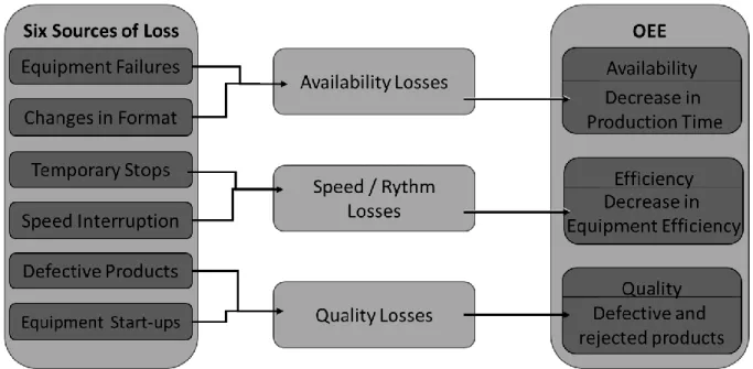
In order to achieve the improvement of OEE, for each equipment is important to identify the negative effect of each type of loss in order to prioritize strategical approaches and solve problems. Nakajima identified six sources of losses (Nakajima, 1988):
1) Loss in equipment breakdown, considered one of the main reasons towards the loss of time and efficiency in industrial facilities;
2) Losses via adjustments in the setup procedures, related to change of format; 3) Losses due to temporary stops, momentary problems in the production cycle; 4) Losses as a result of interruptions in the production speed;
2.STATE OF THE ART
41
5) Losses caused by defective products and the need to rework, time and money are necessary in order to repair defective products;
6) Losses attributed to start-up of equipment, in the beginning of the production cycle.
Figure 2.5 shows the relations between the six sources of loss and OEE.
Figure 2.5 – Relationship between the 6 sources of loss and OEE
As mentioned above, one of the strategies for TPM’s principles is to reach the goal of zero loss, zero defects and zero accidents, in order to improve the efficiency of the productive process, therefore increasing the overall competiveness among the organizations.
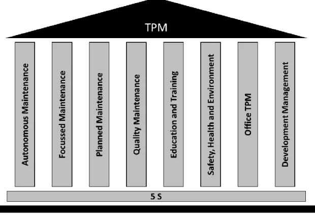
There are eight principles that sustain TPM and are referred as its pillars, represented in a house format; they require a correct sequence of introduction to guarantee the successful implementation (Nakajima, 1988). At the foundation, 5S has the purpose of reducing waste and to generate an increase in the productivity and quality through the organization of the work station. The eight pillars that support TPM´s methodology are: autonomous maintenance; focused maintenance; planned maintenance; quality maintenance; education; training; office TPM and develop management (Ahuja and Khamba, 2008). They are represented in Figure 2.6.
2.STATE OF THE ART
42
Figure 2.6 – House of TPM
TPM pursues the participation of all human resources to improve the productive availability of equipment. According to Ahuja and Khamba, TPM takes advantage of proactive and progressive maintenance methodologies, looking for the involvement of knowledge and cooperation by operators, engineers and maintenance teams to optimize the performance of the equipment, leading to the elimination of breakdowns, decrease of non-productive periods and improving product quality (Ahuja and Khamba, 2008)
3. EXPRIMENTAL WORK
43
3. EXPERIMENTAL WORK
3.1 Introduction
The internship took place at Fucoli – Somepal, SA. and had the duration of nine months, from October 3rd of 2017 to June 3rd of 2018. Along the nine months the focus was the optimization of processes occurred in the core manufacturing department of the organization, with special attention to the equipment BICOR 3300, considered the bottleneck of the operation. In the first weeks, several tasks were performed in different departments in order to understand the productive process of the company and later fulfil the proposed goal. This chapter will describe the work carried out such as a SMED study to improve setup times during the interchange of core boxes, a proposal to an autonomous maintenance plan with the aim of increasing the productivity among workers, standardization of some procedures to create consistency and provide faster and simpler training to new employees, plus some minor tasks.
3.2 SMED – Bicor 3300
The core manufacturing process is essential to the foundry because some of the products manufactured are hollow, therefore they need sand cores. This department sets the beginning of the productive process and triggers delays in the production due to:
High setup times during the interchange of core boxes; Lack of a consistent procedure from the employees.
3.2.1 Brief Description of the Process
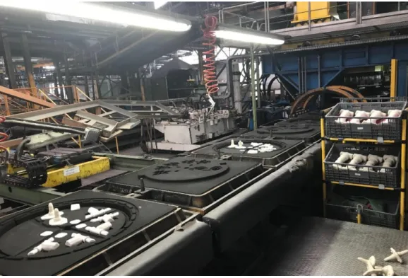
A mould box is composed by two half moulds and, after the sand cores are manufactured they are placed in one of the half moulds to create hollow products, as shown in Figure 3.1.
3. EXPRIMENTAL WORK
44
Figure 3.2 shows an example of a mould box before the top half mould (right) is rotated 180º vertically and set on top of the bottom half mould (left), where the sand cores are placed. After this step, the melted iron is poured in the top half, travels through the runners and creates one or more products.
Figure 3.2 – Placed sand cores before iron pouring
The core manufacturing department has four core manufacturing equipment to fulfil the orders placed by the headquarters and branch office:
BICOR 3300 2 BICOR 3200 BICOR 3100
The equipment are very similar to each other; the main difference is their size and the ability to produce bigger or smaller sand cores. All the equipment produce sand cores using the same cold box process that is completed in three stages:
1) filling of the core box with a mixture of sand and two types of resins; 2) fast drying of the mixture using a catalyser agent;
3) wash of the catalysing agent out with air and extraction of the core.
For this reason, the equipment has three working stations and are able to run three boxes at the same time since the stages are independent from each other, they just have to follow the
3. EXPRIMENTAL WORK
45
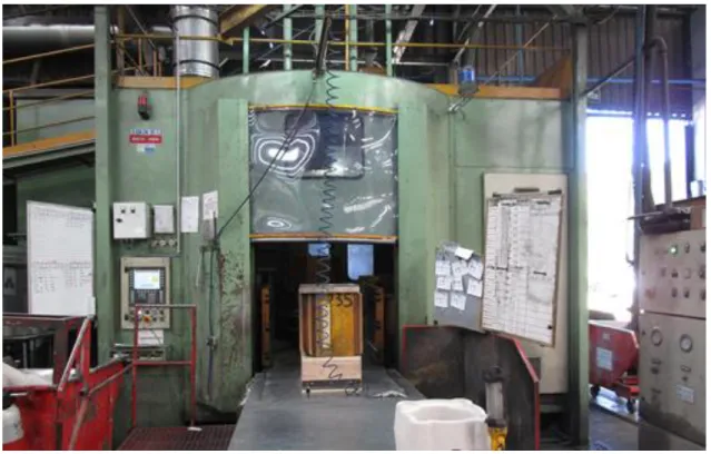
mentioned order. Each station has a set of hydraulic jaws that clamp the core boxes and allows them not to move as the table rotates to complete the three stages of the productive process. The focus of this work was BICOR 3300 (Figure 3.3), the equipment that manufactures the larger sand cores and the one that is considered the bottleneck of the operation. For numerous times, mould plates production was delayed in foundry due to the fact that cores needed were not manufactured yet. The setup times to interchange core boxes, as the production required, were high; additionally, the size and weight of some of the cores produced also made the extraction and handling a slow process.
Figure 3.3 – BICOR 3300
In this particular application, the setup times are only related to changeover between core boxes; there are no other types of format change. The main challenge was that over 200 core boxes could fit in the BICOR 3300 only, and they were different in terms of sizes, construction method, extraction method, fastening and several other dissimilarities. For this reason, the procedure was not consistent and the approach was the attempt to provide all the resources needed in order to perform the changeover.
3.2.2 Diagnosis and set of Benchmark Times
The first order of business was to measure the setup times while performing random changeovers. The method stood by the identification of each operation performed by the