Internship Report
Master in Civil Engineering - Building Construction
Green Cement Based Material Optimization for
Additive Manufacturing in Construction
Vani Basvagatha Annappa
Internship Report
Master in Civil Engineering -Building Construction
Green Cement Based Material Optimization for
Additive Manufacturing in Construction
Vani Basvagatha Annappa
Report developed under the supervision of Florindo José Mendes Gaspar, professor at the School of Technology and Management of the Polytechnic Institute of Leiria and co-supervision of Artur Mateus, Vice- Director at Centre for Rapid and Sustainable Product Development (CDRSP).
ii This page was intetionally left blank
iii
Dedication
I would like to dedicate this internship work to my parents; they always supported me in all means to educate and offer a better future. They supported me during my hard days and encouraged me to pursue my dreams and they always believed in me and boosted my confidence and gave me an opportunity to study abroad. They are my backbone and always give the advice to make me a good person and citizen in all possible ways.
My teachers from school days to university, they were always present to help in my studies and education, so I like to dedicate to all my teachers and professors in my life for helping me, directly and indirectly, to be in this position in my life.
iv This page was intetionally left blank
v
Acknowledgements
I would like to thank my supervisor Professor Florindo Jose Mendes Gaspar for his insight, mentorship, patience, accepting the new concept, supporting during the course of this internship and my graduate studies at Institute Polytechnic of Leiria (IPL).
I also want to express my sincere gratitude to Professor Artur Jorge dos Santos Mateus for allowing me to work in Centre for Rapid and Sustainable Product Development (CDRSP), guiding in practicality and providing all the necessary facilities to pursue my research.
I would like to thank the staff of CDRSP, Thomas Pimpão Marques Malho, Joa Vitorino, Ana Ramos and Margarida Carita Franco for helping, guiding, their support, patience, contribution in the internship work and helping me learn new skills and processes needed for my work.
This accomplishment would not have been possible without the support of the entire Civil Engineering Department faculty of IPL University and staff for their continuous and unwavering support both financially and professionally. Lastly, I want to thank my friends and family who have given me constant moral support and sound advice during my graduate academic career at IPL. Your support and belief have been immeasurable, Thank you.
The author is grateful to FEDER – Fundo Europeu de Desenvolvimento Regional, in the aim of COMPETE 2020 with the MOBILIZADOR PROJECT Add. Additive - add additive manufacturing to Portuguese industry (Programa-2020-FEDER-10/SI/2016 - 024533) and to Portuguese Foundation for Science and Technology (FCT) through the Project reference UID/Multi/04044/2013 and PAMI – ROTEIRO/0328/2013 (Nº 022158).
Last but not the least, I would like to thank Sika group for providing all the necessary materials and guidance to use them properly to achieve better results during this work.
vi This page was intetionally left blank
vii
Resumo
O rápido crescimento da tecnologia de impressão 3D levou ao desenvolvimento de impressoras 3D de grande escala que podem imprimir com betão. O processo de impressão 3D com betão não utiliza cofragem e portanto proporciona maior flexibilidade aos projetistas, economiza mão de obra e materiais e reduz o desperdício. Estas impressoras foram usadas para construir elementos estruturais e edifícios à escala real, que têm sido o foco desta nova era de impressoras 3D na indústria da construção.
Os materiais são uma parte importante do processo de impressão, visando a obtenção de uma mistura específica satisfazendo todos os requisitos de material cimentício. Neste campo existe o interesse para ampliar o foco nos resíduos de indústrias de construção e envolver esses resíduos na impressão 3D promovendo a construção sustentável, e combinando a tecnologia com o processo de construção.
Neste trabalho as lamas de pedra foram usadas como matéria-prima em argamassa, com o objetivo de realizar impressão 3D de forma rentável e acessível. A argamassa foi impressa usando braço robótico com um processo de impressão por extrusão. Seis argamassas com diferentes proporções de lama de pedra e adjuvantes foram testadas de forma sistemática para determinar as propriedades da argamassa adequada à impressão. A resistência à flexão e compressão das amostras impressas ou moldadas foram medidas e comparada.
Palavras-chave:
viii This page was intetionally left blank
ix
Abstract
The rapid growth of 3D printing technology has led to the development of large-scale 3D printers that can print concrete. The process of 3D printing in concrete does not use formwork and thus gives increased flexibility to designers, saves the cost of labour and materials and reduces waste. These printers have been used to construct structural elements and full-scale buildings which have been the focus of a new age of 3D printers in the construction industry.
The materials are an important part of the printing process, aiming to obtain a particular mix satisfying all the requirements of cementitious material. There is interest to broaden the focus on waste from construction industries and involving these wastes in 3D printing for sustainable construction, blending technology with the construction process.
In this work, stone sludge was used as raw material in the mortar, having the objective to do 3D printing in a cost-effective and affordable way. The mortar was printed using a robotic arm with an extrusion printing process. Six mortars with different proportions of stone sludge and admixtures were tested in a systematic way to determine the printable properties of mortar. The bending and compressive strength of printed or casted samples were measured and compared.
Keywords:
x This page was intetionally left blank
xi
List of figures
Figure 2.1: Comparison of types of 3D printing ... 9
Figure 2.2: Particle size distribution ... 16
Figure 3.1: Stone sludge sieving ... 26
Figure 3.2: Cork ... 27
Figure 3.3: Mechanical sieving of sand ... 32
Figure 3.4: Mix preparation procedure ... 33
Figure 3.5: Casting of mortar ... 33
Figure 3.6: Flexure test ... 35
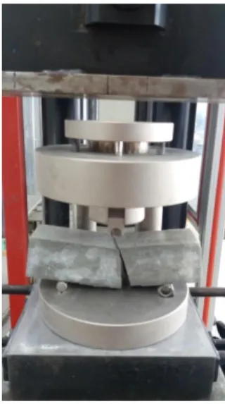
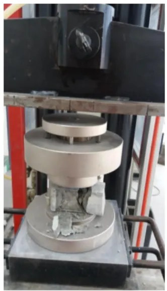
Figure 3.7: Compression test ... 36
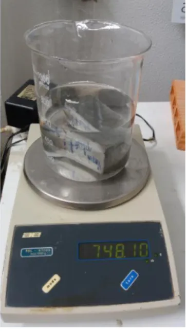
Figure 3.8: Absorption test ... 37
Figure 3.9: Twin screw extruder with an opening to introduce the material ... 38
Figure 3.10: FDM printer ... 39
Figure 3.11: Part names and working axes of the robotic arm ... 41
Figure 3.12: Base parts of robotic arm ... 41
Figure 3.13: Peripheral equipment mounts ... 41
Figure 3.14: Components and systems of robotic arm ... 43
Figure 3.15: Entire equipment assembly with robotic arm ... 44
Figure 3.16: Micro CT Equipment- Sky Scan(1174v2) ... 45
Figure 4.1: Consistency and Water/ Cement ratio. ... 50
Figure 4.2: Bending test result at 28days. ... 51
Figure 4.3: Compressive strength at 28days. ... 52
Figure 4.4: Compressive strength v/s Water/ Cement ratio ... 53
Figure 4.5: Extruded mortar. ... 57
Figure 4.6: Extrusion of mixes. ... 59
Figure 4.7: Shape retention of mixes. ... 60
Figure 4.8: Buildability of mixes. ... 62
Figure 4.9: Open time of mix M18. ... 63
xii Figure 4.11: Surface imaging of the same mix. ... 65
xiii This page was intetionally left blank
xiv
List of tables
Table 2.1: Mix proportion ... 15
Table 2.2: Compositions of various mixes ... 16
Table 2.3: Mix design of 3D printable geo polymer mortar ... 19
Table 3.1: Mixes Composition ... 31
Table 4.1: Water/ Cement ratio ... 47
Table 4.2: Consistency of mixes ... 48
Table 4.3: Density test results ... 54
Table 4.4: Absorption result ... 55
Table 4.5: Comparison of conventional & 3D printed mortars ... 55
xv This page was intetionally left blank
xvi
Table of Contents
DEDICATION III ACKNOWLEDGEMENTS V ABSTRACT IX LIST OF FIGURES XILIST OF TABLES XIV
1. INTRODUCTION 1
1.1 General Background ... 2
1.2 Objectives ... 3
1.3 Structure of the Report ... 4
2. LITERATURE REVIEW 5 2.1 History of 3D Printing ... 5
2.1.1 Types of Additive Manufacturing ... 6
2.1.2 Comparison and Discussion ... 9
2.2 Mortar ... 10
2.2.1 Properties of Mortar ... 10
2.2.2 Rheology of Cement and Mortar ... 13
2.2.3 Ultra High Performance Concrete ... 15
2.2.4 Fibre Reinforced Portland Cement Paste ... 17
2.2.5 Geo Polymer Concrete ... 18
2.2.6 Shotcrete 3D Printing ... 20
2.3 Cost Benefit Analysis ... 20
2.3.1 Circular Economy ... 20
2.3.2 Cost of printing ... 22
xvii
2.5 Comparing Conventional Manufacturing Process and AM Process ... 24
3. MORTARS AND EQUIPMENT PREPARATION 25 3.1 Materials ... 25
3.1.1 Stone Sludge ... 26
3.1.2 Cork ... 26
3.1.3 Eucalyptus Ash ... 27
3.1.4 Aluminium Polishing Waste ... 27
3.1.5 Admixtures ... 28
3.2 Mortars... 30
3.2.1 Mixes for Testing ... 30
3.2.2 Mixing Procedure and Methods ... 32
3.2.3 Tests on Wet Mortar- Consistency Test ... 34
3.2.4 Tests on Hardened Mortar ... 34
3.2.4(a) Bending Test ... 34
3.2.4(b) Compression Test ... 35
3.2.4(c) Water Absorption and Density ... 36
3.3Equipment to Print ... 38
3.3.1 At Initial Stage ... 38
3.3.2 Final Stage ... 40
3.4 Micro CT- Microcomputed Tomography ... 45
4 RESULTS 46 4.1 Wet Properties of the Mixes ... 46
4.1(a) Mixing Time ... 46
4.1(b) Water/ Cement ratio ... 47
4.1(c) Consistency ... 48
4.1.2 Hardened Properties of the Mortar ... 50
4.1.2(a) Bending Test ... 50
4.1.2(b) Compressive Strength ... 51
4.1.2(c) Density and Absorption ... 53
4.1.2(d) Comparison of Conventional and 3D Printed Mortar ... 55
4.2 Printing Results ... 56
xviii 4.2.2 Final Testing ... 57 4.2.2(a) Flowability ... 58 4.2.2(b) Extruadbility ... 58 4.2.2(c) Shape Retention ... 60 4.2.2(d) Buildabilty ... 61
4.2.2(e) Open Time ... 63
4.3 Micro- CT Scan ... 64
5 CONCLUSION AND FUTURE DEVELOPMENTS 66 5.1 Conclusion ... 66
5.2 Future Developments ... 67
REFERENCES 68
1
1. Introduction
Last few years the construction industry has encountered the influence of modern technology i.e. Additive Manufacturing (AM) also known as 3D printing. It is growing rapidly in the entire sector but in construction lot of work yet to be carried out and it allows chain manufacturing and supply of the 3D products and prototypes.
Additive Manufacturing allows enlarging the range of construction by printing large-scale buildings and structural components. The professor Berokh Khoshnevis [1] developed “counter crafting” to construct house through gantry system by depositing thick layers and smoothening the outer surface using the trowel. Enrico Dini [2] a civil engineer from Italy invented “D Shape” technology in September 2007; it uses huge gantry system for printer movement and method is the combination of powder bed and binder jetting techniques for gigantic printing. In 2014 Chinese construction company Win Sun Decoration Design Engineering Co [3], successfully build the house using 3D printing, the structural components were prefabricated in the factory and assembled at the site and later in a year they managed to construct five storeys building using the same technique. Similarly, Dutch Dus Architects [3] are planning to construct a canal house in Amsterdam using 3D printing; it is the 1st project in Europe. These examples illustrate the perspective and practical nature of 3D printing in realistic construction.
AM is a solution to some of the challenges in construction [4]: safety of workers at the site and from the harsh environment, no special skilled labours, low waste generation, less transportation expense, low cycle, production time and cost. The main challenge of 3D printing in construction is material properties, developing the composition suitable for printing and exhibiting the properties that of conventional material in construction. According to author MA Guo Wei at.al [4], the solution to the above mentioned challenges are aspired by few researchers Gibbons et.al, Maier et .al, Xia and Sanjayan and Khoshnevis et.al, they experimented on few cementitious materials and have their own mix design for 3D printing.
This internship focuses on optimizing the mortar for 3D printing utilizing the waste from various industries. There are several industries generating waste and this should be taken care otherwise it will lead to serious health problems and environmental issues. We
2 tried to utilize such waste in the work to make the new technology more sustainable and economic for our future.
3D technology in the construction industry is growing at greater phase, but yet there is no perfect composition/mixture which satisfies the requirement of the conventional way of construction and performance. So the report illustrates the work on various cementitious materials and their behaviour under various circumstances.
1.1 General Background
Till now additive manufacturing was adopted in highly commercial sectors such as aeronautical and biomedical due to expensive raw materials and technology [5]. As per the world’s leading information technologic company Gartner, 3D printing has both advantages and disadvantages. They believe that five newly emerging technologies will change the business before 2020. The 3D printers used now a days have the ability to customize the design and cycle development as per the needs of individual in order to communicate and to find the solution for design in engineering [6].
AM is growing at a faster phase from past 25 years in various industrial domains but lagging in building construction sector in terms of technology and innovation. Our current process is labour dependent with a simple and systematic approach requiring formwork to support components. Present design and complexities involved in constructions are exposing the workers to the unhealthy environment [7].
AM had two classical methods powder bed and inkjet head printing (3DP) and fused deposition modelling (FDM), where cement as a binder in between sand layers. Trial and error is practiced by many companies and institutions for large-scale construction using the above mentioned methods that varying in terms of ingredients and applications [5].
At present, there are two major types of concrete printing technologies at large scale: i.e. D shape and counter crafting [7].
As per Labonnote N et.al “3D printing” refers to the various processes used to synthesize a three-dimensional object [6]. AM gives detail idea on how the part is manufactured purely on a digital process. AM provides a new room for complexity free manufacturing by considering design freedoms and parameters [8].
3 Additive manufacturing is defined as a process of joining materials to make objects from 3D model data, usually layer upon layer, as opposed to subtractive manufacturing methodologies, as per ASTM F2792-412a [9].
“Construction” defined as the process of generating high or large structures by linking small structural element; they may be residential houses, bridges and other types buildings.
AS per Labonnote N et.al [6] “Additive construction” is a similar to “additive manufacturing” which can be described as “the process of joining materials to create constructions from 3D model data”. This allows assembly of the processes such as design and production through digital means to a certain extent.
1.2 Objectives
The major objective of all institutions, researchers and companies is to find answers to the following questions which are of major interest. The answers to these questions will bring evolution in the construction field.
•what construction-specific material science challenges do we face?
•what structural challenges come into play during scaling up additive manufacturing? •what building design opportunities emerge when using additive construction?
•what are the requirements for a successful (marketable) concept for use in the building industry [6]?
The objective of the work is to find solutions for the above challenges which involve finding the optimal composition of the materials, for better performance, strength and ease of printing in construction.
This research, “Green Cement-Based Material optimization for additive manufacturing in construction”, aims to enlighten and highlight how 3D printing can benefit the construction industry and to achieve the mix using industrial waste for 3D printing. This research aims to accomplish the above mentioned objectives by preparation of samples, testing and analyzing the results. Some benefits that could arise as a result of this research are:
4 • Incorporation of industrial waste
• Autonomous construction
• Elimination of formwork in the construction industry • Reduction in labour and construction cost
• Reduction in construction time • Reduction in waste
1.3 Structure of the Report
This report is divided into 6 main chapters and each title has certain number of sub- titles. The main titles are Introduction, mortars in additive manufacturing or bibliography, mortar and equipment preparation on testing, experimental results, conclusion and future developments:
Chapter 1: Introduction
It gives a brief idea about the concept of work, definition of the concept, and objective of the internship.
Chapter 2: Literature Review
This chapter provides an extensive review on history of 3D printing, types, the mortar used in past and present, cost analysis of this technique, advantages and disadvantages and comparison of methods used in Construction sector.
Chapter 3: Mortar and Equipment Preparation
This chapter explains various raw materials, methodology, procedure of conducting the tests and types of printers and equipment’s used.
Chapter 4: Results and Discussion
The analysis of results obtained after testing and discussing possible results and reasoning of such results.
Chapter 5: Conclusion and Future Developments
This chapter concludes the internship objective and provides future work recommendation.
5
2. Literature Review
This chapter explains the various work carried out in past and present in civil engineering academics using mortar and concrete in construction using additive manufacturing or 3D printing. The history of the 3D printing from 1986 and how it has evolved over time in the 21st century and how it has been used in civil engineering and construction industry.
2.1 History of 3D Printing
Chuck Hull considered as the father of 3D printing, an American engineer and co-founder of 3D systems in 1986. He invented the stereolithography apparatus which enabled objects to be formed by the interaction between lasers and photopolymer resin [10].
The next invention was Fused Deposition Modelling (FDM) by Scott Crump, the co-founder of Stratasys Inc., in 1989. Later in 1992, the Selective Laser Sintering (SLS) was invented.
As time passes, improvisation is default in every technology, so as in 3D printing industry. At present research teams are printing product with various materials such as plastics, metals, ceramics, paper, food and concrete further moving towards large-scale components without formwork [11].
Freeform construction
Buswell et.al [12] defined freeform construction as “processes for integrated building components which demonstrate added value, functionality and capabilities over and above traditional methods of construction”.
Freeform construction is auto - mechanized by robots attached to the crane system for constructing structural components. As this method is free of formwork UHPC1
1 UHPC- A cementitious composite material with water/cement ratio lower than 0.25 and higher percentage
6 High-Performance Concrete) which used in construction and thus develops significantly higher mechanical properties than Counter crafting project [12].
2.1.1 Types of Additive Manufacturing
There are various types of 3D printing techniques being used in various industries for additive manufacturing and these techniques are explained briefly. The main focus is on the techniques that are used in construction industry and 3D printing of cementitious material.
The additive manufacturing is broadly classified into two categories; they are extrusion printing and powder printing.
Extrusion printing
The extrusion printing is equivalent to fused diffusion modeling (FDM) method which extrudes cementitious material from a nozzle mounted on a gantry/robot to print the structure layer by layer. This technique was designed for onsite construction application such as large-scale building components. Counter crafting is an example of extrusion printing developed by Khoshnevis and concrete printing designed by Lim et.al. [13]
Powder printing
It is also known as powder based three-dimensional printing; this technique binds powder by depositing liquid in such a way that it can create complex design and geometries. The designed components are produced away from the site basically; it is used to manufacture precast components. The typical examples are the D shape technique and emerging object [13].
It has thin layers which are closely packed with each other and spread on the platform, each powder layer can be glued by a binder or by using a laser. Each successive layer is glued together until the 3D part is generated. The factors such as size distribution of powder, the density of the part and packing plays a vital role in the efficiency of this method [14].
The advantages of this method are fine resolution and high precession in printing quality, so it can be used for complex design. The part is supported by surrounding powder, which can be removed after completion of printing and can be used again, but it is expensive with the slow process taking a longer time to print [15] [16][17].
7 Types of 3D printing and their techniques are explained briefly:
Fused deposition modelling
A thermoplastic polymer is used in FDM to 3D print layers by using a continuous filament, this filament should be in semi-liquid state at the nozzle for extrusion of material and filament is heated at the nozzle to glue on previously printed layers. The mechanical parameters of the printed parts depend on the layer thickness, width and orientation of filaments [18]. The main cause of failure of printed parts is mechanical weakness due to interlayer bonding [19]. The other weakness along with mechanical properties is poor surface finish on the other hand it’s fast being low cost and simple process compare to others [20].
The main challenges in FDM are bonding between layers, the formation of voids while printing and orientation of fibers [21, 22]. The latest FDM systems include two nozzles, one for the part material and another one for the support material. It is used widely in printing ceramic components due to its low cost and simple technique [23].
Stereolithography (SLA)
Developed in 1986 and one among the 1st used additive manufacturing process [24]. It is also known as photo-polymerization as it uses UV light to start the process and the component is formed in a liquid polymer in slices from top to bottom which hardens in UV radiation [23]. Monomers can be used to print ceramic-polymers; while printing the solidified part which acts as support and the remaining liquid is removed [25]. Stereolithography is a slow process with limited raw materials to print which makes the process expensive [23, 24].
Direct energy deposition (DED)
This method has different names: Laser Engineered Net Shaping (LENS), Laser solid forming (LSF), Directed Light Fabrication (DLF), electron beam AM and wire +Arc AM. DED is used to produce high-quality superalloys by using source of energy on the substrate and inserting melted material at the top [26]. This method can be used as an alternative to powder bed as it can fill cracks and repair manufactured parts at multiple axes at the same time [27]. It is used for less complex components, so it has low surface quality and it is relatively slow compared to SLS and SLM. It can be used in automotive and aerospace to repair some parts [16, 26].
8
Laminated object manufacturing
It generates components by slicing and laminating of sheets or materials layer by layer and commercially used additive manufacturing method [28]. It is used widely in industries such as electronics, paper and smart structures due to reduced tool cost and manufacturing cost for large structures, as it gives room to use a variety of materials like polymer, ceramics, paper and metal-filled [28,29].
Ink jetting, counter crafting and D Shape
It is a highly efficient method for additive manufacturing of ceramic at a faster speed, complex design and flexibility of printing [24]. Two main types of ceramic inks are wax based inks and liquid suspensions [25]. Counter crafting is similar to inkjet but used for bigger concrete structures with large nozzles under high pressure [30]. This technique was improvised by using a trowel to smoothen the outer surface during extrusion. The layer at bottom act as support for upcoming layers and it uses a crane for onsite applications. It was developed to overcome the speed in construction and longer duration required by humans and to minimize the material use [24, 30, 31, 32].
The layers of desired geometry can be printed using D shape it is similar to powder deposition and Z-Crop 3D printing process [25]. It can produce components of 1.6m high, once the printing is complete it is dug out and the remaining powder is removed [31].
The techniques in additive manufacturing are also classified into the following categories:
a) Concrete layered overlay: counter crafting and concrete printing, extrusion of concrete and self- stabilization.
b) Sand powder- layered adhesive stack: layers were bonded using selective liquid agent. D shape is an example.
c) Mechanization: This method uses robots for printing and uses various materials (brick, metal and plastics) along with the concept of robotic fabrication [33].
9
2.1.2 Comparison and Discussion
The above section gave a brief description of various types of printing techniques. There are many processes which are similar to each other but they differ from each other depending on the purpose of use.
Here the discussion is based on the cementitious processes:
D shape has long print speed resulting in a poor finish with material waste but allows freedom to create components. The hybrid system allows integration of specific manufacturing process involved.
Concrete additive manufacturing also seems to allow freedom of shape control however; it does not have a smooth or neat surface finishing. This method of manufacturing was to be used in combination with a flexible moulding system; the substantial post-processing would be required to get smooth results.
Counter crafting gives very smooth extrusion results by using proper trowels on other hand the use of weaker mortar materials is only disadvantage over 3D concrete printing [26].
While comparing hybrid and flexible mould system, D shape technique has its own support unlike counter crafting and 3D printing which have higher potential.
10
2.2 Mortar
2.2.1 Properties of Mortar
The conventional way of construction is one among the oldest additive construction i.e. using brick and mortar to bond the layers can be considered as an additive manufacturing before 3D printers [6].
The fresh concrete in additive manufacturing plays a vital role during printing. In order to print few parameters of fresh mortar should satisfy the following properties [32] : I Pumpability - The ease with which material can move through the system at constant pressure.
II Printability - Possibility of printing the material with respective depositing device III Buildability - Withstanding its own weight in the fresh state without failure and deformation under self-weight.
IV Open time - The amount of time the material is possible to be elastic and possible to achieve the above-mentioned properties.
There is a patent for 3D printing powder composition and methods of use by Ronal RAEL from University of California on 2011-09-20.
A powder composition for 3D printing, comprising as per the patent for concrete and other cementitious material as per claims 15 [34]:
(a) Approximately 0.75 to 2.0 parts (from 10) by weight of an adhesive material. (b) Approximately zero to 2.0 parts by weight of an absorbent material.
(c) Approximately 4.0 to 6.0 parts by weight of a base material.
Relevant materials for additive construction comprises of the combination of paste and bulk materials. The paste usually consists of cement and superplasticizer but bulk materials as follows:
Natural aggregates such as soil, sand, natural gravel, crushed stone, clay or mud.
Recycled aggregates such as those from construction, demolition or excavation waste.
11
Natural fibers such as cellulose and recycled wood fiber [6].
According to author S Lim et.al [32] for large-scale construction like walls and facades which require high-performance mortar comprising of 54% sand and 36% cement and 10% water by mass, each mortar has selective properties based on mix design. As per Pshtiwan Shakora et.al [35] to build a wall of 10 mm height, the composition used was 28% cement, 60% sand, 7.97% fly ash and 4% silica fume with 232 water.
In order to print the mortar, it should satisfy certain properties, so that it can be printed continuously, smoothly and to attain the required strength. The mortar should satisfy the following properties:
Flowability - Smooth transfer of mortar from the storage system to extrusion system without any blockage and at constant air pressure. As per Guowei Ma [36] and other researchers flowability at the site can be measured by slump test.
Extrudability - It depends on particle size distribution and mixing procedure in the dry state. It is considered one of the important parameter while printing and also referred to as extrusion of material from the nozzle and pipe continuously without the development of cracks and breakage while printing [36].
Biranchi Panda and Ming Jen Tan [37] explained the influence of yield stress2 on extrusion, higher the yield stress more difficult in extrusion resulting in a discontinuous filament. Guowei Ma [36] et.al discussed if the filament extruded is long for a certain distance without any separation and opening gaps between each filament deposition without any liquid drainage and clogging of the system and which can be referred as better and smooth extrusion.
Yield stress and viscosity of the material is governed by particle size, gradation, surface area; paste/aggregate volume and as per literature review few tests such as flow table test and drop test were performed in the past to determine the flow behaviour which helps in the extrusion of the material [37].
Shape Retention - is explained by Biranchi Panda and Ming Jen Tan [37] is the ability of the material to retain its shape after extrusion as per the design and an equation to calculate Shape Retention Factor (SRF) which is a dimensionless quantity:
2 Yield Stress- Cement surface get adhered by Superplasticizer, limiting the interaction and strength
12 SRF =
Material with low slump shows high SRF; mortar should have high yield stress to withstand its own weight while printing but it should be within limits, SRF and stress factor exceeding the limits making an extrusion of the material difficult.
Buildability - Even though 3D printing advancing in construction but buildability is still an issue which needs special concern, as the freshly deposited material should be able to resist the upcoming layers and their weight without falling or breaking [37]. Still, research is going on to scale up the size and stack the material in the vertical direction. It is a critical parameter to evaluate the printability of the mortar which in turn evaluates the performance of extrusion and deposition of wet material and behaviour under load [36].
Open Time - is defined as the duration in which the material remains in the fresh state with good workability for printing [36]. Sometimes open time is confused as the setting time of the mix, but it is the time in which the material can be extruded and is smaller than the setting time of mix [37]. It can also be referred to as the time period in which the fresh mix possess good extrudability and it can be measured by Vicat apparatus or flow test.
As printing have certain speed and time, the deposited material should have enough time to initiate the chemical activity necessary to have better bonding with successive printed layers but if the waiting time between each layer is too long which leads to development of cold joints as a result development of weak bonding between filaments and reduction of mechanical strength as the waiting time increases. Open time should be such that it balances between cold joints and crack development in filaments [36].
Relationship between extrudability, buildability and printability
Guowei Ma et.al [36] derived the relationship between extrudability, buildability and printability. The extrudability is dependent on the flowability and early age stiffness. Extrudability is directly proportional to the flowability and stiffness of the material, flowability was characterized by spreading diameter (Ds) and it is dependent on time (t). The extrudability coefficient can be defined as the ratio of spreading diameter (Ds) and time interval t.
13 Material with low slump can have better shape retention property and if the penetration resistance is high then it can resist the upcoming loads. Hence, the buildability is directly proportional to penetration resistance (Pr) and slump (Hs). Thus, the buildability is define by the ratio of penetration resistance (Pr) and slump (Hs)
In general optimizing design of printability relies on the balance between the extrudability and buildability [36].
The extrudability is inversely proportional to rest time, whereas the buildablity increases with time. It was observed that the better the extrudability, the worse the buildability and vice versa.
2.2.2 Rheology of Cement and Mortar
Mikanvoic and Jolicoeur [38] explained the effect of superplasticizer (SP) on the fresh cement-based material to improve their rheology. Superplasticizers nowadays used in cement in order to improve the workability at given water /cement ratio or on the other hand they allow the same workability to be obtained as that of plain cement with a great reduction in water content.
Jianwei peng [39] measured the effect of superplasticizer on the rheology fresh cement asphalt paste. He used “RheoPlus QC” coaxial cylinder rotary rheometer to measure the rheology of the cement paste. Later he explained the mechanism that the SP absorb the surface of cement grains and disperse the flocculated cement. After being mixed with water, cement grains being hydrated consequently by developing a heterogeneous charge distribution on the surface hydrating cement grains. The observation shows the advantages of SP by decreasing yield stress and viscosity of cement paste with cationic emulsion and an increase of SP show the same results irrespective of the type of cement.
14 The rheology of fresh cement paste is mainly dominated by the interaction of cement particles which may adsorb SP molecules.
As per R.J.M Wolfs [40], 3D printing material can be low to zero slump and it should maintain its shape during printing and after deposition. The material should be able to carry its own weight soon after printing and this characteristic is known as Green strength, which is dependent on interparticle friction and cohesion between particles.
Yu Zhang [41] used rheometer to study the thixotropy, viscosity and yield stress. Except the thixotropic behaviour, the buildability of the 3D printing concrete materials was significantly related to green strength. There is a relationship between the green strength, structure re-build (thixotropy), yield stress and buildability of the concrete. The deposited material tends to fail by developing cracks, deformations and collapsing of the component when the yield stress coincides with the force equal to crack development. So geotechnical tests were conducted to assess the properties of early age printed concrete.
Jae Hong Kim [42] explained the behaviour of the cement paste under high pressure, the material at the centre experiences maximum velocity and less near the surface of the pipe. Pumping can affect the rheology of the material and the measured yield stress of the paste at a different water/cement ratio and that represented in a graph indicates the thixotropic effect. Increase in the yield stress with a decrease in water/cement ratio and the samples of water/cement ratio 0.35 and 0.40 experienced 15% reduction in the yield stress when the pressure is greater than atmospheric pressure.
The samples with high water/cement ratio did not experience any significant pressure effects. Theoretically, the yield stress of the cementitious material is proportional to interlocking force between solids. The material with lower water/cement ratio has smaller yield stress at high pumping pressure due to the presence of flocs or coagulated solids. If the pressure is steady then the rheology of the material is the same over the investigation period. Thixotropy of the sample is sensitive to both atmospheric pressure and high pressure.
15
2.2.3 Ultra High Performance Concrete
At France University for ultra-high performance concrete, the 3D printing premix prepared was composed of Portland cement CEM I 52.5N (30 − 40%w), crystalline silica (40 − 50%w), silica fume (10%w) and limestone filler (10%w). The water /cement ratio was calculated for entire mix using w/(c + s) = 0.1, the ultra-high performance and self-placing mortar3 was mixed with polymer-based resin in order have quality adhesion between printed layers. Wall element of 139 layers with dimension of 1360x1500x170 mm printed in 12 hours weighing 450 kg. The component was designed for Acoustic and structural performance [5].
Ingrid Paoletti [43] gives brief, how additive manufacturing has evolved in architecture by providing freedom of design in construction components and room for complex components. In the corresponding work, the mix was made up of two clays such as 58% red earth, chamotte red 20% and the setting time was extended by using 1% sodium carbonate into 21% water. Bricks with architectural designs were printed in 4 hours and backed for 9 hours. Tested for absorption and structural resistance and in turn the absorption was similar to traditional bricks and had better structural resistance.
Weng et.al [44] used Ordinary Portland Cement, silica fume, silica sand, fly ash, natural river sand, water and superplasticizer. To study they prepared five mixes with various sizes of silica sand and sand and the mix design for the mix is listed in Table2.1.
OPC Sand W FA SF SP/(g/l) 1 0.5 0.3 1 0.1 1.3
All the ingredients content are expressed as weight proportion of cement content
Table 2.1: Mix proportion [44].
The particle size of sand and silica sand are represented in the graph in Figure 2.2, the sand size bigger than 1.2 mm was not used but four different sizes of silica sand were used 0.6-1.2 mm, 0.25-0.6 mm, 0.15-0.25 mm and less than 0.15 mm. A cylinder of 11 cm
3
16 diameter, 2 cm thickness and height 50 cm with 50 layers was printed. The printed element was deformed at the 30th layer but in the last trial, they were able to print 80 cm height without any deformation [44].
Figure 2.2: Particle size distribution [9].
Viscosity modifying admixture (VMA) was used to obtain Ultra-high performance concrete (UHPC) by using nano clay, fibers having a length less than 6mm and densified silica fume as supplementary to cement, in addition it improves cohesion in the fresh state that helps in developing mechanical strength thereby reduces the permeability of hardened concrete. Few laboratory tests were done in order to characterize fresh properties of mortar for 3D printing and evaluation of printing mixture. Print quality, shape and cylinder stability was tested for these compositions listed in Table 2.2 [9].
% Percentage are reported by cementitious materials mass Table 2.2: Compositions of various mixes [9].
17 To print a reinforced concrete beam, water/cement ratio was restricted to 0.39, 4 mm of aggregate, 0.5% polypropylene fibers were used to prevent early age shrinkage. Presence of fibers makes concrete more stiff, hence to make it more viscous polycarboxylate superplasticizer was used to attain the balance of the material pumpability. 3 m long beam with rectangular cross section 0.60 m and 0.45 m designed which was divided into 5 segments. Each segment was printed separately and was joined by rebar at the end. The beam was subjected to 3 point bending test and the initial flexure stiffness was comparable to normal reinforced concrete beam [45].
The concrete material designed to overcome certain printing constraints:
The cementitious material should be viscous enough in fresh state so that it can be extruded from nozzle smoothly and buildable.
The printed mix should poses high strength for omission of possible weakness due to connection between successive layers.
The maximum diameter of aggregate should be lower than nozzle and extrusion head.
2.2.4 Fibre Reinforced Portland Cement Paste
Scaffolding was done by 3D printing in that two main materials are Ordinary Portland Cement (OPC) and Calcium Aluminate Cement (CAC). The mixed ratio contains 67.8% CAC, 32.2% of OPC and 4.5% of the total mix was replaced with lithium carbonate as an accelerating agent and Zb60 containing humectant and water. Specimens were printed in different sizes and shape to study compressive strength, porosity and surface roughness [46].
In this study infill mortars4 are used for specimens and the composition of the mix is 61.5% cement, 21% silica fume, 15% water and 2.5% water reducing agent in order to keep low water-cement ratio 0.3 and 0.3% hydration inhibitor. A mix with 40% cement and 60% sand with water cement ratio of 0.4. To distribute fibers uniformly in the mix, they were added at the end and mixed at 50 rpm. Few paths were designed to print
4
18 mentioned mixes and tested their bending and compressive strength, density and porosity. According to author steel reinforcement was necessary to achieve higher strength [47].
The reproduction of the plinth5 by fiber reinforced concrete and the composition was 1:1 sand : cement ratio, 0.3 water-cement ratio and 0.1% micro polypropylene fibers, including 1.25% of water reducer [64]. Department of Functional Materials in Medicine and Dentistry tried to incorporate fibers along with gypsum and the fibers used are Polyacrylonitrile fiber fillers (PAN), polyacrylonitrile shortcut fiber (PAN-sc), polyamide fiber fillers and glass fibers. The fiber content of 1% was used along with self-setting polyurethane resin for a depth half of the sample [48]. Singapore centre of 3D printing used chopped glass fiber in 3D printing with different composition but they restricted the content of fibers up to 1% to avoid clogging to achieve smooth, continuous extrusion during printing process [49]. Fiber alignment is also influenced by the extrusion pressure, fibers parallel to loading direction acts as voids and perpendicular fibers are intact under high pressure by increasing density.
China University tried to use copper tailings as a fine aggregate with partial replacement to sand and keeping few raw materials constant: cement, silica fume, fly ash and fibers. Six mix proportions were tested from 0 to 50% replacement of sand, reducing the water quantity by 30% and a solid content fraction of 37.2% are adopted in order to achieve the flowability for the mix. They studied wet and hardened properties of the mix such as flowability, extrudability, buildability and open time by printing, but hardened properties were tested on prisms of the above mix [36].
2.2.5 Geo Polymer Concrete
The primary raw material of geopolymer is fly ash, silica fume and ground granulated blast furnace with geopolymer binder. Singapore University used five different mix proportions, but the proportions were random in order to check the extrusion of the material and later the most suitable mix proportion was improved by adding fibers. Later the same author performed an experiment in order to achieve the proper mix proportion of geopolymer paste for 3D printing. The composition is listed the Table 2.3 [49].
19 Materials Weight by percentage Fly ash 27.85 Slag(GGBS) 1.68 Silica Fume 3.36 Sand 49.55 Potassium Silicate 12.5 Water 4.16
Table 2.3: Mix design of 3D printable geo polymer mortar [49].
Maryam Hojati [50] and team participated in a competition organized by NASA to produce an indigenous material for construction on Mars. Materials used for the work follows the rules and regulation for the competition and restricted to use uneconomical materials. The material used was geopolymer and few chemicals to reduce the amount of water. They used both cement and cement free mortars of different mixtures but they presented the mixture design which satisfied the NASA requirements and was successfully extruded. They used basalt and river sand as fine aggregate passing sieve number of 16 (1.19mm). Firstly, they used OPC and water but they didn’t use this mixture as it fails to satisfy the NASA requirements which motivated them to use geopolymer concrete. Martian soil, sorel cement or magnesium oxychloride cement and Polypropylene fibers were used in the second trial as they are alternative to ordinary Portland cement mortar. In the third trial, they incorporated metakaolin or fly ash in geopolymer concrete and calcium to accelerate the setting time at room temperature [50].
20
2.2.6 Shotcrete 3D Printing
Digital Building Fabrication Laboratory of TU Braunschweig in february 2018 printed using shotcrete method with robots, called shotcrete 3D printing [51]. The Institute of Building Materials, Concrete Construction and Fire protection (IBMB), is trying to develop a mixture suitable for digital fabrication by shotcrete method. This technology allows the frameless construction of the complex structure, thereby producing high-quality products with minimum resources as per the designs. This method uses robotic arms that perform shotcrete and stabilization of formwork.
Ibrahim O. Huthman in his master thesis explained the possibilities of using shotcrete in additive manufacturing, as they have few similarities. Both adopt ultra-high performance concrete in their application with similar machine that has pumps to push/print concrete at the nozzle. Observing these similarities he deduced that 3D printing of concrete can have innovation with shotcrete methods [52]. Stellenbosch University produced concrete materials for shotcreting, where they used calcium alumina cement replacing of standard cement types for printing by robots [53].
2.3 Cost Benefit Analysis
The cost plays a vital role in every field and the same with 3D printing and its components. This section explains how the cost is considered in the circular economy and the details of cost by a 3D printing company.
2.3.1 Circular Economy
3D printing is compatible for the circular economy by reducing the material wastage and utilization of minimum material rather than subtractive method of production and has significant contribution in different ways to the circular economy system such as reuse, remanufacturing and recycling of materials and products.
21 The additive manufacturing evaluation for the circular economy can be classified into two types: 1st is to evaluate the additive manufacturing with the conventional method and analyzing the various situations in which this method is effective in terms of cost, 2nd is to determine possible resource used in respective steps while producing components. This helps to keep track of each process and to identify the consumption of resources and to control the waste where ever it is possible. In cost analysis there are two types they are: “well-structured” and “ill-structured” and the inventory comes under each kind are labour, material and machine for the well-structured failure of the components and cost of machine system under ill-structured [54].
In additive manufacturing, labour work is to refill the material and operate the machine and software and in this method, the amount of ill-structured cost is least and most of the time hidden there by a reduction in the list of inventory usually the main reason of cost in production and manufacturing. In 2011 the amount of money spend on inventories was 10% of the revenue in that year and it was around $537 billion, so additive manufacturing has the ability to reduce this expenses, as components can be produced or generated as per demand and can be customized.
Nazi et.al. [55] explained how in business cost estimation plays vital importance if the price is overestimated then it affects the sales of the product and similarly if it is underpriced leading to financial losses in the business.
In additive manufacturing, the integral part is the machine and it’s about 74% of the entire construction cost followed by materials and time is an important factor which impacts the results [56]. As the method is still new in the market and in construction, the printers used for printing are expensive than traditional construction. This can be sorted out if the new technology is used in a proper way with strategies; planning and execution like control on the deposition rate which in turn reduces the cycle time, human resources and machine cost thereby reducing construction cost as per Roland Berger [57] the cost will drop in future.
1st Russian 3D printing company “Apis Cor” [58] gives their construction economics as per the work carried out in the past. They compare the traditional construction with 3D printing, and they are:
1. The quality of the construction is much better as it eliminates human error and overcoming the limitations of human inadequacy.
22 2. Cost reduction in the construction of buildings with more complex and unique design- as volume plays an important role during construction.
3. Less human dependency hence resulting in less expenditure on servicing personnel, insurances, taxes, hospital and so on.
4. Faster and reliable than humans and working continuously without break.
5. Restriction on material utilization, logistic and no labour for formwork installation. 6. In the course of construction, there is no waste or debris, which would require removal form construction sites and recycling.
2.3.2 Cost of printing
The major factors on which cost depends are the configuration and thickness of the wall, grade of mixture and location of the construction to determine the price to print 1 . The exact value can be calculated only on the basis of a building project.
The main type of building structure is done in the form of two rectilinear layers connected with a sinusoidal bridge. In this embodiment of 1 wall thickness is 300 mm requires 0.093 of printing mixture. To date the cost of construction calculated to be 6000 (82.6€) to 9000(123.39€) rubbles per [58].
At present additive manufacturing and 3D printing is expensive due to the high cost of equipment, materials and time. The printer available in the market is designed for particular material as per the producer and these materials are usually expensive due to certain properties they possess such as adherence to harden and give better finishing. We know in business time equals money, if the process is slow then the cost of products and components is high (number of machines, availability of materials and availability of time) [59].
23
2.4 Advantage and Disadvantages
As we know every coin has two faces, so do additive manufacturing. It has merits and demerits and they are discussed as follows:
Advantages of AM:
Apart from the enormous time and cost savings, AM has several advantages they are:
It gives freedom of design to designers and it can be delivered quickly from CAD documents.
Errors are reduced from incorrect designs; designs to prototype iterations are faster.
It works without a skilled machinist to prototype from the CAD model.
With appropriate materials, the model can be utilized as a part of consequent assembling operations to create the final parts. This also serves as a manufacturing technology.
By AM technology, tooling can be produced in a shorter time. This helps in bringing the products to the market at a lesser time.
Drawbacks of AM:
AM technology still cannot fully complete with conventional manufacturing, especially in the mass production field because of the following drawbacks:
Size limitations: The materials used in AM lack mechanical strength which does not allow producing large size object. Large sized objects also often are impractical due to the extended amount of time needed to complete the build process.
Imperfections: Produced parts possess rough and ribbed surface and appearance of the final product is unpleasant and unfinished look.
Cost: The equipment is expensive and involves high investments at the beginning and the materials required to print are another operational cost, so basically it is an expensive process with huge investment.
24
2.5 Comparing Conventional Manufacturing
Process and AM Process
This section gives a brief comparison between conventional and additive manufacturing process in general to get a clear vision for choosing better one.
Material efficiency: Additive construction unlike subtractive manufacturing resulting in the lower waste generation and if the waste is generated can be reused.
Resource efficiency: AM does not require these additional resources. As a result, parts can be made by small manufacturers that are close to customers. This presents an opportunity for improved supply chain dynamics. Conventional processes require high resources such as machine tool, cutting tools and coolants.
Part flexibility: No compromise in detailing of part for the ease of manufacturing, and possible to build a component with variation in mechanical properties along the various sections, thereby an opportunity for design and innovation.
Production flexibility: The quality of component is based on process, not on operator skills and it won’t need additional expensive machine so it is economical. As such, production can be easily synchronized with customer demand [60].
25
3. Mortars and Equipment Preparation
This chapter describes the raw materials used, mix preparation, mixes composition, the procedure of tests on hardened samples, preparation of the equipment and mixes prepared for printing.
3.1 Materials
Selections of the materials were done referring to various bibliographies on 3D printing in construction and works that have been carried out in past few years. The main component of the composition is portland cement, as cement is one of the major materials used in construction for ages, due to its properties. The detailed mix proportion will be discussed later in this section
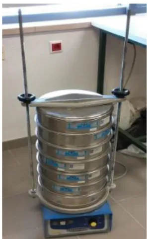
We tried to use various materials in order to optimize the mix for 3D printing. The ordinary Portland cement (CIMPOR CEM II/B-L) act as a binder, fine sand passing 500µm-250µm was selected, as the nozzle of the printer could not print the particle of bigger size than 500 µm.
Keeping sustainability into mind we tried to incorporate wastes from varies industries such as stone sludge from a nearby quarry, cork, eucalyptus ash and aluminium polishing waste. In order to reduce the amount of water and make the mix pumpable, buildable and plastic during printing; few admixtures were used, as follows Viscocrete 20HE, Frioplast P, Sika Control 40, Plastiment VZ, Viscocrete650DUO and Sigunit TM and in order to reduce the shrinkage of the mixture during its early stage the fibers were used.
26
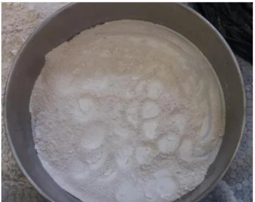
3.1.1 Stone Sludge
Stone sludge is one of the wastes generated in huge quantity at quarries. The powder obtained during the cutting and polishing of dimensional stones is called stone sludge shown in Figure 3.1. Usually, the waste from the quarry comes in two forms i.e. powder and sludge. Powder-dust is generated while blasting and grinding but sludge is obtained while cutting and polishing as this procedure involves a huge amount of water. This waste is being dumped into a landfill which causes environmental issues and health problems in the neighbourhood. So, many of the researchers and engineers are trying to utilize/incorporate this waste to make the useful product so, we incorporated it into the mix as a replacement to sand.
Figure 3.1: Stone sludge sieving.
3.1.2 Cork
Usually, cork in construction is used as insulation material shown in Figure 3.2, in facades, roofs and flooring. As we know cork is organic, renewable in nature and it’s a green material, so we decided to study the behaviour of the mix with cork and pure cork of size 0.1mm was used. The main idea of using cork is to produce concrete with insulating properties which prevent additional thermal insulation in facades and other parts of the structure.
27
Figure 3.2: Cork.
3.1.3 Eucalyptus Ash
The utilization of eucalyptus twigs for generating heat/burning in various industries are the main reason for the generation of ash. Even the eucalyptus oil refineries produce wastes which can be used. In this work ash from the industry was used which possesses little bit of pozzolanic properties and allow the replacement of cement up to a certain percentage. Many researches and works have been carried out using this particular waste in concrete, but not yet used for 3D printing.
3.1.4 Aluminium Polishing Waste
Aluminium is the 3rd most abundantly available resource on the earth and it goes through various processes till it reaches the final product. Every process produces a certain amount of waste but the amount of waste generated during polishing is high and it is fine in texture and nature, which is a bonus and easy to incorporate with cement. The waste was obtained from the nearby machine polishing industry which was hazardous in nature and difficult to dispose of, so we decided to use this waste as it posses’ strength properties which are necessary to bear the load.
28
3.1.5 Admixtures
The admixtures from the SIKA Portugal company were used and they as follows: a) Viscocrete 20HE
Superplasticiser specifically designed for the production of soft plastic concrete with very high early strength characteristics. It is used in precast concrete, concrete with high water reduction, high strength concrete, in situ concrete requiring fast stripping time and self-compacting concrete. It improves workability and finishability, improves shrinkage and creep behaviour, higher ultimate strength and increases the durability of concrete. Dosages: 200-1000 ml per 100 kg cementitious material.
b) Frioplast P
Admixture helps viscosity action which facilitates the placement of the concrete by extrusion machine. It is used mainly for manufacturing of prestressed beams with following properties; good mechanical resistance, high resistance to freeze thaw cycles, reduces segregation and increase concrete homogeneity and act as lubricator which facilitates extrusion. Dosages: 435 ml per 100 kg of cement.
c) Sika control 40
It is used in the production of high-quality concrete when a large reduction of the drying retraction is required. It exhibits following properties: increases cohesion in pore volume, reducing contraction when a loss at the water, improves waterproofing, reduces retraction by about 40% depending on concrete and won’t influence the remaining properties of the concrete. Dosages: 0.5-2% of cement
d) Plastiment VZ
It is a water reducer and retarder for concrete, used in high-quality concrete under the following circumstances: at high temperature, areas under high loads at a time, long haul in hot weather and high mechanical resistance. They possess the following properties: reduction of kneading water increases mechanical properties reduces cracking by decreasing the permeability of the concrete and reduction in segregation of concrete. Dosages: 0.15-0.60% of cement
29 e) Viscocrete 650 DUO
It’s a strong water reducer and suitable in the following cases: Concrete with high reduction of kneading water, very plastic or fluid concrete with improved initial and final strengths by providing medium and high strength class concrete with any consistency, in which if you want to achieve a great cement economy and acts of cement particles for two main mechanism surface adsorption and spatial effect that has following properties: a high level of water reduction resulting in concretes with strong increase in mechanical strength, high compactness and very low permeability, an intense plasticizing effect allowing to obtain even with a water, favourable consistencies for easy placement and more favourable behaviour regarding shrinkage and creep. Dosages: 180-430 ml per 100kg of cement.
f) Sigunit TM
It is a preservative accelerator admixture for projected concrete and high performance concrete. Accelerator for the dry process and for the wet process under following situation: support for excavation fronts in tunnels and mines, stabilization and consolidation of rocks, slopes and high performance cast concrete with following characteristics: high initial resistance, alkali-free, losses by rebound are clearly reduced, improves the adhesion of concrete to the base, promotes projection on ceilings and significant reduction of dust. Dosages: 2-10% of the cement
g) Sikafiber ProMacro 25
These are Synthetic microfiber made up of polypropylene for structural reinforcement of concrete. It promotes resistance to bending and energy absorption. These fibers are utilized in the following cases: resistance to cracking, impact resistance, resistance to flexo-traction, abrasion resistance, resistance to chemical attacks and increases energy absorption capacity.
Used in flooring in concrete, prefabrication, partial repairs on concrete and in general, for situations in which traction, impact and energy absorption capacity.
There are following advantages of using sika fibers and they as follows:
Increased energy absorption and tensile strength
They are not affected by corrosion or oxidation processes.
They improve impact and abrasion resistance.
Increase waterproofing.
Reduce the risk of concrete disintegration.
30
Perfect dispersion in concrete.
They considerably improve passive fire resistance by reducing the delimitation of concrete.
Reduce wear on fabrication and casting equipment
The diameter of the fibers is 0.51 mm approximately and its 25 mm in length. The dosage of the fibers 1-10 .
h) Polypropylene Glass Fibres
These fibers are polypropylene homopolymer glass fiber reinforced 30% chemical coupled to improve flow and good mechanical properties. These are white in colour with the dimensions 0.60 mm diameter and 10.28 mm in length. The technical data sheet is available in appendices.
3.2 Mortars
This sub-title describes the step by step procedure of preparing mixes and testing methods.
3.2.1 Mixes for Testing
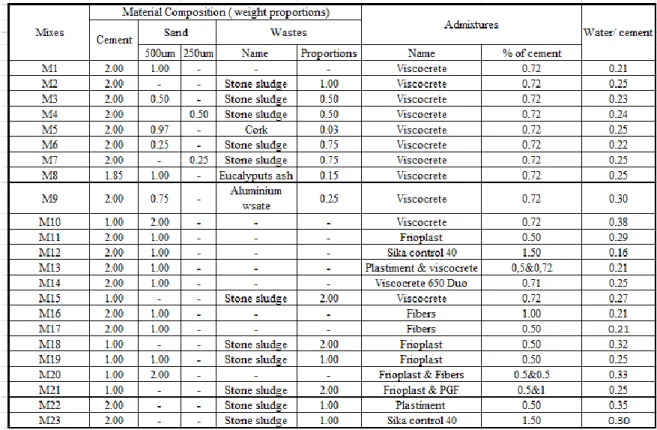
Several mixes were obtained from the past bibliographies and work done by others on this method and finally few mixes with wastes and admixtures were planned to incorporate in this work.
The reference [9] enlightens that 1:2 of cement : sand was used in 3D printing by companies, universities and individuals, but initially twin extruder was not able to extrude the mix, so we tried mix of 2:1 of cement : sand and it was possible to extrude, hence this mix was taken as reference mix. In order to obtain various compositions the reference mix was varied. Stone sludge was included as waste and in certain mixes sand was replaced by stone sludge by 50% and 100% along with the addition of superplasticizer. Eucalyptus ash was used as replacer for cement up to 15%, the cork was used as a replacer to the sand up to 3% and aluminium polishing waste was used as replacer for 25% in the mix.
![Table 2.1: Mix proportion [44].](https://thumb-eu.123doks.com/thumbv2/123dok_br/18556233.906341/37.892.245.669.815.914/table-mix-proportion.webp)
![Figure 2.2: Particle size distribution [9].](https://thumb-eu.123doks.com/thumbv2/123dok_br/18556233.906341/38.892.251.629.253.575/figure-particle-size-distribution.webp)
![Table 2.3: Mix design of 3D printable geo polymer mortar [49].](https://thumb-eu.123doks.com/thumbv2/123dok_br/18556233.906341/41.892.294.620.139.465/table-mix-design-of-printable-geo-polymer-mortar.webp)