Braz. J. of Develop.,Curitiba, v. 6, n. 8, p.58335-58348 aug. 2020. ISSN 2525-8761
An assessment of different turbulence models on a cfd simulation of air flow
past a s814 airfoil
Uma avaliação de diferentes modelos de turbulência numa simulação cfd de
fluxo de ar passando por um aerofólio s814
DOI:10.34117/bjdv6n8-299
Recebimento dos originais: 18/07/2020 Aceitação para publicação: 18/08/2020
Eduardo Corte Real Fernandes
Federal Univesity of Pernambuco, Department of Mechanical Engineering, Prof. Moraes Rêgo Endereço: Av., 1235 - Cidade Universitária, Recife - PE - Brazil - Zip Code: 50670-901 - Phone:
+55 81 2126-8000.
E-mail: eduardocrfernandes@gmail.com
Allan Cavalcante Belo
Federal Univesity of Pernambuco, Department of Mechanical Engineering, Prof. Moraes Rêgo Av., 1235 - Cidade Universitária, Recife - PE - Brazil - Zip Code: 50670-901 - Phone: +55 81
2126-8000.
Alex Maurício Araújo
Federal Univesity of Pernambuco, Department of Mechanical Engineering, Prof. Moraes Rêgo Endereço: Av., 1235 - Cidade Universitária, Recife - PE - Brazil - Zip Code: 50670-901 - Phone:
+55 81 2126-8000. .br
E-mail: ama@ufpe.br
Augusto Antônio Coutinho da Silva
Federal Univesity of Pernambuco, Department of Mechanical Engineering, Prof. Moraes Rêgo Endereço: Av., 1235 - Cidade Universitária, Recife - PE - Brazil - Zip Code: 50670-901 - Phone:
+55 81 2126-8000.
E-mail: augustocoutinho@gmail.com
Ciro Cordeiro de Araújo Bezerra
Federal Univesity of Pernambuco, Department of Mechanical Engineering, Prof. Moraes Rêgo Endereço: Av., 1235 - Cidade Universitária, Recife - PE - Brazil - Zip Code: 50670-901 - Phone:
+55 81 2126-8000.
: 50670-901 - Phone: +55 81 2126-8000. E-mail: ciro.cordeiro1@gmail.com
Guilherme José de Arruda Moura Rocha
Federal Univesity of Pernambuco, Department of Mechanical Engineering, Prof. Moraes Rêgo Endereço: Av., 1235 - Cidade Universitária, Recife - PE - Brazil - Zip Code: 50670-901 - Phone:
+55 81 2126-8000.
Braz. J. of Develop.,Curitiba, v. 6, n. 8, p.58335-58348 aug. 2020. ISSN 2525-8761
ABSTRACT
Turbulence modeling is a crucial part of any CFD simulation, the selection of an appropriate method allows for precise validation and reliable results. This paper aims to investigate which turbulence model is best suitable for a simulation over a S814 airfoil profile at different angles of attack using CFD software ANSYS-Fluent. Literature usually recommends two models for this kind of simulation: κ – ω Shear Stress Transport and Spalart-Allmaras. Both models strength and weakness are tested by performing simulations at the angles of attack: 0º, 5º, 10º, 15º, and 20º. Results were validated with experiments reported in literature and showed that Spalart-Allmaras performed better for lower angles of attack, whereas κ – ω Shear Stress Transport presented the best results at the higher angles of attack.
Keywords: CFD, Turbulence Modeling, ANSYS, Spalart-Allmaras, κ – ω SST. RESUMO
A modelação da turbulência é uma parte crucial de qualquer simulação de CFD, a selecção de um método apropriado permite uma validação precisa e resultados fiáveis. Este artigo visa investigar qual o modelo de turbulência mais adequado para uma simulação sobre um perfil de aerofólio S814 em diferentes ângulos de ataque, utilizando o software de CFD ANSYS-Fluent. A literatura recomenda geralmente dois modelos para este tipo de simulação: κ - ω Shear Stress Transport e Spalart-Allmaras. Tanto a força como a fraqueza dos modelos são testadas através da realização de simulações nos ângulos de ataque: 0º, 5º, 10º, 15º, e 20º. Os resultados foram validados com experiências relatadas na literatura e mostraram que Spalart-Allmaras teve um melhor desempenho nos ângulos de ataque mais baixos, enquanto que κ - ω O Transporte de Stress de Cisalhamento apresentou os melhores resultados nos ângulos de ataque mais altos.
Braz. J. of Develop.,Curitiba, v. 6, n. 8, p.58335-58348 aug. 2020. ISSN 2525-8761
1 INTRODUCTION
Aerodynamic analysis on profiles such as wings or blades of wind turbines can be done by studying a section of these components, called an airfoil, where forces are developed on the body by the distribution of pressure and shear stresses. This, originating from the non-slip condition, develops only in a thin layer close to the surface of the body, called the boundary layer (Netto et al, 2019).
Computational Fluid Dynamics (CFD) simulations have been applied to diverse fields of engineering, including wind energy. These simulations can determine the aerodynamic behaviour of different types of turbines in order to select parameters so as to optimize its efficiency. Hence, the use of CFD software is a powerful tool to assist the design process of a real wind turbine (Hernández Gómez, 2014).The boundary conditions, and turbulence model are some of the parameters that influence CFD modeling. The present paper deals the influence of these parameters. Because of the chaotic and random nature of a turbulent flow possibility of a precise description of the movement of all fluid particles is impossible, nevertheless the flow can be decomposided by a mean value, with positive and negative fluctuations (Versteeg and Malalasekera, 2007). Consequently, more equations are added to the problem, reinforcing the importance of CFD, because otherwise it would not be possible to solve the case.
Carrying on the studies of De Magalhães Melo et al (2013), which develops a method for a CFD simulation over a S814 airfoil profile demonstrating that good simulation practices should bring consistent results, the present paper aims to apply this method to investigate which turbulence model is best suitable for this simulation at different wind conditions.
A similar study was conducted by Eleni et al (2012) on a NACA 0012 profile, using the following turbulence models: Spalart-Allmaras, Realizable κ - ε and κ – ω Shear Stress Transport (SST), with the latter presenting the best results. Rocha et al (2014) performed a calibration study of the κ – ω SST turbulence model for small scale wind turbines simulating on both NACA 0012 and NACA 4412 profiles. In general, according to Wang and Xiongwei, (2016), κ – ω SST model is considered to be the most successful for both 2D and 3D airfoils CFD modeling, despite the representation of roughness in such model not being entirely consistent or straightforward (Franke
et al, 2004).
On the other hand, the Spalart-Allmaras is also widely used on this type of simulation. Fernandes et al (2010) performed a study in a NACA 2410 airfoil comparing κ - ε, κ – ω SST and Spalart-Allmaras using the opensource CFD software Openfoam finding the latter to be the most successful. A CFD simulation of air flowing past a fixed 2D NACA 0015 airfoil using the Spalart–
Braz. J. of Develop.,Curitiba, v. 6, n. 8, p.58335-58348 aug. 2020. ISSN 2525-8761
Allmaras turbulence model combined with a Navier–Stokes solver based on a Chorin projection method was performed by Nordanger et al (2015). Likewise, a study developed by Pellerin et al (2015) shows that Spalart–Allmaras leads to results that successfully capture the experimental lift and drag patterns reported in the literature for S1223 and E387 airfoils.
Song and Perot (2014) showed that for inlet speeds below the machine stall, turbulence models present results consistent with the literature. However, when approaching the stall, great differences are perceived during the simulations due to the limitations of these models. This is reflected in the calculated values of pressure along the airfoil string, as well as in the torque of the low speed shaft.
The present study will run simulations of a flow over a S814 airfoil profiles at different AoA using the κ – ω SST and Spalart-Allmaras to determine which one is best considering criteria such as results accuracy and computational cost. Experimental results as Jonkman (2014) and Janiszewska et al (1996) are used to validate the simulations.
2 METHODOLOGY
In order to determine which one is the best turbulence model, steady state CFD simulations of a flow over an S814 airfoil will be tested at different angles of attack and at Reynolds number of approximately 6
1.5 10 . Geometry and mesh are created with the ANSYS Workbench together with ANSYS Fluent. Results will be compared to Jonkman (2014) and Janiszewska et al (1996) to analyse which model best describes the problem.
2.1 COMPUTATIONAL DOMAIN
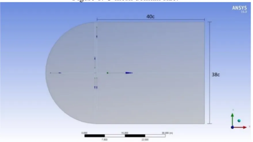
Two types of domain are commonly used in this type of problem: O-Mesh and C-mesh domains. In the O-Mesh domain a circle surrounds the airfoil, whereas in the C-mesh domain, a semi-circle coupled with a rectangle is used. The latter allow for better representation of the airfoil wake and, therefore was chosen (Ribeiro et al, 2011 and De Magalhães Melo et al, 2013)
The domain must be large enough, so that wall effects will not significantly influence the flow field (Liu et al, 2016). Due to this fact, the computational domain was dimensioned with approximately 19c x 40c in which “c” is the chord length (De Magalhães Melo et al, 2013). The domain is shown in figure 1.
Braz. J. of Develop.,Curitiba, v. 6, n. 8, p.58335-58348 aug. 2020. ISSN 2525-8761 Figure 1: C-mesh domain size.
2.2 BOUNDARY CONDITIONS
Boundary conditions are shown in figure 2. The upper and lower surfaces are treated as non-slip wall, which imposes tangential velocity to be zero near the wall (Çengel and Cimbala, 2015).
Figure 2: Boundary Conditions used for the software ANSYS Fluent.
Inlet velocity was determined so that the Reynolds would be approximately 6 1.5 10 . This value was chosen according to Janiszewska et al (1996). Using the chord length of 1m and a kinematic viscosity of air 5
1.562 10 − m²/s, a value of inlet speed of 23.43 m/s was calculated. Furthermore, the outlet region was set to atmospheric pressure.
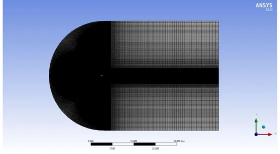
2.3 WAKE REFINEMENT
Turbulence models give two important characteristics of wind turbine wake: 1) the velocity deficit directly associated with the loss of power in large wind farms and 2) dynamic load on the turbine (Wu and Porté-Agel, 2012). Thus, a mesh refinement on the wake region is necessary in order to better analyse these factors, as shown in figure 3:
Braz. J. of Develop.,Curitiba, v. 6, n. 8, p.58335-58348 aug. 2020. ISSN 2525-8761
Figure 3: Refinement in the semicircle and, after the trailing edge, refinement until the end of the computational domain.
2.4 MESH CREATION
Another important refinement region is the airfoil itself. Refinement techniques were used around it as shown in figure 4, allowing for better visualization of the boundary layer detachment region and vortices formation. In this simulation, 540000 elements were obtained from 541800 nodes.
Figure 4: Refinement techniques near the S814 airfoil.
2.5 TURBULENCE MODELS
Current turbulence models can be grouped into three main categories: Reynolds-Averaged Navier-Stokes (RANS), Large Eddy Simulation (LES) and Direct Numerical Simulation (DNS). The last two are highly costly in terms of computing resources and will not be addressed in this
Braz. J. of Develop.,Curitiba, v. 6, n. 8, p.58335-58348 aug. 2020. ISSN 2525-8761
paper (Versteeg and Malalasekera, 2007 and Smyth, 2016). Both Spalart-Allmaras and κ – ω SST are classified as RANS models. In these models, velocity and pressure are broken into mean and fluctuating components, which are substituted into the original Navier-Stokes equation, reducing computational costs significantly (Smyth, 2016).
2.5.1 Sparlat-Allmaras
The Spalart-Allmaras model is a one-equation model that solves a modelled transport equation for kinematic eddy (turbulent) viscosity parameter ~ , (ANSYS, 2013). This model was designed specifically for aerospace applications involving wall-bounded flows and has been shown to give good results for turbulence boundary layers subjected to adverse pressure gradients. The (dynamic) eddy viscosity is related to ~ by:
t =~ fv1 (1)
Equation 1 has a wall damping function, given by:
3 1 3 3 1 v v f C = + (2) Where: ~ v = (3)
Generally, ~ is equals except in the viscous region (Sparlat and Allmaras, 1992). For high Reynolds numbers, fv1 tends to one, whereas in the wall region, it tends to zero (Versteeg and Malalasekera, 2007).
For the Fluent Solver, the input data chosen was the ratio of the turbulent viscosities t
,
Braz. J. of Develop.,Curitiba, v. 6, n. 8, p.58335-58348 aug. 2020. ISSN 2525-8761 2.5.2 κ – ω SST
The Shear-Stress Transport (SST) model was developed by Menter et al (2003), to combine the precise and robust formulation of the κ – ω model in the near-wall region as well as maintaining free-flow in a far distant region. The model assumes a transition region between the regions of close to the wall and far regions. It uses a blending function to combine these two regions.
The input data was used in the Fluent Solver. The turbulent kinetic energy, κ, and ω (the rate at which the turbulent kinetic energy is converted to thermal energy) were calculated (Versteeg and Malalasekera, 2007):
= (4)
The turbulent kinetic energy is calculated:
(
)
22 3 Uref Ti
=
whereas omega is expressed by:
(5)
3/ 2
l
= (6)
The value found for was 0.9149 m²/s², where Uref is the reference velocity (velocity inlet)
and Ti is the turbulence intensity. In this article, Uref was optained 23.43 m/s and Tii was 5%. The
“l” is equivalent to 0.07L, where L is the characteristic length of the experiment, which, for the case of this study, is the chord length, which is 1 meter (Versteeg and Malalasekera, 2007). Therefore, a value for ε of 125.0236 m²/s³ and ω of 136.6465 1
s− were obtained.
2.6 SIMULATION
Final results with both models were obtained and compared to Jonkman (2014) and Janiszewska et al (1996), for the S814 airfoil. The most suitable for each situation was determined considering convergence, precision and computational cost criteria.
Braz. J. of Develop.,Curitiba, v. 6, n. 8, p.58335-58348 aug. 2020. ISSN 2525-8761
3 RESULTS AND DISCUSSION
Utilizing a chord length of 1 m, Reynolds number of approximately 6
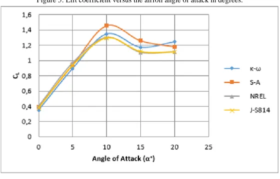
1.5 10 and experimental data provided by Jonkman (2014) and Janiszewska et al (1996), the results for the S814 airfoil showed that the S-A turbulence model works best at lower AoA, up to 10°. However, κ – ω SST model performs better at higher AoA, except for 20º where S-A presented a lower error. Figure 5 shows the variation of the lift coefficient versus the angle of attack of the airfoil.
The best performance at lower values AoA can be explained by the fact that the S-A model solves the whole flow field for a refined mesh (ANSYS, 2013).
Figure 5: Lift coefficient versus the airfoil angle of attack in degrees.
At higher angles of attack, the airflow detaches faster from the airfoil, requiring a more refined model for turbulent regions such as the κ – ω SST model. This model combines the optimal performance of the κ – ω model for wall-limited and low-Reynolds numbers using wall functions, with the κ - ε model for the fully turbulent regions.
The results agree with Hao et al (2014) and Versteeg and Malalasekera (2007). For turbulent regions with a high density of vortices, S-A does not bring satisfying results. However, κ – ω SST performs well at these regions, and thus brings better results at higher AoA.
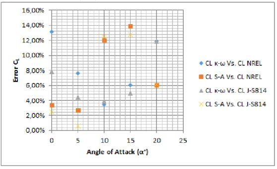
The error compared to Jonkman (2014) and Janiszewska et al (1996) is shown in figure 6. The highest error was observed (around 14%) when the lift coefficient calculated by the S-A model was compared to NREL data. These errors values do not represent a very large discrepancy and therefore the model was validated.
Braz. J. of Develop.,Curitiba, v. 6, n. 8, p.58335-58348 aug. 2020. ISSN 2525-8761
Figure 6: Relative errors of the lift coefficients for several models of turbulence versus angle of attack compared to Jonkman (2014) and Janiszewska et al (1996).
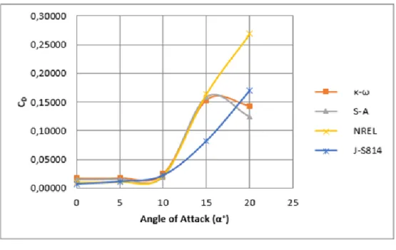
The drag coefficient was also studied and analysed. As expected from the work of Fernandes (2010), this coefficient can be super or underestimated at times. This is because RANS turbulence models assume that the whole flow is turbulent on the profile, which is not in accordance with reality, since there is usually a significant extension over the airfoil where the regime can be laminar or transition, leading to errors.
In addition, Bordin (2014) and Anderson Junior (2015) state that all real airfoils of finite extension possess less lift and drag than data from their airfoil sections indicate. The pressure difference between upper and lower blade surfaces causes a flow to occur at its extremity, generating a vortices trail, which decreases pressure difference and, consequently, the lift force. The effective angle of attack decreases with the downward velocities induced by vortices, causing lift to have a component in the flow direction, kwon as induced drag.
According to Wilcox (2006), based on the approach of Boussinesq, there is an increase of turbulent friction on the profile, even in zones where the regime is laminar. Therefore, it can be concluded from this theory that there is an error for the drag coefficient inherent to any model of turbulence chosen as also shown in SONG and PEROT (2014). Nevertheless, the present work showed significantly lower errors when compared to that of Fernandes (2010).
Figures 7 and 8 show the behaviour of the drag coefficient for various angles of attack and the respective errors compared to the data of Jonkman (2014) and Janiszewska et al (1996).
Braz. J. of Develop.,Curitiba, v. 6, n. 8, p.58335-58348 aug. 2020. ISSN 2525-8761 Figure 7: Drag coefficient versus the airfoil angle of attack in degrees.
Figure 8: Relative errors of the drag coefficients for several models of turbulence versus angle of attack compared to Jonkman (2014) and Janiszewska et al (1996).
4 CONCLUSION
According to the presented simulations on steady state, with each angle of attack simulated separately, it was observed that for lower AoA the S-A presents a lower error of lift coefficient compared to the experimental data; however, as AoA increases, this model's accuracy decreases. In contrast, for higher AoA κ – ω SST presents best results when compared to Jonkman (2014) and Janiszewska et al (1996). As for the drag coefficient, the error is intrinsic to the turbulence model because there are regions where the flow can be laminar or transition, leading the model to failure.
Braz. J. of Develop.,Curitiba, v. 6, n. 8, p.58335-58348 aug. 2020. ISSN 2525-8761
Thus, when pursuing good engineering practices, and in a certain way computational economy, in steady state simulations of a flow over a S814 airfoil S-A or κ – ω SST can be used depending on the AoA.
ACKNOWLEDGEMENTS
The authors would like to acknowledge the Graduate Program in Mechanical Engineering at the Federal University of Pernambuco (PPGEM/UFPE) and the Ministry of Education of Brazil through CAPES and CNPq for supporting this work. We thank ANSYS for providing the ANSYS Fluent student version, which have been used in this study. In addition, we are grateful to the help of all colleagues involved in this work.
RESPONSIBILITY NOTICE
Braz. J. of Develop.,Curitiba, v. 6, n. 8, p.58335-58348 aug. 2020. ISSN 2525-8761
REFERENCES
Anderson Jr, John D. Fundamentos de Engenharia Aeronáutica. AMGH Editora, 2015.
ANSYS® Academic Research, Release 15.0, Help System, “ANSYS Fluent Theory Guide”, 2013. Bordin, Franciele Stail. "Análise do efeito da interação fluido-estrutura nas forças fluidodinâmicas em um elemento de pá flexível 3D." (2014).
Cengel, Yunus A., and John M. Cimbala. Mecânica dos fluidos-3. AMGH Editora, 2015.
De Magalhães Melo, G. G..; Oliveira, L. A.; Araújo, A. M.; Asibor, A. I.; De Medeiros, A. L. R.; De Oliveira Filho, O. D. Q.; Espíndola, R. L.; Machado, H. C. M.; Jaouen, P.; Noguerra, R. E. “Application of good CFD simulation practices to s814 airfoil profile". In: International Congress of Mechanical Engineering, 22, 2013, Ribeirão Preto. Anais… Ribeirão Preto, 2013, p 3980 – 3989.
Eleni, Douvi C., Tsavalos I. Athanasios, and Margaris P. Dionissios. "Evaluation of the turbulence models for the simulation of the flow over a National Advisory Committee for Aeronautics (NACA) 0012 airfoil." Journal of Mechanical Engineering Research4.3 (2012): 100-111.
Fernandes, M. P. G.; Rocha, P. A. C.; Carneiro, F. O. M. “Avaliação de resultados de simulação numérica de escoamento sobre o perfil NACA 2410 utilizando o openfoam com diferentes modelos de turbulência”. In: Congresso Nacional de Engenharia Mecânica, 2010, Campina Grande. Anais… Campina Grande, 2010, 9p.
Franke, J.; Hirsch, C.; Jensen, A. G.; Krüs, H. W.; Schatzmann, M.; Westbury, P. S.; Wisse, J. A.; Wright, N. G. “Recommendations on the use of CFD in wind engineering." Cost action C. Vol. 14. 2004.
Hao. Y.; Liu, Yangwei.; Le, F.; Lipeng, L. "Modification of Spalart-Allmaras turbulence model for predicting S825 airfoil aerodynamic performance." Applied Mechanics and Materials. Vol. 543. Trans Tech Publications, 2014.
Hernández Gómez, Antonio. “Computational Fluid Dynamics study of 2D vertical axis turbines for application to wind and tidal energy production”. BS thesis. Universitat Politècnica de Catalunya, 2014.
Janiszewska, J. M.; Ramsay, R. R.; Hoffmann, M. J.; Gregorek, G. M. 1996. Effects of grit roughness and pitch oscillations on the S814 airfoil. No. NREL/TP--442-8161. National Renewable Energy Lab., Golden, CO (United States).
Jonkman, J., and Marshall L. Buhl Jr. "NWTC information portal (FAST)." 2015-05-15].
https://nwtc. nrel. gov/FAST (2014).
Liu, Z.; Takeshi, I.; He, X.; Niu, H. "Les study on the turbulent flow fields over complex terrain covered by vegetation canopy." Journal of Wind Engineering and Industrial Aerodynamics 155 (2016): 60-73.
Braz. J. of Develop.,Curitiba, v. 6, n. 8, p.58335-58348 aug. 2020. ISSN 2525-8761
Menter, F. R., M. Kuntz, and R. Langtry. "Ten years of industrial experience with the SST turbulence model." Turbulence, heat and mass transfer 4.1 (2003): 625-632.
Netto, D. C.; Camacho, R. G. R.; Souza, D. S. Estudo Comparativo de metodologias para solução numérica da camada-limite turbulenta sobre o aerofólio nrel s809. Brazilian Journal of
Development v. 5, n. 9, p. 16180-16198.fe 2019
Nordanger, Knut.; Holdahl, R.; Kvamsdal, T.; Kvarving, A. M.; Rasheed, A. "Simulation of airflow past a 2D NACA0015 airfoil using an isogeometric incompressible Navier–Stokes solver with the Spalart–Allmaras turbulence model." Computer Methods in Applied Mechanics and Engineering 290.
Pellerin, N.; Leclaire, S; Reggio, M. "An implementation of the Spalart–Allmaras turbulence model in a multi-domain lattice Boltzmann method for solving turbulent airfoil flows." Computers & Mathematics with Applications 70.12 (2015): 3001-3018.
Ribeiro, A.F.P., Awruch A.M., Gomes, H.M. 2011. "An airfoil optimization technique for wind turbines." Applied Mathematical Modeling 36.10 (2012): 4898-4907.
Rocha, PA Costa.; Rocha, H. H. B.; Carneiro, F. O. M.; Bueno, A. V. "k–ω SST (shear stress transport) turbulence model calibration: A case study on a small scale horizontal axis wind turbine." Energy 65 (2014): 412-418.
Smyth, Thomas AG. "A review of Computational Fluid Dynamics (CFD) airflow modeling over aeolian landforms." Aeolian Research 22 (2016): 153-164.
Spalart, P. and Allmaras, S. A. (1992). "A one equation turbulence model for aerodynamic flows." RECHERCHE AEROSPATIALE-FRENCH EDITION- (1994): 5-5.
Versteeg, H. K.; Malalasekera. An introduction to computational fluid dynamics: the finite volume method. Pearson Education, 2007.
Wang, Lin.; Liu, Xiongwei.; Kolios, Athanasios. "State of the art in the aeroelasticity of wind turbine blades: Aeroelastic modeling." Renewable and Sustainable Energy Reviews 64 (2016): 195-210.
Wilcox, D. C. Turbulence Modeling for CFD. Third Edition. La Canãda, California: DCW Industry, 2006. 522 p.
Wu, Y. T.; Porté-Agel, F. (2012). "Atmospheric turbulence effects on wind-turbine wakes: An LES study." Energies 5.12 (2012): 5340-5362.