Gonçalo Miguel Rodrigues de Brito Barros
Licenciado em Ciências da Engenharia Electrotécnicae de Computadores
Serviços Pós-4G em Redes de Satélite LEO
com Recepção Multi-Pacote e com Handover
Dissertação para obtenção do Grau de Mestre em Engenharia Electrotécnica e de Computadores
Orientadores :
Luís Bernardo, Professor Auxiliar, FCT-UNL
Rui Dinis, Professor Auxiliar com Agregação,
FCT-UNL
Júri:
Presidente: Prof. Paulo Montezuma
Arguente: Prof. António Rodrigues
iii
Serviços Pós-4G em Redes de Satélite LEO com Recepção Multi-Pacote e com Handover
Copyright c Gonçalo Miguel Rodrigues de Brito Barros, Faculdade de Ciências e Tec-nologia, Universidade Nova de Lisboa
Acknowledgements
First of all i would like to thank to my supervisor Prof. Luís Bernardo for giving me the opportunity to realize this dissertation. His knowledge, availability and patience were extremely important during all the time i spent doing this work. I am also grateful to my co-supervisor Prof. Rui Dinis and to Prof. Paulo Montezuma, who were truly fundamen-tal in my dissertation development.
I am very thankful to UNINOVA for giving me the chance to participate in the project MPSAT PTDC/EEATEL/099074/2008, and for providing me a research grant during four months.
It would not be possible for me to reach this stage without my course colleagues. I am specially grateful to João Melo, Francisco Esteves, Gonçalo Alves, Nuno Vasconcelos, An-tónio Furtado, João Rodrigues and Gonçalo Carvalho, for their friendship, and for all the time they spent helping me when i needed.
I am totally blessed for having Ana Roque as my girlfriend. She was always by my side during all the course, and beyond the love and the friendship, she always believed in my capabilities and in my will to succeed.
I’m very lucky to have amazing friends outside the faculty. I would like to thank specially to Pedro Amaro, Paulo Borges, Tiago Nascimento, Isaque Tito, Mauro Alves and David Gaspar, for all the moments of joy, and for the proofs of real friendship that you daily show to me since we were little boys. I could not write my acknowledgements without mentioning my big friend Emanuel Neto, that will not read this, but his advices and all the things that he taught me, will always be present in my life.
Abstract
Traditionally, a packet with errors, either due to channel noise or collisions, is discarded and needs to be retransmitted, leading to performance losses. Hybrid Automatic Retrans-mission reQuest (H-ARQ) and time diversity multipacket reception approaches, such as Network Diversity Multiple Access (NDMA), improve the system performance by requesting additional retransmissions and combining all the signals received together. However, the high round trip delay time associated to satellite networks introduces lim-itations in the number of retransmission requests that may be issued by the terminals to fulfil the Quality of Service (QoS) requirements.
This thesis considers the design of hybrid protocols combining H-ARQ and NDMA for satellite networks with demand-assigned traffic. The satellite NDMA (S-NDMA) proto-col is presented and analytical models are proposed for its performance. Energy efficient QoS provisioning is also analysed. The proposed system’s performance is evaluated for a Low Earth Orbit (LEO) network with a Single-Carrier with Frequency Domain Equal-ization (SC-FDE) scheme, and compared to H-NDMA. Results show that the proposed system is energy efficient and can provide enough QoS to support high demand services such as video telephony.
Several satellites are needed to cover a broad area of the planet. As the satellites are constantly moving, their footprints are permanently changing positions. This leads to a need for a handheld mobile terminal to change its communication to another satellite. Two handover schemes are proposed on this thesis for S-NDMA protocol: the conven-tional cold handover and an hot handover based on a distributed Single-Input Multiple-Output (SIMO) approach. Their feasibility and performance are compared, taking into account the energy efficiency, the Doppler deviation, the optimal handover point and time offset.
Keywords: S-NDMA, H-NDMA, SC-FDE, Satellites, Doppler deviation, Quality of
Resumo
Um pacote com erros, quer seja devido à existência de colisões ou ruído no canal, é nor-malmente descartado e necessita de ser retransmitido, levando a perdas de desempenho. A junção do protocolo H-ARQ (Hybrid Automatic Retransmission reQuest) com técni-cas de recepção multi-pacote e com diversidade temporal como o NDMA (Network Di-versity Multiple Access), melhoram o desempenho, visto terem a capacidade de pedir transmissões extra e combinar todos os sinais recebidos no mesmo período. Contudo, o atraso provocado pelo tempo de ida e volta na comunicação com uma rede de satélites, limita o número de retransmissões que possam ser pedidas pelos terminais para garantir qualidade de serviço.
Esta tese considera o desenho de um protocolo híbrido que combina H-ARQ com NDMA para redes satélites com tráfego atribuído a pedido. O protocolo S-NDMA (Satellite NDMA) é apresentado, juntamente com modelos analíticos para o seu desempenho. É analisada a sua eficiência energética, tendo em conta requisitos de qualidade de serviço (QoS). O sistema é feito para satélites de órbita baixa (LEO) e com SC-FDE (Single-Carrier with Frequency Domain Equalization). É feita também uma comparação de desempe-nhos deste esquema com H-NDMA (Hybrid-NDMA), mostrando que é eficiente em ter-mos energéticos e que cumpre requisitos de QoS para serviços exigentes como videocha-madas.
xii
Palavras-chave: S-NDMA, H-NDMA, SC-FDE, Satélites, Doppler deviation, Qualidade
Contents
1 Introduction 1
1.1 Motivation . . . 1
1.2 Objectives and Contributions . . . 2
1.3 Dissertation structure . . . 3
2 Literature Review 5 2.1 Satellite Constellations . . . 5
2.2 Satellite System Architecture . . . 6
2.3 Iridium Satellite System . . . 6
2.4 LEO Frequency Range . . . 7
2.5 Multiple Access Techniques and Channel Achievement . . . 8
2.5.1 TDMA . . . 8
2.5.2 FDMA . . . 8
2.5.3 Orthogonal Frequency Division Multiplexing . . . 9
2.5.4 Single Carrier with Frequency Division Equalizer . . . 9
2.5.5 CDMA . . . 10
2.6 ARQ schemes . . . 10
2.7 Forward Error Correction schemes . . . 12
2.8 Hybrid ARQ Schemes . . . 13
2.8.1 Type I Hybrid-ARQ . . . 13
2.8.2 Type II Hybrid-ARQ . . . 14
2.9 Multiple-Input Multiple-Output (MIMO) systems . . . 14
2.10 MAC Protocols in satellite communications . . . 15
2.10.1 Random Access Protocols . . . 16
2.10.2 Demand Assigned Multiple Access . . . 16
2.10.3 Reservation Protocols . . . 17
2.10.4 Hybrid of Random Access and Reservation Protocols . . . 17
xiv CONTENTS
2.11.1 Multiple Packet Reception . . . 18
2.12 PHY-MAC Cross-layered Designs . . . 19
2.12.1 Network Diversity Multiple Access . . . 20
2.12.2 Hybrid NDMA . . . 21
2.13 Handover in Satellite Systems . . . 22
2.13.1 Spot-beam Handover Schemes . . . 23
2.13.2 Satellite Handover Schemes . . . 23
2.13.3 ISL Handover Schemes . . . 24
3 Satellite Communications 25 3.1 System Characterization . . . 25
3.2 Medium Access Control Protocol . . . 26
3.2.1 Handling very low power using CDMA . . . 28
3.2.2 Multipacket Detection Receiver Structure . . . 28
3.3 Analytical Model . . . 30
3.3.1 Packet Transmission . . . 30
3.3.2 Transmission Parameters . . . 33
3.3.3 Throughput . . . 34
3.3.4 Packet Service Time . . . 34
3.3.5 Energy Consumption . . . 35
3.3.6 QoS Constraints . . . 36
3.4 Performance Analysis . . . 37
4 Satellite Handover 45 4.1 Communication with Two Satellites . . . 45
4.1.1 Multipacket Detection Receiver Structure . . . 46
4.1.2 Packet Transmission for Two Satellites . . . 47
4.2 Intra-planar Handover Scheme . . . 47
4.3 Iridium Handover Scheme . . . 49
4.4 Intra-planar Handover Scheme Performance Analysis . . . 51
4.4.1 Doppler Deviation . . . 51
4.4.2 Time Offset . . . 52
4.4.3 Throughput Analysis . . . 54
4.4.4 Energy Consumption Analysis . . . 55
4.4.5 Packet Delay Analysis . . . 55
4.5 Iridium Handover Scheme Performance Analysis . . . 56
4.5.1 Doppler Deviation . . . 56
4.5.2 Time Offset . . . 57
4.5.3 Throughput Analysis . . . 58
4.5.4 Energy Consumption Analysis . . . 59
CONTENTS xv
List of Figures
2.1 OFDM and SC-FDE — signal processing [FABSE02] . . . 10
2.2 Spectral-efficiency bound as a function of noise-spectral-density-normalized energy per information bit Eb N0 [BFC05] . . . 15
2.3 Satellite handover: a) initially, user 1 and user 2 communicate through satellite A and B; and b) after user 2 hands over to satellite C, the commu-nication is through satellites A, B, and C. Figure from [CAI06a]. . . 24
3.1 S-NDMA Demand Assigned scheme . . . 27
3.2 Mapping to physical layer matrix example . . . 27
3.3 Satellite withθdisplacement for RTT calculation purposes . . . 37
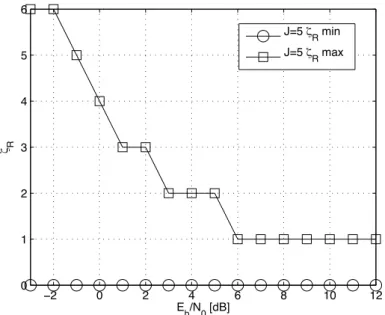
3.4 ζRmaximum (satisfyingP ERmax) and minimum (satisfyingP ER≤99%) overEb/N0forP = 5MTs. . . 39
3.5 (EP U P/Ep)(Eb/N0)for varyingnovern1 forEb/N0 = −2dB and P = 5 MTs. . . 39
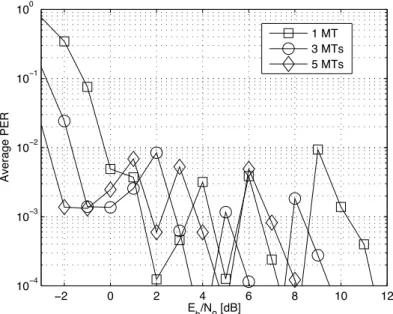
3.6 Average PER overEb/N0andP for S-NDMA and H-NDMA. . . 40
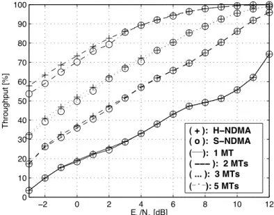
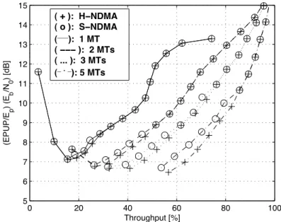
3.7 Saturated throughput overEb/N0forP = 5MTs for S-NDMA and H-NDMA. 41 3.8 (EP U P/Ep)(Eb/N0)overEb/N0andPfor S-NDMA and H-NDMA. . . . 41
3.9 (EP U P/Ep)(Eb/N0)over Throughput (S) andPfor S-NDMA and H-NDMA. 42 3.10 Eb/N0over Throughput (S) andP for S-NDMA and H-NDMA. . . 42
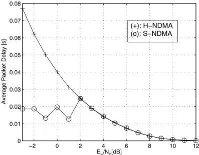
3.11 Average packet delay overEb/N0forP = 5MTs. . . 43
4.1 Basics of the communication with two satellites . . . 45
4.2 Intra-planar Handover Scheme . . . 48
4.3 Maximum satellite range . . . 48
4.4 CDMA Frame . . . 49
4.5 Iridium Handover Scheme . . . 50
4.6 Doppler Deviation . . . 51
4.7 Doppler Deviation(α) . . . 52
xviii LIST OF FIGURES
4.9 Throughput(α) . . . 54
4.10 EPUP(α) . . . 55
4.11 Packet Delay(α) . . . 56
4.12 Doppler Deviation for Iridium Handover Scheme(x) . . . 57
4.13 Propagation Delay (x) . . . 58
4.14 Throughput (x) . . . 59
4.15 EPUP (x) . . . 60
Acronyms List
3GPP 3rd Generation Partnership Project
ACK Acknowledgement
ARQ Automatic Repeat Request
AWGN Additive White Gaussian Noise
BER Bit Error Rate
BS Base Station
CDMA Code Division Multiple Access
CP Cyclic Prefix
CSMA/CD Carrier Sense Multiple Access with Collision Detection
CSMA Carrier Sense Multiple Access
DAMA Demand Assigned Multiple Access
EFC Earth Fixed Cell
FDE Frequency Domain Equalization
FDM Frequency Division Multiplexing
FDMA Frequency Division Multiple Access
FEC Forward Error Correction
FFT Fast Fourier Transform
FIFO First-In First-Out
xx ACRONYMS LIST
GSM Global System for Mobile Communications
GSO Geostationary Orbit
H-ARQ Hybrid-Automatic Repeat Request
H-MAC Hybrid-Medium Access Control
H-NDMA Hybrid-ARQ NDMA
IC Interference Cancellation
IFFT Inverse Fast Fourier Transform
IP Internet Protocol
ISI Intersymbol Interference
ISL Inter Satellite Link
KMA Known Modulus Algorithms
LDPC Low Density Parity Check
LEO Low Earth Orbit
LTE Long Term Evolution
MAC Medium Access Control
MEO Medium Earth Orbit
MIMO Multiple-Input Multiple-Output
MMSE Minimum Mean Square Error
MPR Multiple Packet Reception
MUD Multi-User Detection
MT Mobile Terminal
M-QAM Multi-Level Quadrature Amplitude Modulation
NACK Negative Acknowledgement
NDMA Network-assisted Diversity Multiple Access
NGSO Non-Geostationary Orbit
OFDM Orthogonal Frequency Division Multiplexing
xxi
PAPR Peak average power ratio
PER Packet error rate
PHY Physical
PIC Parallel Interference Cancellation
PSTN public switching telephone network
QoS Quality of Service
QPSK Quadrature Phase Shift Keying
RF Radio Frequency
RSSI Radio Signal Strength Indicator
RTT Round-Trip-Time
SC Single Carrier
SC-FDE Single Carrier - Frequency Domain Equalization
SFC Satellite Fixed Cell
SIC Successively Interference Cancellation
SISO Single-Input Single-Output
SIMO Single-Input Multiple-Output
SMS Short Message Service
S-NDMA Satellite-Network-assisted Diversity Multiple Access
SNR Signal-to-noise ratio
SR Selective Repeat
TC Turbo Codes
TDMA Time Division Multiple Access
UHF Ultra High Frequency
V-BLAST Vertical-Bell Laboratories Layered Space-Time
VHF Very High Frequency
VSAT Very-small-aperture terminal
1
Introduction
1.1
Motivation
The future of telecommunications aims to provide permanent and ubiquitous connectiv-ity, regardless of location. Satellite communication systems can lead telecommunications networks to a level where they provide global connectivity anywhere and any time; they make possible a reachability on inaccessible areas, or areas where terrestrial infrastruc-ture has been damaged. By having a global reach, with a flexible bandwidth-on-demand capability, these networks make possible the access to satellites channels from any earth station within satellite’s coverage area[CY99].
1. INTRODUCTION 1.2. Objectives and Contributions
1.2
Objectives and Contributions
A Low Earth Orbit (LEO) satellite network with a SC-FDE scheme is considered on this dissertation. The satellite network considered, is based inIridiumsatellite constellation [www10], so characteristics of this Motorola’s system are present throughout the disser-tation chapters. This research work took into account the recently proposed Hybrid-ARQ NDMA (H-NDMA) [GPB+11], which was created to enhance NDMA [TZB98] protocol’s error resilience capability. However, H-NDMA is unsuitable for satellite networks due to the multiple control packets required for additional retransmissions and acknowledge-ments, which may introduce delay and jitter incompatible with several kinds of QoS requirements [AMCV06]. So, in order to overlap those issues, a S-NDMA protocol is pro-posed in this dissertation.
S-NDMA adapts the design of H-NDMA principles to a Demand Assigned Multiple Ac-cess (DAMA) satellite scenario, adapting Hybrid-Automatic Repeat Request (H-ARQ) to work with a bounded number of acknowledgement packets. The first part of this con-tribution is present in chapter 3, where S-NDMA is presented and analytical models are proposed for obtaining the throughput, energy consumption and transmission delay of S-NDMA. In another relevant original contribution, this dissertation defines an optimiza-tion approach for S-NDMA to minimize the energy consumpoptimiza-tion satisfying a set of QoS requirements on a DAMA scenario, where the number of MTs (Mobile Terminals) trans-mitting is known a priori. Those QoS requirements were chosen to match the rigorous requirements of services like video streaming or video telephony applications. S-NDMA is compared with H-NDMA protocol on chapter 3, in order to clarify the performance differences between both protocols.
1. INTRODUCTION 1.3. Dissertation structure
1.3
Dissertation structure
2
Literature Review
2.1
Satellite Constellations
It is important to know about satellite constellations and subsequent orbit types before developing satellite networks.
There are two main known types of satellite constellations: Geostationary Orbit (GSO) and Non-Geostationary Orbit (NGSO)[CAI06a][BWZ00].
In the first case, satellites move circularly around the Earth in approximately twenty four hours, which means that they move synchronously with the planet movement. GSO con-stellation stands in equator plane at an altitude of 35786 Km. As the altitude for Earth’s surface is large, each satellite covers one third of the planet, so there is no need to have a large number of satellites to cover the entire Earth’s surface.
The big altitude in GSO constellations could have a counterpoint in terms of power con-sumption from MTs and propagation delay, which is too high for real time applications. Inmarsat satellite system is an example of a GSO constellation.
In Non-Geostationary constellations, the satellites movement is asynchronous in rela-tion to Earth’s movement. NGSO could be Low Earth Orbit (LEO) where satellites stand above the Earth’s surface at an altitude between 500 and 2000 km, or Medium Earth Or-bit (MEO), which have satellites at an altitude of 3000 to 4000 km. Both orOr-bits can be circular or elliptical. A disadvantage of NGSO in relation to GSO constellations is the lower Earth’s surface coverage due to the minor altitude where satellites are standing. However, an advantage of NGSO constellations over GSO constellations is the lower propagation delay, allowing the usage of real time applications.
2. LITERATUREREVIEW 2.2. Satellite System Architecture
2.2
Satellite System Architecture
Several parameters must be taken into account in the design of a LEO satellite constella-tion, including transmission delay, service coverage, minimum elevation angle and the effects of space radiation [SY07]. A satellite system can be presented as an access network or as a core network.
In the first case, the satellite retransmits the signal that is received from a terminal to a gateway on earth. This gateway transmits the signal to a terrestrial core network, where the transmission to further neighbours is proceeded.
Regarding the latter case, which is the access/core network, the satellite receives the sig-nal from the termisig-nal and passes it through Inter Satellite Link (ISL) (which are part of a satellite network), until the satellite that serves the destination terminal is reached. These Inter Satellite Link (ISL), can be established between satellites belonging to the same type of orbit, and a link-budget is provided for the link connected to the terminal. Initially, satellites worked as retransmission stations, so the regeneration of the signal was not im-plemented on them.
In the first satellite systems the retransmission between satellites was made in a transpar-ent way, which means that it is not adapted to a defined protocol type, so the signal could only be modified on Earth. This had some advantages, in view of bandwidth occupied by the transmitted signal that was not reduced. The link budget on Earth-to-satellite and vice-versa connections, due to the non-regeneration of the signal on the satellites, has a joint effect, which affects the emitted power and the size of antennas.
The processing and switching methods have been improved in more recent systems, so each satellite can have steerable multi-beam antenna, allowing the track of user terminals through digital beam-forming.
The ISL network is controlled by on-board routing functions of the satellites [SY07][BWZ00]. In this case, terminal antennas and emitted power can be respectively smaller and lower, due to signal regeneration board the satellite, which was achieved with those on-board routing functions.
In nowadays satellite networks, the link between satellites is not transparent, because it is adapted to a defined protocol type, complicating the construction of satellite payload so the system must be truly reliable, because repairs in outer space are not considered[BWZ00].
2.3
Iridium Satellite System
2. LITERATUREREVIEW 2.4. LEO Frequency Range
characteristics [NBSL11].
Among several LEO satellite system, the popular Motorola’s Iridium system, was cho-sen to be the constellation used as reference for this research work. It was completely deployed in May 1998[PRFT99]. The Iridium constellation has 66 cross-linked opera-tional satellites, plus seven in-orbit spares. These 66 satellites are divided in groups of 11 satellites per plan, resulting in 6 planes, each one with eleven satellites. All the satellites belonging to this constellation are located 780 km above the Earth’s surface, which means that they are operating at LEO.
Satellites that are part of Iridium system use ISL to route traffic. Call setup procedures and the interface of Iridium with the existing public switching telephone network (PSTN), are handled by regional gateways[PRFT99]. Iridium provides a network where the satel-lites communicate with other satelsatel-lites that are near and in adjacent orbits. This kind of operation allows a simple call to roam over several satellites, coming back to the ground when downlinked at an Iridium gateway, and patched into an PSTN for sub-sequent transmission to destination.
The Existence of 48 spot beams with402Km of diameter apiece on the Earth’s surface for
each satellite, is important to decrease the probability of existing dropped calls or missed connections.
Satellites are programmable, so it is possible to upload new instructions to them, in order to maintain good performances and high reliability levels[www10].
2.4
LEO Frequency Range
The most important bands related to this thesis are L-Band (1610 to 1626.5 MHz) and S-band (2483.5 to 2500 MHz), which are typically used by LEO systems for telephone and Short Message Service (SMS).
Ultra High Frequency (UHF) and Very High Frequency (VHF) ranges (137 to 401 MHz) are commonly used by small Low Earth Orbit (LEO) systems to provide low data rate transmissions, so none of them is appropriated for multimedia services. Multimedia transmissions are made in Ku (10 to 18 GHz) and Ka bands (18 to 31 GHz). Ku band is used to provide data communications to the subscriber, and the channel that corresponds to the communication from the subscriber is in Ka band.
2. LITERATUREREVIEW 2.5. Multiple Access Techniques and Channel Achievement
2.5
Multiple Access Techniques and Channel Achievement
In satellite systems, there are several ways to define separate communication channels, which can be assigned to a single terminal or shared by several [Ret80]. Frequency Di-vision Multiple Access (FDMA), Time DiDi-vision Multiple Access (TDMA) and Code Divi-sion Multiple Access (CDMA) are common access techniques, but other techniques that have been widely deployed in recent networks like Orthogonal Frequency Division Mul-tiplexing (OFDM) and Single Carrier - Frequency Domain Equalization (SC-FDE) will be approached in this section too.
2.5.1 TDMA
By using TDMA, users are able to share the same frequency channel, splitting the signal in different time slots, hence multiple users can share the same transmission medium. TDMA has some advantages, like easy adaptation to data transmission and voice com-munication, or the insurance of no interference from simultaneous transmissions, since the users are separated in time.
Disadvantages of using TDMA could appear when a user is moving from one cell to an-other, and if all time slots in new cell are being utilized, a disconnection might happen. Another problem that can be present in TDMA is multipath distortion. In order to over-take this problem, a time limit can be implemented; if a signal arrives after that time limit, it is ignored. TDMA schemes need to maintain time slots synchronized, so high synchro-nization overhead is required. The use of TDMA in the uplink brings the requirement for adaptive time advanced required variation, due to terminals and satellites movement. This multiple access technique is used in Global System for Mobile Communications (GSM) and Satellite communications.
2.5.2 FDMA
FDMA is a multiple access technique where users allocation is made in different spec-trum frequencies, allowing simultaneous transmissions (full duplex). Individual channel assignment is made to users on demand. In FDMA, terminal and satellite transmit si-multaneously and continuously after the voice channel assignment, avoiding much of the overhead required on TDMA systems [Rap09]. As all users access at the same time but in different frequencies, interference could be a problem when all users are "talking" at the same time.
2. LITERATUREREVIEW 2.5. Multiple Access Techniques and Channel Achievement
2.5.3 Orthogonal Frequency Division Multiplexing
OFDM is an evolution of Frequency Division Multiplexing (FDM), having as a base the spectral overlapping of sub-carriers, and the transmission of those sub-carriers in par-allel occupying each a very narrow bandwidth [PA02]. OFDM can compensate the fre-quency selective fading by equalizing sub-carriers gain and phase. In OFDM, Inverse Fast Fourier Transform (IFFT) is applied on blocks of M data symbols at the transmitter side to generate the multiple sub-carriers. On the other hand, receiver can extract the sub-carriers by applying a Fast Fourier Transform (FFT) on received blocks. In OFDM systems, sub-carriers are modulated with a conventional modulation scheme [O’R89] be-fore being send with a much lower rate than the original, leading to an efficient struggle against multipath fading[PA02][FABSE02].
There is a cyclic prefix whose goal is to avoid Intersymbol Interference (ISI) with the previous block and make the received block look periodic, simulating a circular convo-lution, allowing an efficient FFT operation. Cyclic prefix carries the repetition of the last data symbol in a block, being consequently discarded at the receiver.
OFDM signal is constituted by the sum of several slowly modulated sub-carriers, and it results in a high peak-to-average power ratio, no mattering if low level modulation is used on each sub-carrier. In order to maintain the linearity over the range of signal envelope peaks that should be reproduced, the transmitter power amplifier must be re-duced in some dBs. This increased power back-off will rise the cost of power amplifier, so this can be a disadvantage. Sensitivity to carrier frequency offset and phase noise is another disadvantage present on OFDM systems. The last drawback that is important to be approached is the data packet granularity, which is a problem related to the fact that data packet size must have at least the same length of an FFT block, affecting spectral efficiency of short packet transmissions [FABSE02].
2.5.4 Single Carrier with Frequency Division Equalizer
2. LITERATUREREVIEW 2.6. ARQ schemes
gives good possibilities of both systems coexistence. For instance, in 3rd Generation Part-nership Project (3GPP) Long Term Evolution (LTE), SC-FDE is used in transmission, and OFDM in reception, avoiding IFFT operation complexity on transmitter side, improving the terminal battery resources [ZCM12]. Figure 2.1 illustrates OFDM and SC-FDE signal processing, and it shows the different location of IFFT block for both schemes.
Figure 2.1: OFDM and SC-FDE — signal processing [FABSE02]
2.5.5 CDMA
CDMA multiple access technique allows each station, or in this case each terminal, to transmit over the entire frequency spectrum. Transmissions are distinguished by using a different code each, which is approximately orthogonal. That code allows CDMA on receiver side to despise everything except the desired signal, using a time correlation op-eration. The receiver has the obligation to know the codeword that the transmitter used, in order to detect the message signal. There is no knowledge among users, so it means that each users operates in a independent way [Tan02][Rap09].
CDMA has a lower capacity limit than TDMA and FDMA, due to the near-far problem. This problem usually happens when a large number of mobile users access the same channel. This problem consists in a strong signal reception from some users, that raise the noise level at the base station or satellite demodulators for weaker signals, so these weaker signals have low probabilities of being received. To avoid this problem, it is possi-ble to implement a power control operation on the satellite. This power control operation involves a sampling of Radio Signal Strength Indicator (RSSI) levels of each terminal, at the satellite followed by sending power change commands back to the overpowering ter-minals to fix the problem. Power control is used for users inside the same cell; out-of-cell terminals can also cause interference, but this problem is not solvable by the receiver. As it was said before, the signal is spread over a large spectrum, so this is an advantage, since multipath fading is substantially reduced[Rap09].
2.6
ARQ schemes
2. LITERATUREREVIEW 2.6. ARQ schemes
sender of what has been received with and without errors, in order for the sender to re-transmit what it was not received correctly. This information exchange is performed by control messages.
2. LITERATUREREVIEW 2.7. Forward Error Correction schemes
2.7
Forward Error Correction schemes
The use of error-correcting codes could also be referred as Forward Error Correction. A strategy used in Forward Error Correction (FEC) is to include redundant information on sent data blocks, allowing the receiver to analyse it and see if data was correctly received, and if not, to know what was the error. FEC differs from error-detecting codes, since they include less redundancy than FEC, only enough for the receiver to know that an error exists, but without knowing what the error is [Tan02]. Forward error correction coding is normally proposed for end-to-end recovery of several packet losses, using redundant packets [KRT11]. These error control systems are usually applied on channels where the information flows in only one direction; in other words, data traffic has a one-way nature. Those type of channels are also known as simplex channels.
The FEC concept arrived during the 1940s by the hand of R.W. Hamming, which invented the famous Hamming codes at Bell laboratories, in order to prevent read errors in punch cards for relay-based electro-mechanical computers. From 1950s to 1970s new codes were born and consequently algorithms were created to handle those codes. Cyclic codes were established like Bose–Chaudhuri–Hocquenghem(BCH) codes, Reed–Solomon (RS) codes, Reed–Muller codes, that have as decoding algorithms Berlekamp–Massey algo-rithm , and Euclid algoalgo-rithm. Convolutional codes were also developed, decoded with the Viterbi algorithm [Miz06].
2. LITERATUREREVIEW 2.8. Hybrid ARQ Schemes
2.8
Hybrid ARQ Schemes
Hybrid-ARQ schemes are known as the combination of ARQ and FEC schemes, both approached in previous sections. When this combination is done in a proper way, the disadvantages of both schemes can be overcome [LCM84].
In order to classify an ARQ protocol efficiency, it is necessary to measure the throughput, which is the "average number of user data bits accepted at the receiving end in the time required for transmission of a single bit" as it is defined in [GKVW04]. Therefore there is a trade-off between successful transmissions and quantity of user data in the frame, due to redundancy level of FEC in Hybrid-Automatic Repeat Request (H-ARQ) schemes. In order to find a balance for both effects it selected a fixed rate code that is appropriated to channel characteristics and throughput requirements[GKVW04].
The option of including FEC schemes in ARQ protocols was taken because it allows a correction of frequent error patterns, decreasing the number of retransmissions and in-creasing the system throughput. Another advantage and drawback surpass, is related to the H-ARQ ability of allowing the receiver to request a retransmission even when a uncommon error pattern is detected. H-ARQ has higher reliability and throughput than standalone FEC and ARQ schemes respectively.
The H-ARQ schemes can be divided in two categories: Type-I Hybrid ARQ and Type-II Hybrid ARQ [LC83] [LCM84], which are approached on following sub-sections.
2.8.1 Type I Hybrid-ARQ
The type I of hybrid ARQ protocol is the simplest of hybrid protocols, and it uses one-code or two-one-code systems. On this protocol, each packet is enone-coded for error correction and error detection error control systems [Wic94] . The message and the error detecting parity bit are encoded using an FEC code. The error correction parity bits are used in order to correct channel errors at the receiver side. A message estimation and the error detection parity bits are outputted to an FEC decoder, which tests it for error detection to determine if the message should be accepted or rejected due to errors.
2. LITERATUREREVIEW 2.9. Multiple-Input Multiple-Output (MIMO) systems
2.8.2 Type II Hybrid-ARQ
Type II H-ARQ protocol is mainly based in incremental redundancy, because it permits the protocol to adapt to changing channel conditions. Additional parity bits are send by the transmitter in response to retransmission requests that were sent by the receiver. The increased correction capability is allowed when the receiver appends those parity bits to the received packet [Wic94].
In [CC84] it was stated that this type of scheme does not send FEC parity bits with mes-sage and error detecting parity bits. There is an intercalation between mesmes-sage bits with detecting parity bits and FEC parity bits on transmissions. When the message is received without errors, the FEC parity bits are not sent. The main goal of Type II H-ARQ proto-cols is to work with the efficiency given by plain ARQ protoproto-cols in strong signals and to obtain the improvement of type I H-ARQ when the quality of the signal is low.
2.9
Multiple-Input Multiple-Output (MIMO) systems
Multiple-Input Multiple-Output (MIMO) communications exploits the physical channel that is between multiple receiver and transmitter antennas. MIMO systems provide an spectral efficiency increase for a given power transmission. The introduction of addi-tional spatial channels, that are exploited by space-time codes, increase the network ca-pacity. It increases linearly with Signal-to-noise ratio (SNR) for low SNR and logarith-mically with SNR for high SNR. The channel estimation information in MIMO systems can be fed back to the transmitter, enabling it to adapt. Although the systems without feedback can be simpler to implement, with high SNR, the spectral-efficiency bound is similar to an informed transmitter.
To implement a MIMO communication system it is necessary to implement a particular coding scheme. Space-time codes provide the exploitation of MIMO degrees of freedom, enabling spatial and temporal redundancy in the data received by an array of antennas, and spectral-efficiency increase. Space-time coding can have two basic approaches. In the first one, the receiver informs the transmitter about the propagation channel informa-tion, so the transmitter can adjust its coding. This approach has advantages in terms of capacity, but it can be difficult to apply in dynamic environments. The second approach implements fixed codes of several rates, offering good performance over all channels. These fixed codes share transmitted power equally among all spatial channels [BFC05]. MIMO systems brings several advantages over single-antenna-to-single-antenna com-munication, which is also known as Single-Input Single-Output (SISO). MIMO systems have less sensitivity to fading due to the existence of multiple spatial paths, which is known as spatial diversity. Reduction of power is another advantage over the SISO sys-tems, and a study in [BFC05] revealed that a lower energy per information bit Eb
2. LITERATUREREVIEW 2.10. MAC Protocols in satellite communications
transmitter), obtains a greater spectral efficiency with less energy per information bit.
Figure 2.2: Spectral-efficiency bound as a function of noise-spectral-density-normalized energy per information bit Eb
N0 [BFC05]
2.10
MAC Protocols in satellite communications
The main goal of Medium Access Control (MAC) protocols is to control the access of communicating stations to the wireless medium, to share the network bandwidth. Not all MAC protocols are useful to satellite communications, because some require-ments are not achieved, primarily due to the long propagation delay. A large range of protocols that are applied in LANs and WANs can not be used for this purpose. "Fun-damental architectural objectives in the design of MAC protocols for satellite commu-nications are high channel throughput, low transmission delay, channel stability, proto-col scalability, channel reconfigurability, and low complexity of the control algorithm" [Pey99].
2. LITERATUREREVIEW 2.10. MAC Protocols in satellite communications
2.10.1 Random Access Protocols
Random Access Protocols are contention oriented protocols. The main difference com-pared to contention-free protocols is that in contention oriented protocols transmissions, stations do not have guaranteed success in advance [Pey99].
Contention protocols have a maximum throughput percentage stipulated, which de-pends on the protocol simplicity. Results vary from 18 percent for simplest protocol (Aloha) to 50 percent on sophisticated ones. The most common protocols, use a form of Slotted Aloha, and reach maximum throughput values around 36 percent [Fel96]. Random access protocols can be very advantageous regarding implementation, because they are simpler, and adapt to varying demand. Random access, can also be disadvan-tageous, due to the fact that collisions may happen, so it can lead to a wasteful of ca-pacity. This problem can result in lack of real-time application accommodation and non-guaranteed Quality of Service (QoS).
Satellite communications have a long Round-Trip-Time (RTT), so packet collisions can aggravate propagation delay, since each packet collision adds in the best case, one round-trip delay to the packet transmission time [Pey99].
An example of networks that apply random access protocols are Very-small-aperture ter-minal (VSAT) networks, which consist in transmissions of data bursts by small earth stations.
Pure Aloha, Slotted Aloha or Carrier Sense Multiple Access (CSMA) are examples of protocols that use random access. In Pure Aloha, stations are not synchronized, and only transmit packets when they are ready. When a collision occurs, each user knows that it happens and retransmits the packet after a random period. This random period provides stability to the protocol. In CSMA, each station senses the channel before accessing it to verify if any transmission is occurring. When a transmission is successfully completed, each ready station transmits with a probability 1 into the next time slot; if a collision occurs, an adaptive algorithm is executed by every station, calculating the probability in the next time slot. CSMA does not detect collisions, but there is a derived protocol named Carrier Sense Multiple Access with Collision Detection (CSMA/CD), where sta-tions abort transmissions after detecting collisions [Pey99].
2.10.2 Demand Assigned Multiple Access
DAMA is a class of multiple-access techniques, hence terminals or users are able to share available satellite resources [Fel96].
2. LITERATUREREVIEW 2.10. MAC Protocols in satellite communications
on demand, following the station capacity requests. This reservation on demand, as re-ported earlier, could be explicit or implicit [Ret80]
Regarding implicit reservation, stations compete for reservation slots by using Slotted Aloha. Slotted Aloha is a way to allocate users, by taking into account consensus among users on slot boundaries definition. Slot synchronization can be obtained by having a satellite working like a clock, which is by emitting a pip at the start of each interval [Tan02]. By using slotted-Aloha protocol, the satellite channel is slotted into segments with a duration exactly equal to single packet transmission time. Slotted-Aloha elimi-nates the partial overlapping, because terminals are synchronized to start the transmis-sion of packets at the beginning of a slot [Ret80].
In Explicit Reservation, all frames have a control subframe with a sequence of bits, that serve to announce or reserve upcoming transmissions. In these frames, a single reserva-tion slot is assigned to each stareserva-tion or terminal . This type of reservareserva-tion scheme reserves future channel time, in order to send messages to a specific station.
2.10.3 Reservation Protocols
The main goal of reservation protocols is to avoid collisions. Therefore the users distri-bution leads to the need of a reservation sub-channel, in order to give ability for users to communicate with each other, since only one station can access the channel at a time. A large number of reservation protocols use the TDMA protocol or some kind of slotted-Aloha protocol. As it was said before, TDMA could be inefficient for bursty traffic that comes from several users. On the other hand, the number of users is irrelevant for S-Aloha protocol, but user access has to be adaptively controlled for stable operation [Pey99].
In this type of protocols, it is possible to gain in terms of channel stability, by cutting chan-nel control mechanism, and vice-versa. By using contention oriented protocols, chanchan-nel throughput can be increased, but as a consequence, message delay is going to increase too. Excluding message transmission time, the minimum delay caused to a message is more than twice the channel propagation time [Pey99].
Some types of reservations protocols are Reservation Aloha, Priority-Oriented Demand Assignment and Assigned Slot Listen Before Transmission [Pey99].
2.10.4 Hybrid of Random Access and Reservation Protocols
2. LITERATUREREVIEW 2.11. Physical Layer solutions
Hybrid-Medium Access Control (H-MAC) protocol is Aloha Reservation (Aloha-R) pro-tocol. In Aloha-R protocol, the frame is divided in slots and the slots are divided in mini-slots. Slotted-Aloha is used to obtain the mini-slots and they are seen as a common queue to all users. Reservation is made for data slots, and its number depends on current load. When a station wants to transmit, it uses a mini-slot to send a packet requesting a number of mini-slots to transmit data. When this reservation is successfully done, the station knows what slots it has acquire. A First-In First-Out (FIFO) process is used to determine the order of reserved slots for each station; in other words, the first to request the slots to transmit, is the first to obtain them [Pey99].
2.11
Physical Layer solutions
This layer has the function of converting data into bits and vice-versa, depending if it is for transmission or reception proposes respectively. In the transmission process, the physical layer receives data from upper layers and converts it to bits. The reception process is the inverse, with the physical layer receiving the bits that were sent from an-other node, and converting them into data, that is gathered into frames and passed to upper layers. The medium compatibility is important in connections among devices, so this layer has an important role by encoding the frame in a certain format, allowing the communication between the nodes. Another PHY-Layer main functions are the signal generation and the timing and synchronization among devices [BNNK08].
In [ZR94][HKL97] was observed, that the signal capture mechanisms can decode a packet that has a higher power, in comparison with all the other packets involved in a certain col-lision. This means that PHY-Layer can be used to solve packet collisions problems, which leads to a conclusion that nowadays these problems could not be exclusively solved by MAC layer. The next sub-section provides a explanation of Multiple packet reception systems, which is a PHY-Layer solution to issues involving packet collisions.
2.11.1 Multiple Packet Reception
Research work is being done to suppress the loss of throughput, produced by increas-ing the number of users communicatincreas-ing in wireless networks. Multiple Packet Recep-tion (MPR) can be defined as the ability of receiving and decoding more than one packet from concurrent transmitters; in other words, it is the capability of receiving packets that are involved in collisions [LSW12]. This MPR characteristic in PHY-layer makes the packet transmission less restrained than it is on conventional medium access protocols, where only one packet is received at a given time. Hence, it may leads to an increase in system throughput. In order to improve networks throughput, new MAC protocols have to be designed more adapted with this PHY-Layer characteristic. Multiple Packet Reception is currently an active area of research [ZZL06, RP12].
2. LITERATUREREVIEW 2.12. PHY-MAC Cross-layered Designs
on the transmitter perspective and the latter in the trans-receiver perspective, where transmitter and receiver cooperate on some operations. CDMA on transmitter side, al-lows the receiver to decode multiple data streams by knowing the different codes. In or-der to enable Multiple Packet Reception, cooperation between transmitters and receivers is required in some operations. A MIMO system has multiple antennas on both sides (transmitter and receiver), and each antenna has different channel characteristics; there-fore packets that are sent from different antennas can be distinguished using channel estimators [LSW12].
The signal separation is an issue associated to MIMO system, so [vdVT02] developed an algorithm named Known Modulus Algorithms (KMA), in order to allow packet sep-aration in asynchronous ad-hoc networks. This algorithm consists in a constant mod-ulus signal that is sent by the transmitter multiplied by an amplitude modulated code, which is known at the receiver. The receiver has also an array of antennas that allows the detection and consequent filtration to obtain the desired user, despise the other ones. A technique to provide MPR capability was developed in [OLLMML03], where the au-thors used the baseband signal cyclostationary properties, that appear after a modulation with specific polynomial phase sequences. Therefore a bandwidth expansion is not made by proposed modulation, which can be considered as acolorcodeto distinguish different users packets.
There are techniques that do not need a cooperation between transmitter and receiver functions to have MPR, because only the receiver is able to decode several packets at the same time. Multi-User Detection (MUD) schemes that stands on the receiver side are appropriated for MPR. In [WSGLA08, WGLA09] the authors used these techniques to create MPR, alleviating the interference created by multiple transmissions.
Sub-optimal MUD techniques can be linear or non-linear. Decorrelated detectors [LV90] and Minimum Mean Square Error (MMSE) detectors are the most known linear MUD techniques, which have an advantage of yielding an optimal value for the near-far re-sistance performance metric, but these linear techniques have also as drawback its high complexity. This disadvantage is not present on non-linear MUD schemes, because the complexity is much lower, but the performance of these schemes is worst. Non-linear MUDs have the main function of removing interference from the received signal. The most known in this category is the Multistage Interference Cancellation (IC) that can have two forms of interference cancellation: Successively Interference Cancellation (SIC) [WSGLA08, WGLA09] and in Parallel Interference Cancellation (PIC) ways [BCW96].
2.12
PHY-MAC Cross-layered Designs
2. LITERATUREREVIEW 2.12. PHY-MAC Cross-layered Designs
share information between them. In a Cross-Layer Design for Wireless Networks it is assumed that it is important to share information on lower layers in order to improve the performance on higher layers in terms of wireless communications.
The Cross-Layer concept refers to an interaction between protocols that are at different layers of the OSI protocol stack. This interaction brings some advantages, because all lev-els of network protocol stack are affected by wireless link characteristics, hence all layers must respond to changing channel conditions, leading to a strong union among protocols at different layers. Some conditions have to be present at all layers in order to provide QoS delivery and adaptability to channel transmission. For instance, at the physical layer, dynamic adjustment of receiver filters can be made to respond to interference changes; at the link layer, the interference level can be affected by adapting power, rate and coding; finally at the MAC layer, it is possible to adapt scheduling, based on the current level of interference and on the quality of the current link [BNNK08]. Over the years some re-search work has been made to develop cross-layered protocols. The authors of [CLZ08] created a MAC-PHY algorithm for ad-hoc networks that utilizes Vertical-Bell Laborato-ries Layered Space-Time (V-BLAST), which is an architecture that provide very high data rates over a wireless channel [WFGV98]. A union of MPR with MAC and a creation of an adaptive resource allocation algorithm for MIMO Wireless Local Area Network (WLAN) was made by [HLZ08]. In [GLASW07] a study of a cross-layer MAC algorithm for WLAN having single antennas terminals and multiple antenna access points was made taking into consideration an error free transmission channel. In [RP12] it was studied a Cross Layered MAC-PHY algorithm with MIMO and over a jittery channel, revealing a high SNR and a low bit error rate.
As a result of several research works, a scheme having PHY-MAC resolutions gained some relevance; its name is Network-assisted Diversity Multiple Access (NDMA), which is approached in the next sub-section.
2.12.1 Network Diversity Multiple Access
NDMA was created by Tsatsanis [TZB98] in order to avoid unnecessarily discarding of colliding packets, for the reason that the signals with those packets can have some mix-tures of useful user packets information. The study in [TZB98] consisted in doing a se-lective retransmission of corrupted packets, using the network to create diversity. Sep-aration techniques are used to recover the user packets. This scheme has the main goal of transmitting the packets fromqcollided users by usingqslots (packet transmissions), preserving the channel throughput with collisions.
The received signal from collided packets are stored in memory, and it is combined with future retransmissions, allowing the extraction of collided packets’, information.
2. LITERATUREREVIEW 2.12. PHY-MAC Cross-layered Designs
is also equal to the number of transmissions information packet. This technique does not affect the PHY-layer bit rate parameters of each source for the reason that it is mostly indicated for multiplexing variable-bit-rate sources, due to the fact that if some users experience big amounts of load or unstable queues, the performance gets worst, being compared to aq-TDMA system.
AfterTsatsanis et al. published this technique, some research work was done in order to evolve it. The initial NDMA was designed for flat fading channels, which are not very appropriated for wireless communications. So in [ZT02] it was built a new strategy for a frequency selective channel environment using multiuser receivers and CDMA systems. They implement transceiver architectures and random access strategies to separate col-lided packets when unknown propagation channels are present. ID signature sequences were used, making easier the collision detection and resolution process when multipath effects are present. This work revealed a maintenance of good throughput performance. A disadvantage that is brought by ID sequences is that they grow linearly instead of log-arithmically with the number of users, introducing a considerable overhead process. By taking this issue into account, in [ZST02] methods were developed to resolve packet col-lision problem without the need of an orthogonal ID sequence; those methods are known as blind signal separation methods. The blind method differs from the original NDMA by being less computationally demanding due to its proportionality to the number of col-liding packets, unlike [TZB98] method which whose proportionality was relative to total number of users in the system.
A new evolution of NDMA scheme that was used on this thesis was Hybrid-NDMA scheme, which will be approached in following chapter.
2.12.2 Hybrid NDMA
The combination of an H-ARQ technique with NDMA was proposed byGanhao et al. in [GPB+11], who named this mechanism by Hybrid-ARQ NDMA (H-NDMA). Basically, the access mechanism forces (Mobile Terminals) MTs to transmit a quantity of packets copies greater than the number of collided MTs. The Base Station (BS) defines the time slots, which are used by MTs to send data frames. Several MTs could use a given chan-nel, and the maximum numberZthat is doing it, is controlled by the BS. The Base Station has also the duty of detecting collisions and to inform the MTs that it occurs through a broadcast downlink channel. After the involved MTs received the collision information signal, they resend their packets.
2. LITERATUREREVIEW 2.13. Handover in Satellite Systems
assumed that this number fits1 ≤P≤Z. WhenPMTs are linked to a collision, the base station requestsP-1 retransmissions. An ACK signal is sent by the BS to MTs, defining the ones that must retransmit at the next slot. This stipulated epoch ends when all packets are correctly received, or when the maximum number of additional retransmissions are send.
This research work concludes that H-NDMA has advantages in terms of network ca-pacity and packet delay when compared with the classics NDMA MAC protocol and Hybrid-ARQ protocol. Scalability was another characteristic shown by this new proto-col. The performance gets better when more MTs transmit in a certain epoch.
2.13
Handover in Satellite Systems
As this thesis focuses in LEO satellite systems, it is important to refer that satellite speed on Iridium constellations is extremely high (27000 km/h), and because of that, handover process happens frequently. There are two types of handover in LEO satellites constel-lations, which are classified in link-layer and network-layer handover [CAI06a]. Before starting a more specific explanation about these two handover types, it is important to emphasize two things: The first is to mention the two different schemes that were cre-ated to approach cellular coverage geometry for LEO satellites: Satellite Fixed Cell (SFC) systems, which are the ones focused on this research work, and Earth Fixed Cell (EFC) systems. In SFC systems, the cell position relative to satellite does not change, i.e, the cells on the ground move synchronously with the satellite. In EFC systems, the earth’s surface is divided in predetermined cells with fixed boundaries; so the satellite has a stipulated time to be assigned with a fixed cell [Ngu02].
From the user standpoint, it is preferable to block a new arriving call than to interrupt a conversation. One way to handle this issue is by allocating resources before starting any handover operation, in order to reduce the probability of a forced termination. Another approach is by queuing handover (QH) requests, which are placed for a maximum time interval, which is equal to the time period of MTs existence in a area that is covered by two satellites. This handover request queueing is made in case of lack of channel avail-ability in the destination cell [MAEIB12].
2. LITERATUREREVIEW 2.13. Handover in Satellite Systems
old and the new, generalizing the soft-handover schemes. Regarding the link-layer han-dover, QoS is taken into consideration to evaluate the handover performance. It is done by considering the probability of having a blocked call, and the probability of a call being dropped, both during handover process, existing a trade-off between them. This type of handover occurs when one or several links between communication endpoints need to change, due to the dynamic connectivity pattern in LEO systems. Link-layer handover can have three categories: spot-beam handover schemes, satellite handover schemes and ISL handover schemes [CAI06a].
2.13.1 Spot-beam Handover Schemes
The spot-beam handover occurs inside one satellite coverage area, which means that other satellites are not involved in this process, so it is also called intra-satellite han-dover. This handover occurs when the terminal crosses the boundary between spot-beams that are under a unique satellite coverage. Actually it is not really the terminal that moves across the spot-beams, but the satellite movement related to Earth provoke a constant movement of spot-beams, so they are constantly passing over a fixed point on Earth’s surface. As the spot-beam areas are small, intra-satellite handover are frequent [CAI06a, NLSvA01].
2.13.2 Satellite Handover Schemes
2. LITERATUREREVIEW 2.13. Handover in Satellite Systems
Figure 2.3: Satellite handover: a) initially, user 1 and user 2 communicate through satellite A and B; and b) after user 2 hands over to satellite C, the communication is through satellites A, B, and C. Figure from [CAI06a].
2.13.3 ISL Handover Schemes
3
Satellite Communications
This chapter covers the first part of this research work, which consists in a study in terms of throughput, packet transmission delay, and energy consumption, by taking into ac-count a vertical line (no angle) communication with a LEO satellite. It was considered a fixed distance of 780 km between the terminal and satellite. QoS constraints are consid-ered, in order to allow voice communication services.
This chapter describes minutely the proposed schemes and the protocols that were used along the physical parameters. Some illustrations and descriptions of how the commu-nication with one satellite was idealized are presented in this chapter too.
As the communication between MTs and satellites involves large distances, Round-Trip-Time (RTT) is too large, so an H-NDMA scheme is not efficient to handle this problem, since it was designed for shorter distances [GPB+11]. A S-NDMA protocol is proposed as a solution to overlap this issue. This chapter presents the design of S-NDMA and a comparison based on simulation results with H-NDMA protocol.
3.1
System Characterization
3. SATELLITECOMMUNICATIONS 3.2. Medium Access Control Protocol
slot (there can be more than one per slot) and what transmission power is used. The up-link scheduling is selected using the optimization algorithm proposed in the following sections.
3.2
Medium Access Control Protocol
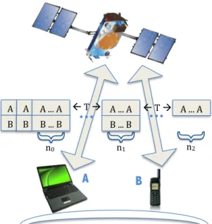
In S-NDMA, the slots in an uplink data channel, from the MTs to the satellite, are orga-nized as a sequence of super-frames, where the MTs’ transmissions are scheduled after a request. Packets are transmitted within epochs, that may involve several MTs and be dis-tributed over up toR+ 1super-frames. Individual packets are firstly scheduled toP+n0 slots in an initial super-frame for P transmitting MTs, wheren0 ≥ 0 defines a number of redundant retransmissions used to improve error resilience. It is assumed that the satellite is capable of discerning all colliding data packets using user-specific orthogo-nal ID sequences defined in the schedule. The initial number of packets’ transmissions allows the separation of all P packets transmitted simultaneously [TZB00]. However, due to channel errors, some of the packets may not be successfully received, so addi-tional slots may be scheduled in future super-frames. An epoch ends when all packets have been correctly received or after the R + 1th super-frame. Besides the scheduling information, the downlink control channel supports the exchange of acknowledgement information about the packets received in each slot. The number of packet transmissions in thesth super-frame is denoted asns, wheres≤R, and the vector with allnsvalues is
denoted asn= [n0, n1, ..., nR]. The time interval between two successive super-frames of
an epoch (used to transmit a given packet),T, is at least above the longest RTT measured by the furthest MT. Therefore, R will be bounded by the delay requirements specified for the QoS traffic class that is being transmitted on a given epoch. It should be noted that H-NDMA defined in [GPB+11] is a special case of S-NDMA, wheren= [0,1,1, ...,1]. This means that S-NDMA trades off a lower delay for a higher energy consumption per packet transmitted. Figure 3.1 illustrates an epoch in the S-NDMA slotted access scheme, whereP = 2MTs are scheduled forR = 2andn = [n0, n1, n2]. MTsAandB transmit
the packets in2 +n0 slots of the first super-frame and inn1 slots of the second. MTB does not transmit in the third super-frame of the epoch, since its packet was successfully received after the second super-frame. Information regarding which packets are received in a given epoch, can be passed to physical level by a matrix present in figure 3.2. This matrix contains information ofP = 4users and a total number of slots allocated to an
epoch ζl = 4, in a case where three terminals transmit on the first epoch, one terminal
3. SATELLITECOMMUNICATIONS 3.2. Medium Access Control Protocol
!
"#! "$
$!
"%!
A
B
&!
'! &!
'! &!(((!&!
'!(((!'!
&!(((!&!
'!(((!'!
&!(((!&!
...
...
!!)!"! !!)!"!
Figure 3.1: S-NDMA Demand Assigned scheme
3. SATELLITECOMMUNICATIONS 3.2. Medium Access Control Protocol
3.2.1 Handling very low power using CDMA
The high distance between satellites and MTs and the limited transmission power in the MTs introduce a challenge in the design of S-NDMA with a large number (hundreds) of retransmissions that allow the correct reception of the transmitted packets. This is not possible in a physical implementation due to the complexity of the H-NDMA receiver algorithm.
This thesis proposes a solution to reduce the H-NDMA receiver complexity. The solu-tion combines H-NDMA and CDMA, and group slots into CDMA frames applying the H-NDMA receiver algorithm to the CDMA frames. This decreases the number of packets handled by NDMA by a spreading factorSf. Besides the lower NDMA complexity, the
noise power is also reduced, due to the channel spreading factor gain. When the narrow band signal is transformed into a CDMA signal by a spread spectrum operation, the orig-inal channel bandwidth is replaced by a channel bandwidthSf times higher. Since the
original bandwidth is now replaced by the bandwidth of the CDMA signal, the spectral efficiency of the system is reduced bySf times. Therefore, theSf value must be chosen
to assure the best trade-off between NDMA complexity and transmission data rate. It should be mentioned that a higher value ofSf decreases NDMA’s complexity and
trans-mission data rate and a lower Sf value does the opposite. A value of Sf = 128 was
chosen for a LEO scenario, by taking into account the mentioned trade-off balance. This number allows the reception of packet with less than ten CDMA frames.
3.2.2 Multipacket Detection Receiver Structure
This thesis considers the uplink transmission of a satellite system with SC-FDE. We adopted the uncoded multipacket detection scheme proposed in [GDB+11] for SC-FDE systems. An analytical expression for the PER is derived there and briefly described in this section.
Nodes contend for the channel at each epoch and collisions might happen. A data block, of N symbols, transmitted by a user pand experiencing multiple collisions, can be ex-pressed, on the time domain, as {sn,p;n = 0, ..., N −1}, and its correspondent on the
frequency domain as {Sk,p;k = 0, ..., N −1}. At the receiver, at the frequency domain,
the received signal from multiple MTs for a given transmissionris
Yk(r)= P
X
p=1
Sk,pHk,p(r)+Nk(r), (3.1)
3. SATELLITECOMMUNICATIONS 3.2. Medium Access Control Protocol
and0≤l≤R, then the receivedP+ζltransmissions are characterized as follows:
Yk = HTkSk+Nk (3.2)
=
Hk,(1)1 . . . Hk,P(1) ... ... ... H(P+ζl)
k,1 . . . H (P+ζl)
k,P
Sk,1 ... Sk,P +
Nk(1) ... N(P+ζl)
k
For a given MTp, the estimated signal at the frequency domain is
˜
Sk,p=
h
Fk,p(1) ... F(P+ζl)
k,p
i
Yk=FTk,pYk. (3.3)
Fk,p corresponds to the feedforward coefficients of the proposed system, and these are
chosen to minimize the mean square error 2σ2E
k,p for a MT p. Considering that Γp =
[Γp,1= 0, . . . ,Γp,p = 1, . . . ,Γp,P = 0]T,2σ2Ek,p is evaluated as follows
2σE2k,p = Eh|S˜k,p−Sk,p|2
i
= FTk,pHTk −Γp
E SkSHk
FTk,pHTk −ΓpH
+FTk,pE
NkNHk F∗
k,p. (3.4)
Regarding E
h
|Sk,p|2
i
= 2σ2S and E
N
(r)
k
2
= 2σ2N, the optimal Fk,p is obtained by
applying the method of Lagrange multipliers to (3.4), which results1
Fk,p=
HHkHk+2σ
2
N
2σS2 IP+ζl
−1 HHkΓp
1− 1
2N σS2
. (3.5)
From (3.4) and (3.5) results
σ2p = 1
N2
N−1
X k=0 E ˜
Sk,p−Sk,p
2
. (3.6)
For a Quadrature Phase Shift Keying (QPSK) constellation and beingQ(x)the well known
Gaussian error function, the Bit Error Rate (BER) of a given userpis
BERp ≃Q
1
σp
. (3.7)
For an uncoded system with independent and isolated errors, the PER for a fixed packet size ofM bits is
P ERp≃1−(1−BERp)M. (3.8)
1It should be noted thatσ2
sandσN2 denote the variance of the real and imaginary parts ofSk,pandN( r)
k
3. SATELLITECOMMUNICATIONS 3.3. Analytical Model
3.3
Analytical Model
This section studies how the throughput, delay, jitter and energy consumption of a de-mand assigned uplink channel in a S-NDMA system are influenced by the PER, trans-mission power and the distance to the satellite. The following modeling conditions were considered:
a) The number of MTs transmitting in a slot, P, is known and follows the schedule defined by the satellite.
b) Perfect average power control, that leads to a uniform averageEb/N0 value for all MTs at the satellite.
3.3.1 Packet Transmission
A packet is transmitted within an epoch, and the system behavior can be modeled by its state during the sequence of super-frames that belong to the epoch. For a demand assigned approach, the uplink schedule is defined by a slot vector n = [n0, n1, ..., nR],
which specifies how many redundant slots are allocated to theP MTs that transmit dur-ing an epoch (besides the initial P slots always defined), in up to a maximum of R+ 1
super-frames.
For a scenario with perfect average power control, it is irrelevant which MTs stopped transmitting during each retransmission super-frame but not the number of MTs that stopped transmitting after a super-frame, due to a successful packet. The system state, denoted by the vector Ψ(l) = {ψ(l)
k , k = 0...l}, can be defined by the number of MTs
whose packets were successfully received and stopped transmitting at the end of the super-frame k = 0, ..., l (assuming l ≤ R retransmission super-frames exist during an epoch). The random variablesψ(kl)satisfy
l
X
k=0
ψk(l)=P , (3.9)
for alll∈[0, R], since the total number of MTs transmitting during the epoch is equal to
P.
The state space of Ψ(l) is an l+ 1-dimension Pascal’s simplex, denoted by the set Ω(l)
P ,
which has a finite number of values for a vector K(l) ∈ Ω(Pl) that satisfy equation (3.9).
Each stateΨ(l) ={ψ(l) 0 =K
(l) 0 , ..., ψ
(l)
l = K
(l)
l }defines the set of transmission sequences,
ς Ψ(l) =K(l)
, whereK0(l) MTs stopped transmitting after the initial P +n0 slots,K1(l) MTs stopped transmitting after the first retransmission super-frame, and so on untilKl(l) MTs stopped transmission at the last retransmission super-frame considered,l≤R. The cardinality ofς Ψ(l)=K(l)
![Figure 2.1: OFDM and SC-FDE — signal processing [FABSE02]](https://thumb-eu.123doks.com/thumbv2/123dok_br/16573819.738120/32.892.224.619.273.431/figure-ofdm-sc-fde-signal-processing-fabse.webp)
![Figure 2.2: Spectral-efficiency bound as a function of noise-spectral-density-normalized energy per information bit N0Eb [BFC05]](https://thumb-eu.123doks.com/thumbv2/123dok_br/16573819.738120/37.892.207.711.200.509/figure-spectral-efficiency-function-spectral-density-normalized-information.webp)