Fábio Adriano Seixas Lopes
Licenciado em Ciências de EngenhariaEletrotécnica e de Computadores
Intelligent IoT and Dynamic Network
Semantic Maps for more Trustworthy
Systems
Dissertação para obtenção do Grau de Mestre em Engenharia Eletrotécnica e de Computadores
Orientador: Doutor Ricardo Luís Rosa Jardim Gonçalves, Professor Auxiliar com
Agregação, Faculdade de Ciências e Tecnologia da Universidade
Nova de Lisboa
Co-orientador: Doutor Carlos Manuel Melo Agostinho, Professor Auxiliar
Convidado, Faculdade de Ciências e Tecnologia da Universidade
Nova de Lisboa
Júri:
Presidente: Prof. Dr. Luís Bernardo
Arguente: Prof. Dr. José Oliveira
Vogal: Dr. Carlos Agostinho
Intelligent IoT and Dynamic Network Semantic Maps for more Trustworthy Systems
Copyright © Fábio Adriano Seixas Lopes, Faculdade de Ciências e Tecnologia, Universidade Nova de Lisboa.
Acknowledgements
I would like to thank all the people who supported me during the realization of my course and, in some way, contributed to this dissertation.
First, I would like to thank my family, specially my parents and brother, which supported me during these academic years and never gave up on believing in me. They always did it with an enormous willingness to help and I am very fortunate to have them in my life.
To my advisor, Dr. Ricardo Gonçalves, and the local coordinator of C2NET project, Dr. Carlos Agostinho, for giving me the great opportunity of working in a GRIS’s project and believing in my capabilities. Their guidance, throughout the development of this dissertation, was a key factor to complete the objectives that I set to accomplish.
To all the people at GRIS, but specially to José Ferreira that helped me, during this dissertation, in many ways, with his great knowledge and for believing in my work, pushing me to do better and to successfully complete this dissertation.
Abstract
As technology evolves, the Internet of Things (IoT) concept is gaining importance for constituting a foundation to reach optimum connectivity between people and things. For this to happen and to allow easier integration of sensors and other devices in these technologic environments (or networks), the configuration is a key process, promoting interoperability between heterogeneous devices and providing strategies and processes to enhance the network capabilities. The optimization of this important process of creating a truly dynamic network must be based on models that provide a standardization of communication patterns, protocols and technologies between the sensors. Despite standing as a major tendency today, many obstacles still arise when implementing an intelligent dynamic network. Existing models are not as widely adopted as expected and semantics are often not properly represented, hence resulting in complex and unsuitable configuration time. Thus, this work aims to understand the ideal models and ontologies to achieve proper architectures and semantic maps, which allow management and redundancy based on the information of the whole network, without compromising performance, and to develop a competent configuration of sensors to integrate in a contemporary industrial typical dynamic network.
Resumo
Com a evolução da tecnologia, o conceito de Internet das Coisas está a ganhar importância por constituir uma fundação que permite alcançar a conetividade ideal entre pessoas e coisas. Para isto acontecer e para facilitar a integração de sensores e outros dispositivos nestes ambientes tecnológicos (ou redes), a configuração é um processo chave, que promove a interoperabilidade entre dispositivos heterogéneos e providencia estratégias e processos para realçar as capacidades da rede. A otimização deste importante processo de criar uma rede verdadeiramente dinâmica deve ser baseada em modelos que permitem uma normalização de padrões de comunicação, protocolos e tecnologias entre os sensores. Apesar de ser uma grande tendência atualmente, muitos obstáculos ainda surgem quando se implementa uma rede dinâmica inteligente. Os modelos existentes não são tão amplamente adotados como seria de esperar e a semântica tende a não estar representada apropriadamente, resultando em configurações complexas e demoradas. Assim, este projeto consiste em perceber os modelos ideais e as ontologias para atingir arquiteturas e mapas semânticos adequados, que permitem a gestão e redundância baseada na informação da rede inteira, sem comprometer o desempenho, e para desenvolver uma configuração de sensores competente para implementar numa rede dinâmica típica da indústria contemporânea.
Table of Contents
Acknowledgements ... vii
Abstract ... ix
Resumo ... xi
Table of Contents ... xiii
List of Figures ... xvii
List of Tables ... xxi
Table of Acronyms ... xxiii
1 Introduction ... 1
1.1 Motivation Scenario - IoT... 2
1.2 Research Question ... 3
1.3 Hypothesis and Approach ... 4
1.4 Work Methodology ... 5
1.5 Dissertation Outline ... 5
2 IoT Models and Networks ... 7
2.1 Internet of Things ... 7
2.2 IoT Models ... 8
2.2.1 IoT-A Reference Architecture ... 8
2.2.2 W3C SSN Ontology ... 15
2.2.3 IoT Lite ... 18
2.2.4 Discussion... 19
2.3 Semantics and Concepts of Intelligent Sensor Networks ... 21
2.3.1 Sensor Configuration ... 22
2.4 Dynamic Network Communication ... 26
2.4.1 Discussion towards Semantic Maps ... 28
3 Semantic Mapping ... 31
3.1 Overview ... 31
3.2 Concept Proposed ... 41
3.3 System Architecture ... 45
3.3.1 CEP ... 46
3.3.2 Devices ... 47
3.3.3 Device Knowledge Base (C2NET Ontology) ... 47
3.3.4 Mapping Knowledge Base (SMAP Ontology) ... 49
3.3.5 Semantic Mapping Module (SMAP)... 50
3.4 Potential Application Scenario ... 52
4 Proof of Concept Implementation ... 57
4.1 Requirements and Functionalities... 57
4.2 Technological Specifications ... 59
4.3 Implementation Steps ... 61
4.3.1 Step 1 – Designing the Architecture ... 61
4.3.2 Step 2 – Creation of Models and Instances on Protégé ... 61
4.3.3 Step 3 – Jena and Esper setup on Eclipse with Java ... 66
4.3.4 Step 4 – SPARQL Queries and manipulation of OWL files ... 66
4.3.5 Step 5 – Sensor Threads ... 67
4.3.6 Step 6 – Fault Detection (by Esper and by Ontology) ... 68
4.3.7 Step 7 – Recovery with Semantic Maps ... 69
4.3.8 Step 8 – Implementation of a Graphical User Interface ... 69
5 Testing and Hypothesis Validation ... 73
5.1 Testing Methodology ... 73
5.3 Hypothesis Validation ... 90
5.4 Scientific Validation ... 91
5.5 Industrial Validation ... 92
5.5.1 SMAP in C2NET ... 92
5.5.2 IoT Network Configuration in the Metalworking Case ... 93
6 Final Considerations and Future Work ... 97
6.1 Main Results ... 97
6.2 Conclusions ... 98
6.3 Future Work ... 100
List of Figures
Figure 1-1: Internet Of Things Impact (Kastelein, 2012). ... 1
Figure 1-2 - A IoT-A High Level Representation of the Reference Model and Reference Architecture (Bauer et al., 2012). ... 2
Figure 1-3 - : Internet Of Things Concept Illustration (Intersog, 2016). ... 3
Figure 2-1: IoT-A Reference Model Building Blocks(Unis et al., 2013). ... 8
Figure 2-2 - The IoT-A Tree (Bauer et al., 2012). ... 9
Figure 2-3 - Interaction of all sub-models in the IoT Reference Model (Unis et al., 2013). ... 10
Figure 2-4 - IoT Domain Model (Unis et al., 2013). ... 11
Figure 2-5 - IoT Information Model (Unis et al., 2013). ... 12
Figure 2-6 - IoT Functional Model (Unis et al., 2013). ... 13
Figure 2-7 - Interoperability Aspect of the IoT Communication Model (Unis et al., 2013). ... 14
Figure 2-8: The SSN Ontology (Compton, Barnaghi, & Bermudez, 2011). ... 15
Figure 2-9: The Stimulus-Sensor-Observation Pattern (Compton et al., 2011). ... 16
Figure 2-10: IoT-Lite Ontology (Bermudez-edo, Elsaleh, et al., 2015). ... 19
Figure 2-11 - Example of mapping between two ontologies (Ferreira, 2012). ... 21
Figure 2-12 - Context-Aware Sensor Configuration Model – CASCoM (Perera, Zaslavsky, Compton, Christen, & Georgakopoulos, 2013a). ... 23
Figure 2-13 – Context Aware Concept (Cisco, 2008). ... 24
Figure 2-14 – Self-Adaptation Concept (Weiss, Zeller, & Eilers, 2010). ... 25
Figure 2-15 - System Architecture of the CADDOT model (Perera, Jayaraman, et al., 2013). .. 26
Figure 2-16 - CADDOT Model for Sensor Configuration (Perera, Jayaraman, et al., 2013). ... 27
Figure 2-17 - Example of Relations (Paiva, 2015). ... 29
Figure 3-1 - CEP Generic Concept. ... 31
Figure 3-3 - Example of Solution to a Sensor Failure. ... 33
Figure 3-4 Example of Sensor Malfunctioning. ... 33
Figure 3-5 - Semantic Mapping Model. ... 38
Figure 3-6 - Device KB and Mapping KB. ... 40
Figure 3-7 - System Architecture. ... 40
Figure 3-8 - Activity Diagram of the Architecture’s Process. ... 42
Figure 3-9 - Sequence Diagram of the Architecture’s Process. ... 43
Figure 3-10 - Activity Diagram of the Design Process. ... 44
Figure 3-11 - Sequence Diagram of the Design Process. ... 45
Figure 3-12 - CEP Overview (Seeger, 2012). ... 46
Figure 3-13 – Device Knowledge Base Class Diagram. ... 47
Figure 3-14 – Fault Detection Class Diagram (with 3 Example Techniques). ... 48
Figure 3-15 - Mapping Knowledge Base Class Diagram. ... 49
Figure 3-16 - Smart Factory Room Map Example. ... 55
Figure 4-1 - C2NET Ontology OntoGraf. ... 62
Figure 4-2 - C2NET Ontology OntoGraf Extended. ... 63
Figure 4-3 - Individual Property Assertions Example. ... 64
Figure 4-4 - Mapping Ontology OntoGraf. ... 64
Figure 4-5 - Mapping Ontology OntoGraf Extended. ... 65
Figure 4-6 - SPARQL Query Example. ... 67
Figure 4-7 - EPL Statement Example ... 68
Figure 4-8 - SMAP Graphical User Interface. ... 70
Figure 5-1 – Example Scenario of Testing Implementation. ... 75
Figure 5-2 - Infrared Sensor. ... 76
Figure 5-3 - Ultrasonic Sensor. ... 76
Figure 5-4 - Room 1: Start Room. ... 77
Figure 5-6 - Room 1: Failure in a Sensor. ... 79
Figure 5-7 – Room 1: Semantic Maps for the Faulty Sensor. ... 79
Figure 5-8 - Room 1: Result of the use of a Semantic Map. ... 80
Figure 5-9 - Temperature Sensor... 82
Figure 5-10 - Room 2: Changing the Sensor State. ... 82
Figure 5-11 - Room 2: Sensor State changed. ... 83
Figure 5-12 - Room 2: Inconsistency and Comparison Failures Detected... 83
Figure 5-13 - Room 2: Use of a Semantic Map with two Destination Sensors. ... 84
Figure 5-14 - Room 2: Resulting Network State. ... 85
Figure 5-15 - Room 3: Initial Network State... 87
Figure 5-16 - Room 3: Semantic Map. ... 88
Figure 5-17 - Room 3: Network after the Semantic Map. ... 88
Figure 5-18 - Room 3: Room Paused. ... 89
Figure 5-19: C2NET Project Overview. ... 92
Figure 5-20 - Hardware for the C2NET implementation in AAMM. ... 94
Figure 5-21 - C2NET Implementation in the AAMM factory. ... 94
List of Tables
Table 2-1 – IoT Models Comparison. ... 20
Table 3-1 - Semantic Mismatches (Ferreira, 2012), based on (Agostinho et al., 2011). ... 37
Table 3-2 - Examples for Possible Objectives of Sensing Devices in the Application Scenario. 53 Table 5-1 - Test Case 1. ... 78
Table 5-2 - Test Case 2. ... 81
Table 5-3 - Test Case 3. ... 86
Table of Acronyms
Acronyms Definition
AAMM António Abreu Metalomecânica
ARM Architecture Reference Model
CADDOT Context-Aware Dynamic
Discovery of Things
CAN Controller Area Network
CASCoM Context-Aware Sensor
Configuration Model
CEP Complex Event Processing
DB Database
EDA Event-Driven Architecture
EPA EPL EU FD
Event Processing Agent Event Processing Language European Union Functional Decomposition FG GRIS GUI ID IDE Functionality Groups Group for Research in Interoperability of Systems Graphical User Interface Identifier
Integrated Development Environment
IEC International Electrotechnical
Comission
Electronics Engineers
IoT Internet Of Things
IoT-A Internet Of Things Architecture
IP Internet Protocol
ISO
IT
International Organization for Standardization
Information Technology
KB Knowledge Base
M2M Machine to Machine
OSI Open Systems Interconnection
OWL Web Ontology Language
PIR Passive Infrared
RFID Radio-Frequenct Identification
RW Real World
SME Small and Medium-Sized
Enterprises
SOTA State Of The Art
SOI Situation of Interest
SSN Semantic Sensor Network
SSO Stimulus-Sensor-Observation
TTCN Tree and Tabular Combined
Notation
UDP User Datagram Protocol
UML Unified Modelling Language
UNINOVA Institute for the Development
of New Technology
W3C World Wide Web Consortium
1
Introduction
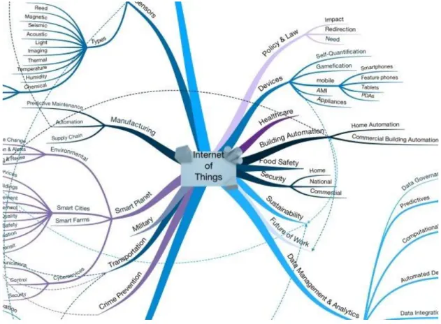
Imagine a world where billions of objects can sense, communicate and share information, all interconnected over public or private networks. These interconnected objects have data regularly collected and analysed, providing a wealth of intelligence for planning, management and decision-making. This is the world of the Internet Of Things or IoT (Infocomm Development Authority, 2012). This concept represents various possibilities for a wide range of areas related, or to be related, in the future, to technology as we can see in Figure 1-1.
Figure 1-1: Internet Of Things Impact (Kastelein, 2012).
To overcome the existing heterogeneity of devices, which use and demand different technologies to function, models of Reference Architectures are required. Some existing efforts to solve this problem are the IoT Architecture, the W3C SSN Ontology and the IoT Lite, reviewed in further chapters of this work. Other ontologies exist, but aim to different subjects or are not as useful to this work as the ones mentioned before.
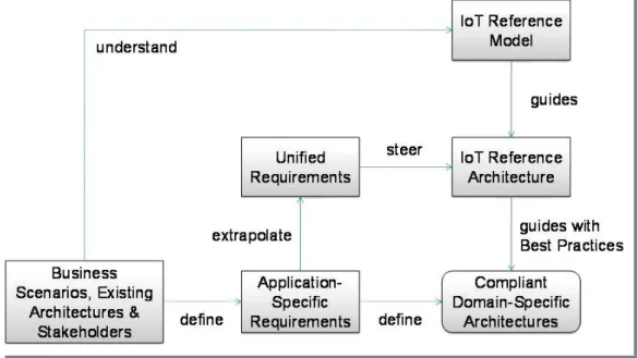
This work aims to contribute to the contemporary methodology regarding the existing models for Reference Architectures in the Internet of Things environment by analysing them and understanding how they can contribute for a standardization of configuration and mapping of IoT devices to maximize compatibility, interoperability, safety and quality within an IoT network. In Figure 1-2, the dependencies and influences of a functional IoT model are abstractly presented.
Figure 1-2 - A IoT-A High Level Representation of the Reference Model and Reference Architecture (Bauer et al., 2012).
The next section will provide some contextual information about the scenario and the motivation that lead to this topic. After that, the research question, hypothesis, approach and work methodology of this dissertation are presented.
1.1
Motivation Scenario - IoT
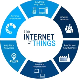
The concept is based on machine-to-machine communications and interactions between objects, devices and people (Bermudez-edo, Elsaleh, Barnaghi, & Taylor, 2015). The
term was coined in 1998 and later defined as “The Internet Of Things allows people and
things to be connected Anytime, Anyplace, with Anything and Anyone, ideally using Any
path/network and Any service” (Vermesan et al., 2009). In the following image (Figure 1-3),
the ideology referenced by the definition of the term is illustrated.
Figure 1-3 - : Internet Of Things Concept Illustration (Intersog, 2016).
In few words, IoT is the concept of connecting any device (such as cell phones, televisions, lamps and refrigerators) to the Internet and achieve broad connectivity to provide complex tasks or to make them easier. The potential is immeasurable and it is estimated that by 2020 the number of connected devices will grow to 26 billion (Rivera & Van der Muelen, 2013). The IoT can become a giant ubiquitous interoperable network of interconnected
“things” (which will also include people) and has the potential to be applied to home
automation or other concepts like “smart cities”, to help us reduce waste and improve energy efficiency.
The main motivation and focus of the research and development of this dissertation lays in the construction of semantic maps and configuration of devices, such as sensors, in a IoT domain, to achieve an intelligent and efficient network monitoring system. The idea behind the use of semantic maps is to gather and specifically organize the information of the network and its components, to allow redundancy by recovering from device errors/failures. For this, proper models must be studied, compared and implemented, to develop a useful solution for contemporary and future IoT environments.
1.2
Research Question
The general theme for this dissertation can be generally described as “Dynamic
network and its devices, specifically sensors due to its importance in dynamically adapt to the environment, to allow the creation of this specific data structures, the semantic maps, that aim to allow alternative configurations, redundancy and analyse the overall performance of the domain.
Thus, to properly define the procedures of the research work needed and to emphasize the objective of this work, it is important to formulate the research question that this thesis aims to answer during its completion.
RQ
:
“Is it possi
ble to use meta-information from network sensors to
build semantic maps to support the analysis of degrees of similarity,
alternative configurations and trustworthiness of systems
?”
This question provides some guidance during the development of this thesis and the answer is going to result from the necessary system implementation, validation and assessment.
1.3
Hypothesis and Approach
Based on the researched information and the research question, provided before in this chapter, this thesis is conducted regarding the following formulated hypothesis:
“
If it is possible to use meta-information from network sensors and
contextually analyse it, then we can dynamically build semantic maps
in order to develop a more trustworthy and intelligent network,
capable of reacting to the surrounding ecosystem constraints and
variability.
”
1.4
Work Methodology
To achieve the best outcome possible with the development of this thesis, it is important to define the necessary processes needed to an efficient scientific investigation and experimentation. The information and data here presented is based on the stages required for this particular topic, the recommendations of the thesis supervisors and classical scientific methodology bibliography (Nordgren, 2004), (Camarinha-Matos, 2012a), (Camarinha-Matos, 2012b) and (Chinneck, 1999).
According to an adaptation of the information from the sources previously mentioned, the selected main phases considered for this dissertation are:
1. Research Questions - Relates to a specific problem or area of knowledge, which has interest, for the author, to develop a question with the objective of improving an existing solution, finding some new aspect or solve a particular issue.
2. Context Observations - Includes observations and background information about the problem in study.
3. Hypothesis - Typically, is as an “educated guess” and is formed as a statement, that is proposed as an answer to the research question.
4. Experimentation - Is the phase where the experiment is planned in order to test the hypothesis. Considers several aspects such as variables, control, observation and methods of data collecting. It may result in a prototype or simulation environment to be tested, to allow the retrieval of significant data. In this case, the experimentation context is related to the C2NET project (C2NET, 2015), which is properly detailed further in this dissertation.
5. Results Analysis- The results are usually in the form of a statement that explains or interprets the data. It could provide a positive answer to the formulated hypothesis or it can prove it wrong. In the last case, further different hypothesis should be formulated or the problem (research question) must be reconsidered. In either case, positive or negative results are considered helpful for the scientific community.
6. Thesis Writing and Publishing - This last phase includes the explanation and conclusion of the entire work, in this case, in a dissertation.
1.5
Dissertation Outline
Chapter 2 – IoT Models and Networks: This section presents the research of contemporary solutions and concepts for the relevant subjects of this dissertation. After the initial contextualization in the IoT paradigm, the studied models of architecture are presented and briefly discussed regarding the aspects that are important for this thesis. Finally, the main aim for this thesis is introduced, Semantic Maps, and relevant topics, such as sensor configuration and network concepts, are described and integrated in the environment of this work.
Chapter 3 – Semantic Mapping: In this chapter, an overview of the architecture considered in this dissertation is presented and explained. This architecture attempts to describe, on a high level, the solution for the module designed that will implement the concept of semantic maps.
Chapter 4 – Proof of Concept Implementation: This chapter introduces the design process of the proposed solution and includes a detailed report about the practical component of this thesis along with a thorough explanation on what it consists and why it was considered in that way.
Chapter 5 - Testing and Hypothesis Validation: In this section, the tests used to validate the formulated hypothesis and the respective analysis are presented. The contexts provided for the experiments detailed in this chapter are designed to embody real world environments, to ensure the accuracy of the provided solution and methodology, and following the demands of the foreseen integration and validation with other related research activities.
2
IoT Models and Networks
In this section, an overview of the researched scientific literature about this dissertation is presented. The Internet of Things sub-section is a complement to the information already mentioned in the introduction chapter and addresses the relation with the rest of the sub-sections. The IoT Models sub-section presents an overview of the contemporary approach on IoT architectures, how they function and what advantages we may take from them. Finally, the last two sub-sections of this chapter, present the gathered information about the major issues of creating a dynamic and intelligent sensor network through semantic mapping, sensor configuration and environment awareness.
The objective of this initial investigation is to form an efficient basis for the implementation and further work, explained in the further chapters, and to understand the concerning main concepts. Further specific research about the development of this dissertation may be presented in other chapters, to allow a better understanding of the mentioned and used concepts.
2.1
Internet of Things
During the previous chapter of introduction, the definition and concept of Internet of Things was explained in order to set the scenario that motivates the development of this work. With that in mind, this sub-section is only focused on the relation that emerges with the need for IoT reference architectures, models and ontologies.
The correct configuration, regarding efficient ontologies for these components, is believed to be the key for a successful implementation, because it provides the needed tools and contexts to successfully integrate and configure sensors in order to manage them, or give them the capability of managing themselves, and be able to monitor and act on the network as a whole.
2.2
IoT Models
A model is a definition of some slice of reality which is being observed and interpreted, that is designed through the use of abstract elements and relationships in order to correspond to real scenarios and environments (Correia, 2010).
An IoT Model aims to tackle the problems mentioned above, in a generic way. They usually propose a high-level reference architecture or ontology that establishes identities, procedures, configurations and relationships between different entities in various domains, to support any emergent idea or concept related to the Internet of Things. To understand the importance of these models, it is going to be mentioned some of the most prominent and widely available. Some other IoT models like IBM Watson, Cisco IoT System, Google Brillo, Z-Wave, Osmose, Sensei and DUL are also known, but are not as widely spread, available or relevant to the subjects of this work.
2.2.1 IoT-A Reference Architecture
In this model, the European Lighthouse Integrated Project, addresses the structural concerns related to the Internet of Things and creates a proposal for an Architectural Reference Model (ARM), starting with the definition of an initial set of key building blocks regarding functionality, scalability, performance, deployment and security, with the purpose to eventually derive into a large set of concrete IoT architectures.
Figure 2-1: IoT-A Reference Model Building Blocks(Unis et al., 2013).
Architectural Reference Model, the Reference Architecture is the reference for building compliant IoT Architectures and the Guidelines are how these models, views and perspectives can be concretely used.
The IoT-A is often presented with a metaphor of a tree, not to be interpreted too strictly, as seen in Figure 2-2.
Figure 2-2 - The IoT-A Tree (Bauer et al., 2012).
The roots of the tree include selected groups of communication protocols (such as WiFi, ZigBee, IPv6 and RFID) and device technologies (such as sensors, actuators and tags). These protocols and devices are in fact the base of an efficient and interoperable IoT model, because by achieving complete understanding and commitment between them, full connectivity is reached and exchanging information can become an easy task. The leaves of the tree represent the wide variety of IoT applications that can be built from the trunk. The leaves only succeed if the roots have a proper functioning and for this functioning to be useful, the trunk must have an incisive and correct approach on the way the devices and protocols work with each other. The trunk is represented here as the Architectural Reference Model (ARM).
Figure 2-3 - Interaction of all sub-models in the IoT Reference Model (Unis et al., 2013).
To better understand the general architecture of this model, an explanation of some inherent concepts is presented next (Virtual/Physical Entities, Sensors/Actuator/Tags and others). These concepts are transversal to other models and are heavily mentioned during further chapters of this thesis. After this, some information about the sub-models, that form the IoT Reference Model, is provided.
• Sensors, Tags and Actuators - A sensor provides information about the physical environment it monitors. Tags are used to identify physical components of a system, usually they need to be read using specific sensor devices. Actuators are responsible for actions requested by the system, or user, and express modifications in the physical state of the environment.
• Physical and Virtual Entities - “An entity is anything that has a distinct existence” (Rannenberg, Royer, & Deuker, 2009), physically or virtually. The designations mentioned are, in this context, directly associated with physical and virtual representations of certain elements of an IoT system. The representations may be directly linked, for example, a physical entity is represented by the corresponding virtual entity or to a group of virtual entities and vice versa. It can even not be any links and these connections may appear and disappear during the operation of the system.
information to be used by a computer system. They are known to be a type of database but with a more specific purpose to systems and intelligent decision.
• Simple and Complex Events - A simple event is usually referred to as an action (or component), usually a time observation, which results from the operation of a system or derives from it. A complex event derives from various (two or more) simple events and requires much more processing and allows much more complex solutions.
• Complex Event Processing (CEP) - The CEP consists in reading and analysing information about events and to deduce conclusions about them. The complex event processing combines information from various sources or devices to infer events or patterns that suggest more complicated circumstances. The objective of this method is to identify important events (such as opportunities or threats) and respond quickly and effectively.
2.2.1.1 Domain Model
It is the foundation of the Reference Model and describes all the relevant concepts in the Internet of Things like devices, services and virtual entities, and the relationships between them. It also provides a common lexicon and taxonomy of the IoT domain (Muller, 2008).
The main purpose of a domain model is to generate a common understanding of the target domain in question. Such common understanding is important because provides the possibility to argue about architectural solutions and to evaluate them (Unis et al., 2013).
In Figure 2-4, we can see the definition of basic attributes of the concepts related to the IoT systems and the way they interact. The software components are layered upon the hardware components to extend them to the virtual world where decision-making occurs, using the model and functional principles. The decisions and reasoning are then passed to the hardware part for the interaction with the environment.
2.2.1.2Information Model
Defines the structure (relations and attributes) of IoT related information in a system on a conceptual level. It can be seen as a meta-model that provides a structure for the information to be handled by IoT systems (Unis et al., 2013). That structure provides representation, processing, storage and information retrieval to the system.
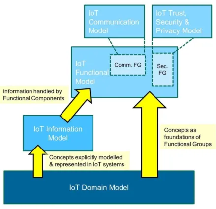
The IoT Information Model represents all the concepts of the Domain Model that are to be explicitly represented and manipulated in the digital world (Unis et al., 2013).
In this model, the information of the virtual entities is organized and defined using relevant context for possible applications of the various components. The resultant structure of the information represented in the Figure 2-5 shows how it is handled and processed in an IoT system.
2.2.1.3 Functional Model
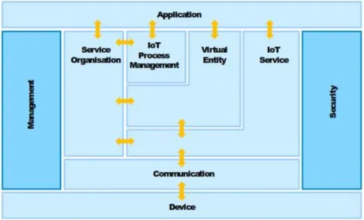
Identifies groups of functionalities and their interactions as seen in Figure 2-6. The functional model is an abstract framework for understanding the Functionality Groups (FG) that are explained by Functional Decomposition (FD), which is the process to identify and relate each FG to the others. With this process, the complexity of the system is divided into smaller and more manageable parts.
Figure 2-6 - IoT Functional Model (Unis et al., 2013).
In Figure 2-6 is depicted the derivation of the model. From the main concepts of the Domain Model (Virtual Entities, Devices, Resources and Users) others emerge like the Application, Virtual Entity, IoT Service and Device components. From the need to communicate and exchange information to support the IoT system, the Communication component is presented and included. The requirements to build services and applications are covered by the IoT Process Management and Service Organization. To address the concern about IoT Trust, Security and Privacy, the Security component is identified. Finally, the Management is a transversal component required for the management and interaction between the functional groups.
2.2.1.4 Communication Model
efficiently exchanging information. The proposed model is based on the ISO OSI 7-layer model for networks and it highlights the aspects about interoperability among different stacks.
Figure 2-7 - Interoperability Aspect of the IoT Communication Model (Unis et al., 2013).
The Figure 2-7 emphasizes the interoperability aspects that the IoT Communication Model wants to develop in comparison to the ISO/OSI stack (presented on the right of the figure). The dashed lines were used for highlighting the IoT aspects relatively to the stack layers. This transversal approach allows the existing protocol stacks, after the system is modelled according to the IoT specifications and interoperable needs, to be adapted easily. 2.2.1.5 Trust, Security and Privacy Model
In practical applications, this model defines some characteristics to consider when building a safe system. The model of this aspect of IoT systems was not defined entirely but there were considered many guidelines, methods and protocols to ensure trust, security and privacy without damaging the system’s efficiency. We will review the relevant concepts of this model without stepping too further into the protocols or specifications described in this model.
Trust regards the aspects of authentication when dealing with other entities and exchanging sensitive information with them. To properly achieve the compliance needed to the expected functional behaviour, all entities, protocols and mechanisms in an IoT system must be validated. Some mechanisms that allow this process are protocols for integrity and confidentiality, endpoint authentication, non-repudiation methods, behaviour policies and a trust anchor (entity to be trusted by default).
Privacy regards non-authorized information spreading and security management in data banks. Due to the variety of entities that handle data in IoT, guaranteeing data privacy is an essential but difficult feature. To accomplish this, mechanisms of access policies, encryption/decryption algorithms, security and management credentials can be used.
2.2.1.6 Review
In this sub-section, it was presented a very broad and complete model for organizing an IoT architecture. The reference model and sub-models, define the basic concepts, terminologies and relationships in the IoT ARM. This architecture is very complete and represents one step further in defining the IoT reference architecture, but it lacks the applicability that other more specific ontologies have proposed due to a less care for specific implementations and real-world situations.
2.2.2 W3C SSN Ontology
In this model, an OWL is used, an international standard for encoding and exchanging ontologies designed to support the Semantic Web. The concept of Semantic Web is that information should be given explicit meaning, so that machines can process it more intelligently (Heflin, 2006).
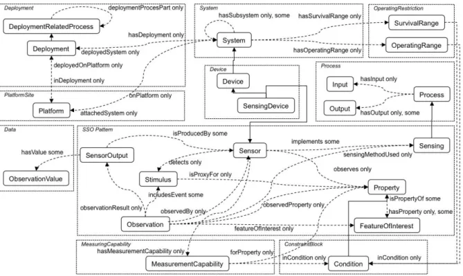
Figure 2-8: The SSN Ontology (Compton, Barnaghi, & Bermudez, 2011).
this way, the ontology is better positioned to provide modularity and reusability. The key specifications of the sensor information are based on their accuracy, the observations and methods used for sensing, the concepts for operating and, related with the structure for field deployments, the deployment lifetime and sensing purpose. The ten conceptual modules, key concepts and relations are shown in Figure 2-8.
The SSN Ontology is built around a central pattern describing the relationships between sensors, stimulus and observations, the Stimulus-Sensor-Observation (SSO) pattern (Compton et al., 2011). The ontology is divided into four main perspectives:
• A sensor perspective (what senses, how it senses and what is sensed);
• A data or observation perspective (observations and related metadata);
• A system perspective (systems of sensors and deployments);
• A feature and property perspective (what senses a particular property or what observations have been made about it).
2.2.2.1 The Stimulus-Sensor-Observation (SSO) Pattern
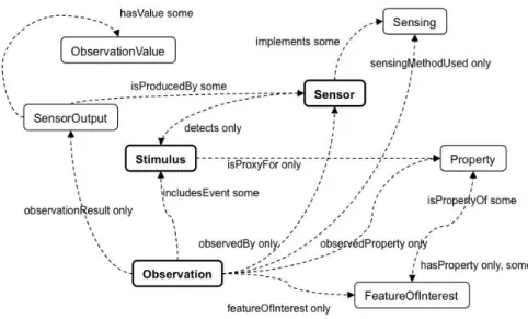
The SSO pattern, as seen in Figure 2-9, links sensors, what they sense and the observations that result, considering three of the four main perspectives mentioned before (the system perspective is more about system organisations and deployments than sensing, but it surely relates to the SSO Pattern).
Figure 2-9: The Stimulus-Sensor-Observation Pattern (Compton et al., 2011).
Stimuli
Sensors
Sensors are usually physical objects that observe, transforming incoming stimuli into another, often digital, form of representation. This new representation normally comprises the need to handle the obtained information in data computation. Sensors may be hardware devices, sensing systems or anything that somehow senses.
Observations
Observations are essentially the core of this pattern. For a specific sensing event, an observation can link the act of sensing, the event that is the stimulus, the observing sensor, the sensing method used, a result and an observed feature and property, with the objective of placing all of them in an interpretative context.
2.2.2.2 Perspectives
Sensor Perspective
The SSO pattern describes a sensor in terms of its stimulus, sensing method and the observations it makes (Compton et al., 2011). This perspective also includes the capabilities of the sensors. For each property that a certain sensor can observe, the performance and accuracy of the sensor might be influenced by environmental conditions related or not to the property under observation.
The accuracy is an observable property of the sensor, generally defined has the maximum difference that will exist between the actual value and the indicated value at the output of the sensor (Carr & Brown, 2000), often mentioned by a data sheet that lists properties observed in various conditions that also include precision, resolution and measurement range. A sensor may have various measurement capabilities, describing the capability of the sensor in various situations, which are themselves observable properties of
the sensor’s environment. A measurement capability instance collects observed properties of
a sensor in the conditions specified. A sensor may have links to any number of instances for determining capability in various situations.
Observation Perspective
The observation perspective places a context for interpreting incoming stimuli, the observing event and the stimulus. The context includes the observed feature, property, observing sensor, result and method from the previously described pattern and can also report a quantitative approximation of quality of the observation, a time that the result became available and a time at which the sampling occurred.
System Perspective
that have operating and survival ranges and may be deployed on certain platforms. Similarly, to how prevailing environmental conditions may affect the performance of a sensor, a system or device may have a defined operating environment, and environmental extremes may exceed the capacity of a system to survive and make further observations (Compton et al., 2011). The means for describing operating and survival ranges are the same as for sensors and measurement capabilities because they are observable properties of the systems. The operating range includes features such as power range, power sources and standard configurations. The survival range describes standard environmental conditions to which the sensor can be exposed without suffer predictable damage.
To this perspective is also relevant to mention the deployment, which is a process that includes all phases in the lifetime of an operating system such as installation, maintenance and further deactivation. A system is generally deployed on a platform. The location of platforms, systems or sensors and temporal properties of deployments can be abstractions of real-world locations or also absolute or relative locations.
2.2.2.3 Review
This OWL ontology, describes a specific straightforward approach to sensors, sensing, measurement capabilities of sensors, observations that result from sensing and deployments, or field applications, in which the sensors are used. The configuration, in this ontology, can be represented as an adaptive process which provides an interesting base for the objective of this work. The network is visualised in modules to provide better reusability and adaptation based on sensor observation. It lacks additional information regarding sensor relative entities and the domains where they are used, which means that this ontology has to be complemented with other ontologies or models in order to develop an efficient practical solution.
2.2.3 IoT Lite
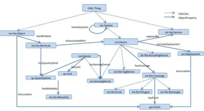
The IoT Lite is a lightweight ontology, based on the SSN Ontology, to represent Internet of Things resources, entities and services (Bermudez-edo, Elsaleh, et al., 2015). By creating a representation, in a more lightweight approach than previously existed in other ontologies, it is possible to achieve an ontology able to provide shorter response time and thus create a more efficient structure for systems.
Figure 2-10: IoT-Lite Ontology (Bermudez-edo, Elsaleh, et al., 2015).
The IoT-Lite is meant to be used with a quantity taxonomy, that allows discovery and interoperability of IoT resources in heterogeneous platforms using a common vocabulary (Bermudez-edo, Elsaleh, et al., 2015).
2.2.3.1 Review
The IoT Lite Ontology is a meta ontology designed to be extended in order to represent IoT concepts. It also focuses more on sensing and establishes a high-level concept on actuation, which allows any future developments or adaptations on this area. It is a lighter view of the SSN Ontology, ideal for environments or specific situations in such environments, that require fast and easy processing. It also can be combined with ontologies representing IoT data streams (Bermudez-edo, Elsaleh, et al., 2015) like the SAO Ontology which focuses on representing, semantically, the features of a data stream in the IoT environment (Kolozali, Barnaghi, & Bermudez, 2016).
2.2.4 Discussion
are unsuitable for dynamic and responsive environments such as the IoT. A model so complete as the IoT Architecture tends to be difficult to apply due to existing various aspects and constraints that the developer must deal with before even started implementing. Some more specific models like the SSN Ontology and IoT Lite, are incisive on the problem they want to solve. This author believes that by developing such ontologies for more specific solutions, or even consider them protocols (to enforce its use), creates a bigger opportunity for the scientific community to excel in the field they wish to improve, instead of dissolving into a solution, usually not giving importance to minor but still important problems, for the immensity that is the IoT environment. Nevertheless, semantic technologies are widely claimed to be a qualitatively stronger approach to interoperability than contemporary standards-based approaches (Lassila, 2005).
In Table 2-1, a comparison of the studied models is provided for better understanding. Some ontologies excel where others present weaker or inexistent solutions, which means that different applications may need different ontologies or a combination of some of them.
Table 2-1 – IoT Models Comparison.
W3C SSN IoT-A IoT Lite
Interoperability ✓ ✓ ✓
Device Discovery and Management
✓ ✓ ✓
Scalability ✓ ✓ ✓
Management of Large Volumes of Data
✓ ✓
Security, Privacy, and Integrity
✓
Dynamic Adaptation ✓ ✓
Fast Processing ✓
Context Awareness
The concept of combining ontologies is not new and, most of the cases, represents the more suitable solution. But adapting models to each other is an absurd idea because they represent base concepts and ideas to provide guidance for developers and should not be changed or else they would turn every already developed project obsolete. So, to provide a suitable solution, model mapping (or ontology mapping) is briefly described.
going to be mentioned in further chapters due to its importance in semantic mapping (i.e. the creation of semantic maps).
Figure 2-11 - Example of mapping between two ontologies (Ferreira, 2012).
After reviewing the different solutions, previously presented, and briefly introducing the possible mapping between them, the possibility to represent a sensor network in a model gains shape and provides a platform with new features and ideas that improve the capabilities of the network. In the next chapters, important concepts that provide such capabilities are presented, namely sensor configuration, which arises as the basis for the correct integration of the sensors and is the motto for the upcoming concepts related to the semantic maps.
2.3
Semantics and Concepts of Intelligent Sensor Networks
In a broad sense, semantics is defined as the study of meanings. Contextualized in the subjects of this work, semantics and semantic maps are terms that promote standard data formats and allow information to be shared and reused across applications, enterprises and community boundaries (Berners-Lee, Hendler, & Lassila, 2001).
2.3.1 Sensor Configuration
A sensor network perceives the environment, monitors different parameters and gathers data according to an application purpose (Pathan, Taylor, & Compton, 2010). The capabilities of a sensor network go beyond observing and forwarding raw data, it provides services and has the capability to adapt its functionalities to the environment where it is deployed. But managing today’s data networks is highly expensive, difficult and error-prone
and often can’t rely on the initial design of the network, which does not foresee the
important matter of the constraints of the environment (Kim, 2009). For this kind of processes to be easier, proper configuration is required. After proper configuration, to assure proper autonomous adaption, self-configuration of the sensors, to the new data from the changes observed in the environment, is needed.
Configuration in the IoT domain is typically an enhanced upgrade from the usually implemented configuration on stable and specific technological environments. The IoT domain requires easily exchangeable information and autonomous processes, as was previously mentioned, which requires an adaptation from the classic configuration to meet the new requirements. These requirements, in the IoT, should be predicted in the architectural model or ontology that was used to design the network.
Configuration in the IoT has six major challenges, as seen in (Perera, Jayaraman, & Christen, 2013):
• Number of sensors, an ideal configuration should be able to rapidly configure a significant number of sensors autonomously;
• Heterogeneity, devices from different brands usually communicate differently and most devices use different techniques for measurement and overall functioning;
• Scheduling, Sampling Rate and Communication Frequency, usually determined by the
user’s requirement and relative to the frequency (or opportunity) in which the sensors
need to generate data or exchange information;
• Data Acquisition, correct methods of measurement result in better efficiency;
• Dynamicity, capability of adaptation of the network of sensors to the environment;
• Context, sensor data by its own is meaningless and needs to be analysed and contextualized to better understand the environment.
Configuration can also be divided into two possible levels: sensor-level and system-level:
determine the best configuration for the environment in which the sensor is deployed. For this, some sensor networks were developed with additional sensors for detecting such situations (this topic is discussed in a further chapter). This configuration is
limited to the sensor’s basic configurations, what takes us to the system-level
configuration.
• System-level configuration is based on the configuration of sensors and data processing components according to the user and system requirements. In other words, it includes the configurations files and program codes, usually manually defined, by the user. Some architectural models were already developed to enhance this configuration like the CASCoM Architecture (Figure 2-12).
Figure 2-12 - Context-Aware Sensor Configuration Model – CASCoM (Perera, Zaslavsky, Compton, Christen, & Georgakopoulos, 2013a).
This model helps non-IT experts to configure sensors and data processing components using a single-click, quickly and easily (Perera, Zaslavsky, Compton, Christen, & Georgakopoulos, 2013b). Many complex semantic concepts play a significant role behind the system, but the idea is to make this process as easy as possible. This model is a valid approach on how a system like this should function, but only focusses on the system-level. First, after establishing the desired sensor network, a graphical user interface should be developed. This interface should function with a question-answer approach and provide a list of available tasks to perform, regarding the user input requirements. After that, the system would search for programmed components that allow the task and find sensors to produce the input requirements. If it fails to fulfil any of these previous tasks, it should provide an error information (for example, insufficient resources) and additional information for future implementations or similar possible solutions. If it succeeds, one or multiple solutions should be provided, with the associated costs, and the user chooses the final solution to apply. With the final solution, the system generates the configuration files and program codes. The sensing information retrieved is provided to the user and additional adjustments may be applied by the user or by the system, using previously developed preferences.
previous and continuous retrieved information. However, for this to work, models like the CASCoM, that allow to reduce time required for configuration of data processing mechanisms in IoT middleware, need to be further developed and implemented, not only in the system-level, but also on the sensor-level. This way, sensors will be able to self-configure, self-adapt, be context-aware without human intervention, be exchangeable and be able to perform tasks more accurately, in the highly dynamic smart environments of the IoT paradigm.
2.3.2 Context Awareness, Self-Configuration and Self-Adaptation
As explained in previous sections, semantics can play a role in assisting users to manage and query sensors and data. Indeed, as the scale and complexity of sensing networks increases, machine interpretable semantics may allow autonomous or semi-autonomous agents to assist in collecting, processing, reasoning about and acting on sensors and data (Compton et al., 2011). Configuration itself, when changed, may lead to inconsistent states resulting in operational failures and inefficiencies (Konstantinou, Florissi, & Yemini, 2002). Thus, some concepts arise as technology improves and to make valid assumptions about the models and configurations of sensors within IoT today we must understand those concepts. Some of them are context awareness, self-configuration, self-adaptation and the concept of intelligent system (in this context).
Context awareness refers to the property of a device to passively or actively determine its context. When talking about location awareness, is evident that a device only needs to determine its location (e.g. via GPS). Nevertheless, when talking about contexts, some of the times, the context itself is not clearly defined or is too dynamic. With the evolution of systems, we reached a point where automatization is key to develop a fast and efficient system, without the need for constant human supervision. That is where the context awareness is a plus for sensing systems in the IoT. If we find ways for the sensors and system to understand the surroundings, by previously creating methods to do so, they can adapt and improve their functionality. This way, we create a truly dynamic system. In Figure 2-13, an example of the context aware concept is provided, regarding an example for a context aware mobility solution provided by the company Cisco.
Due to the heterogeneity of devices – including sensors, actuators, storage devices, utility monitoring devices, mobile phones, network elements, and computers – and the sheer number of devices that are being connected to the internet under the IoT domain, remote or cloud-control appears to be a daunting task destined to suffer from limited scalability (Athreya, DeBruhl, & Tague, 2013). Hence, the natural direction for the IoT devices is to manage themselves using dynamic configuration, both on a software and a hardware level, and improve their resources utilization and adaptation.
Manual configuration of high numbers of nodes in a network is either impossible or highly costly, so it is desirable for the nodes to be able to configure themselves (Guardalben, Villalba, Buiati, Sobral, & Camponogara, 2011). Self-configuration is based on the user’s specification and includes the methods for generating initial configurations for the sensors and the programming codes to apply to the system (or network). These methods can also
provide guidelines to the system for maintaining stability through all the system’s process.
Another relevant concept is self-adaptation. Today, systems must cope with variable resources, system errors and changing user priorities, while maintaining, as best as they can the goals and properties envisioned by the developer (Garlan, Schmerl, & Cheng, 2009). Self-adaptation, that is bind to the term self-management, is the capability of an entity (sensor or system) to calibrate its functionality by tuning some his parameters to correspond to the environment where it was deployed. This concept is applied to function after the configuration, including posterior self-configuration at some degree, and ensures correct functionality and management for the duration of the deployment of the device, or system. The figure 2-14 shows a self-adaptation process in the context of automotive embedded systems with the purpose to provide an illustration to the generic approach to this concept.
Figure 2-14 – Self-Adaptation Concept (Weiss, Zeller, & Eilers, 2010).
Systems that function based on some kind of decision-making capability or use communication to exchange data are often called Intelligent Systems. The terms and concepts previously mentioned are ways of improving these systems, each one with their advantages
and disadvantages. Today’s market thrives on efficient, fast and cheap technology and
some of the concepts mention before, aspects like security, stability, portability and easy communication can be achieved and serve as platform for prospering ideas and solutions.
2.4
Dynamic Network Communication
The interconnectivity of computing and physical systems, can become “the nightmare
of ubiquitous computing” (Kephart & Chess, 2003).The generated data from IoT devices is a
challenge to data management and contributes to the emerging paradigm of big data. One of the challenges before collecting and processing information from these devices is discovering and configuring the sensors and the associated data streams.
In the context of IoT, automated discovery mechanisms and mapping capabilities are essential to network management and needed for overall communication management. Without it, the network management capabilities cannot scale, be accurate or efficient since it needs to automatically assign roles to devices based on intelligent matching against pre-set templates and attributes. It needs to automatically deploy and start active or passive performance monitors based on assigned roles and attributes, start, stop, manage and schedule the discovery process and make changes to any role or monitoring profile at any time, or create new profiles as required (Vermesan et al., 2009).
A sensor configuration process detects, identifies and configures sensor hardware and deployment platforms in a way that allows the software systems to retrieve data from
sensor’s hardware when required. Communication plays a major role in this situation,
allowing not only that kind of communication but also communication between the sensors, improving the performance of the system and further adaptation to the environment of the configuration during the deployment.
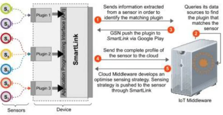
Figure 2-15 - System Architecture of the CADDOT model (Perera, Jayaraman, et al., 2013).
sensors deployed based on a specific location despite their heterogeneity (for example, different communication protocols, communication sequences and capabilities).
The system architecture presented above is composed by three main components: the sensors, the SmartLink tool and the cloud middleware. The Smartlink tool presented is just a mediator between the sensors and the middleware, which looks to improve the information exchange, the capability of the network and the system’s organization.
Figure 2-16 - CADDOT Model for Sensor Configuration (Perera, Jayaraman, et al., 2013).
Figure 2-16 depicts the approach of the CADDOT model for sensor configuration, on which the SmartLink tool represents a major role. The SmartLink serves as an open wireless spot, so sensors can connect to it using an ad-hoc approach (Detect), extract information from the sensors detected (Extract), send information related to the new detected sensor to the middleware (Identify), receive plugin information related to the sensor from the middleware (Find), retrieve the sensor’s information with direct communication using the downloaded plugin (Retrieve) and provide the sensor’s full information for registration on the middleware (Register). After that, the stages Reason and Configure are responsible for processing the information of the sensors in order to optimize its functioning.
This system is just an example of this kind of systems and may vary in other models, which usually present different methodologies and purposes.
Other important concepts, more related to the communication itself are: Network Mapping, Network Discovery and Networked Control System. They are frequently referred in models like the one that was mentioned before and are presented here for greater clarification and understanding of the concept of Dynamic Network Communication.
Network Mapping - It is the study of the physical network connectivity. Network Mapping is used to find the devices that belong to the network (or were recently added) and to understand how they communicate. It usually defines the process before Network Discovery, because it only finds the information about what devices are connected to a network and what operative system/configurations they run.
This concept is relevant to this work because by creating an autonomous system, the idea is to read data from the environment and to adapt efficiently. Some common situations that induce this behaviour are not only environment variations but also failures and errors that may occur in the network. By recovering from such situations, the system is truly autonomous. The role of this concept is to understand and monitor the physical components of the network, the devices and connections, in a way that is possible for the network to understand and get feedback from their performance and functioning.
Networked Control System - This type of system is divided into four components:
• Sensors, responsible for retrieving information from the environment;
• Controllers, capable of forwarding commands and decision-making based upon the collected data;
• Actuators, which execute the actions requested by the controllers;
• Communication Network, that allows information exchange.
The most important feature of the Networked Control System (NCS) is the connection between the virtual and physical space, allowing the execution of various tasks remotely and sometimes autonomously. It also reduces the complexity of physical connections and cost in design and system implementation. Some types of communication typically used are Fieldbuses, Ethernet and Wireless (like for example, Bluetooth and ZigBee).
2.4.1 Discussion towards Semantic Maps
Communication plays a major role in a dynamic network, as was mentioned before, due to necessity of constantly respond to the changes monitored in the environment. The advantages of preparing a network, using proper configuration, to be dynamic relatively to the environment where it was deployed far exceed, in most cases, the rigid and specific network configurations, due to the autonomy and adaptation processes needed.
concepts and methodologies contribute to a great part of this work, the creation of semantic maps.
Semantics is the study of meaning (Merriam-Webster, 2017). The items defined by these meanings can be grouped to what is called a semantic field. Thus, the semantic field represents a lexical set of semantically related words that are related due to different aspects such as context, place or activity. The interest that drives the use of this concept in technological environments is the need, as mentioned before, to make information more computer friendly and therefore, provide the context and meaning to the words that the computers lack to have internal representation of.
Figure 2-17 - Example of Relations (Paiva, 2015).
Therefore, semantic mapping can be viewed as a strategy to represent concepts or technological instances. The semantic maps that result from the process are relations of a certain concept, by the definition of semantics. Some basic relations in semantics are shown in Figure 2-17 and they represent the basis for associating concepts and meanings. There can be different associations for any concept, like associations of class (the order of things the concept falls into), property (the attributes that define the concept) or example (examples of the concept) (Estes, 1999). In technology, since the internal representation of information gathered by technological components is not intuitively understandable by humans and vice-versa and it is also inadequate for fast learning processes, the combination of object classification and common-sense knowledge with semantic maps, represents an interesting approach to provide this type of information.
3
Semantic Mapping
In this chapter, the architecture for the module developed in this dissertation is presented. The first section is an overview of the contents of this module, the second section delivers a description of the main concepts that originated and provided basis for this work. After that, the architecture is explored, and the contents of each module are explained. The last section contextualizes the project in an application scenario that briefly shows the possibilities for the developed solution.
3.1
Overview
Generally, systems that rely on processing the information of deployed devices and their analysis, to read or predict conditions that could trigger pre-determined rules, recur to the integration of a Complex Event Processing module. A Complex Event Processing (CEP) module analyses large flows of primitive events received from a monitored environment to timely detect situations of interest (Margara, Cugola, & Tamburrelli, 2014). This processing takes place following user-defined rules and that aspect induces a liability to the dynamism of the general system, because any change may cause an incompatibility to adapt or, in the case of a device failure, the rules may become obsolete due to a non-implementation of redundancy.
Figure 3-1 - CEP Generic Concept.
pre-determined rules (created by the developer), detects situations that may trigger events on the devices or simply alerts the system monitor.
The idea behind understanding the CEP is to perceive its importance in the application of the models studied in chapter 2, and to provide the intended methodology that this dissertation aims to propose, the use of semantic maps. These semantic maps, as mentioned before, are intended to improve and test the trustworthiness of the system by standing as a tool to overcome errors and failures in devices or, more specifically, in sensors. The idea for the functioning method of these maps is to be a representation of similar configurations for the sensors, therefore an alternative mapping for the CEP module to listen to the network of devices and retrieve the information needed to use the existing rules.
Recurring to a brief example, let’s say that the sensor A is damaged by unknown
reasons and provides unusable information (for example, absurdly high temperature readings), as depicted in Figure 3-2. Disregarding the detection of such failure, that will be mentioned further in this chapter, the sensor A stands as a liability to the event processing and may cause several rules to become obsolete for not having the necessary information to be triggered. In this way, the system is prone to fail to comply to the initial expectations for its correct functioning. To tackle this situation, usually, human interaction is needed to provide a solution for this problem. An implementation of another temperature sensor or the use of a temperature sensor that is already present in the network are options that the system monitor may find to solve this problem. In large networks, in industrial environments, there are numerous sensors, deployed for many different uses. So, regarding that aspect, it makes sense to believe that using other sensors to solve this problem is a possible and common solution.
Figure 3-2 - Example of Detection of a Sensor Failure.
Figure 3-3 - Example of Solution to a Sensor Failure.
In Figure 3-3, it is depicted that the Sensor B provided a redundancy to the sensor A. This is a very simple solution, but is not automated in any way, that means that requires human intervention and lacks autonomous dynamic adaptation.
Other example of failure is depicted in Figure 3-4, in this case, the method to detect the failure or malfunctioning is inconsistency by proximity comparison, a fault detection method to be exploited in chapters 4 and 5.
Figure 3-4 Example of Sensor Malfunctioning.