148 Micro and Nanosystems, 2015, 7, 148-153
Blood Flow Visualization and Measurements in Microfluidic Devices
Fabricated by a Micromilling Technique
Jaron Singhal
1, Diana Pinho
2,3,*, Raquel Lopes
2, Patricia C. Sousa
3, Valdemar Garcia
2,
Helmut Schütte
1, Rui Lima
2,3,4and Stefan Gassmann
11
Jade University of Applied Science, Wilhelmshaven, Germany.2ESTiG, Polytechnic Institute of Bra-gança (IPB), Portugal. 3CEFT, Faculdade de Engenharia da Universidade do Porto (FEUP), Portu-gal. 4Mechanical Eng. Dep., University of Minho, Campus de Azurém, 4800-058 Guimarães, Portugal
Abstract: The most common and used technique to produce microfluidic devices for biomedical ap-plications is the soft-lithography. However, this is a high cost and time-consuming technique. Re-cently, manufacturers were able to produce milling tools smaller than 100 m and consequently have promoted the ability of the micromilling machines to fabricate microfluidic devices capable of per-forming cell separation. In this work, we show the ability of a micromilling machine to manufacture microchannels down to 30 m and also the ability of a microfluidic device to perform partial separa-tion of red blood cells from plasma. Flow visualizasepara-tion and measurements were performed by using a high-speed video microscopy system. Advantages and limitations of the micromilling fabrication proc-ess are also presented.
Keywords: Biomedical applications, blood cells, cell-free layer, cells separation, micromilling, microfluidic devices.
1. INTRODUCTION
In the field of blood analysis miniaturization, blood cells separation in microfluidic devices become an indispensable factor. In blood analysis and diagnosis, the main attention is directed towards the red blood cells (RBCs), since they exist in blood in a high concentration (typically in the range of 38-46% in women and 42-53% in men [1]) and also because they carry important information about the human’s medical condition. For that reason, a lot of methods have been devel-oped, to separate the RBCsand or white blood cells (WBCs) from the bulk blood [2-9]. To obtain a cell separation at a microfluidic level, special channel geometries have to be integrated within the microfluidic system, Fujiwara et al. [3] and Leble et al. [4] have found evidence that it is possible to create an artificial cell-free layer (CFL) in different kinds of microfluidic geometries, such as, constrictions and conflu-ences. These in vitro studies are performed with the most popular and traditional method to fabricate microfluidic de-vices, the soft lithography technique, employing polydi-methylsiloxane (PDMS) elastomer microchannels. By using this fabrication technique, several researchers [5-7, 9] have demonstrated that the CFL could be enhanced by using a microchannel containing a constriction followed by sudden expansion to separate plasma from the whole in vitro blood. However, the SU-8 moulds used for this method need to be fabricated by photolithography in a clean room environment with specialized equipment. For instance, a mask aligner is
*Address correspondence to this author at the Department of Mechanical Technology, ESTiG-IPB, Braganca, Portugal; Tel: +351 273 30 31 91; Fax: 273 31 30 51; E-mail: [email protected]
needed for the fabrication of the masks, which are used to produce the SU-8 moulds and corresponding PDMS devices.
The acquisition of these moulds becomes very costly and time-consuming especially, for facilities without the possibil-ity to perform photolithography. The high costs and time-consuming involved in the traditional photolithography process are currently slowing down the interest of the indus-trial community to commercialize this kind of microfluidic devices for engineering and biomedical applications. Hence, it is crucial to develop simple, rapid and low-cost nonlitho-graphic techniques to fabricate microfluidic systems.
Recently, several researchers have demonstrated that it is possible to perform cell separation by using low-cost tech-niques to fabricate microfluidic systems. Recently, Pinto et al. [10] have used a print-and-peel (PAP) method, known as xurography to perform blood flow studies in bifurcations and confluences. This method has shown to be an effective, novel, and rapid prototyping technique to fabricate microflu-idic channels [11]. However, with this method it was not possible to fabricate microchannels less than 100 m width and as a result blood flow studies were limited to geometries bigger than 100 m. Other low cost techniques such as xero-graphic [12], laser jet printer [13], 3D rapid prototyping technology [14] have demonstrated the ability to produce functional molds for PDMS microfluidic microdevices. Ad-ditional microfabrication methods that do not require the use of cleanrooms can be found in recent reviews performed by Rodrigues et al. [15] and Faustino et al. [16].
In this work, a nonlithographic technique is used to fabri-cate microchannels. A convenient option to soft-lithography is micromilling in acrylic glass (polymethyl methacrylate,
PMMA). Recently, milling tools down to a diameter of 5 m have consequently promoted the ability of milling machines to fabricate microchannels smaller than 100 m without a clean-room facility. This technology provides a rapid pro-duction of microchannels with various geometries from the idea to the design and to the fabrication. Here, we show the ability of a micromilling machine to manufacture micro-channels with geometries down to 30 m. A straight contrac-tion geometry was used in the middle of the main channel, to promote the formation of CFL adjacent to the channel walls [3, 5-7]. Under special circumstances, like the properties of the blood sample and the dimensions of the channel geo-metries, the RBCs tend to migrate towards the center of the channel [17-21], surrounded by a plasma layer. The thick-ness of this layer depends on various factors, i.e., hematocrit (Hct) [18, 20, 21], flow dynamics [5, 6], working fluid [17-21] and geometry of the microchannel [3-9].
The proposed geometries used in this work, have a sud-den contraction to increase the CFL formation downstream and we have measured the CFL thickness at different condi-tions for two different geometries.
2. MATERIALS AND METHODS
2.1. Fabrication of the Microfluidic Device
The microfluidic devices tested in this study were fabri-cated by using a micromilling machine built for micro-machining (Minitech Mini-Mill/GX). Channels were fabri-cated with a rectangular section inlet, 300 m in width and 40-60 m in depth, a contraction 30 m long and two out-lets. The main function of the geometries is to promote cell separation as efficient as possible using the CFL formation downstream of the contraction. Therefore, the channels are provided with narrow contractions, since previous experi-ments have shown that this method supports the formation of the CFL [3, 5-7]. The outlets of the channel are arranged in such way that the high concentration of RBCs should flow to Outlet 1 and the lower hematocrit should flow to Outlet 2. Fig. (1) shows an example of the fabricated channels.
Before starting the fabrication process, the geometries of the channels have to be considered, according to the metrics as well as the effect that has to be obtained and the feasibility of the fabrication has to be estimated, concerning to the limita-tions of the milling tools. In this work, milling tools with the diameters of 30 m and 100 m were used. In a CAD-Software geometries with defined metrics can be designed by drawing the outlines of each structure to be milled. To create the NC-code, which is readable for the milling machine, a .dxf-file containing the designed geometries is opened in VisualMill, a milling software module. By using this software several fabrication parameters, such as total cut depth, rough depth, speed and tolerance can be selected for each milling part. Note that, all parameters have to be adjusted for each milling tool used, since they have different properties, like height or fragility. The software used in this work calculates the path of the milling machine and creates a numerical code, saved in a .nc-file.
After placing the work piece on the vacuum table, the ta-ble can be adjusted by defining the reference points with the Minitech software, which provides the controlling of the
machine. Special attention has to be taken for the z-axis con-trol. The milling machine has no height control to determine the top point of the milled material. This point, which is the reference point (z = 0) for the milled structure has to be found manually. For this the milling tool has to be set in ro-tation and lowered to the material in 1 m increments. With the help of a magnifying camera, the first touch of the mill-ing tool on the material can be observed. This process has to be repeated for each milling tool and needs to be changed manually. During the milling process, the work piece and the tool have to be cooled by a mixture of water and detergent. Otherwise, the heat resulting from the high rotation speed can damage the milling tool and the milled channels. After finishing the milling process and cleaning the device with water and detergent, the depth of the microchannels can be measured by means of a 3D optical profiler using confocal and interferometric principle (Sensofar, plu neox) [22].
The in/outlets are made of stainless steel tubes with a di-ameter of approximately 1 mm and length of 1 cm. To obtain a better adhesion of the material, the surface around the in/outlets and the tubes can be treated by argon-plasma be-fore adding the epoxy glue. After the curing of the glue, the device has to be cleaned in an ultrasonic bath to remove the remaining particles from the channels and also to clean the surface. Finally, the channels, Fig. (1), can be dried and sealed with an adhesive foil.
Fig. (1). Photograph of the PMMA wafer fabricated by a mi-cromilling machine with microchannels sealed with an adhesive film and detailed optical micrograph of the contraction region.
2.2. Working Fluid and Experimental Set-Up
Blood was taken from a healthy sheep and EDTA had to be added to prevent coagulation of the blood cells. By cen-trifugation, the RBCs were extracted from the bulk blood and washed twice with saline solution. Dextran 40 (Dx40), a solution with flow properties similar to blood plasma, was used for preparing samples of 2.5 and 5 (v/v) % of Hct. All blood samples were stored hermetically at 4 ºC until the ex-periments were performed at room temperature of approxi-mately 20 ºC.
Fig. (2). High-speed video microscopy system used to perform
experimental in vitro blood studies.
2.3. Image Analysis
In order to visualize the CFL formation in the micro-channel, the images were captured around the middle of the microchannels with a resolution of 10241024 pixels, at a rate of 2000 frames/s. Then, all videos were evaluated using a manual image analysis by using the plugin MtrackJ [23, 24], from the software ImageJ (NIH) [25].
The CFL thickness measurements were performed by ob-taining the trajectories of the RBCs flowing around the CFL boundary and subtracting them with the reference coordi-nates of the walls. Moreover, the coordicoordi-nates resulting from these tracking’s were used to determine the average thick-ness of the CFL (see Fig. 3). Based on the acquired data, in the form of coordinates, and according to the geometries and the flow rate, the average thickness of the CFL was evalu-ated.
Fig. (3). Recorded experimental image showing the tracking at the channel wall and RBCs flowing around the CFL boundary. The difference between the two positions can be used to calculate the CFL thickness.
3. RESULTS AND DISCUSSION
3.1. Fabrication Evaluation
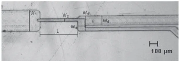
The microfluidic devices tested in this study consisted of two microchannels with aprojectedinlet with 300 m of width upstream the contraction. The length (L) of the con-traction differs between the channels. Downstream of the sudden contraction of the microchannels has difference in the depths of the outlets. Fig. (4) shows the relevant vari-ables of the microchannel and in Table 1 we present the cor-responding dimensions.
Fig. (4). A schematic illustration of the main dimensions of the tested devices.
Table 1. Main dimensions of the tested microfluidic devices.
Device 1 (m) Device 2 (m)
W1 305 305
L 1450 515
W2 30 30
W3 300 300
W4 205 205
W5 130 130
The depths of the channels were measured by using a 3D optical profiler (Sendofar, PLu neox). The measurements obtained by this profiler are presented in Fig. (5). The results have shown that the depth of Device 1, Fig. 5a), at the con-traction region was 50 m and was constant for the two out-lets. In contrast, the depth of Device 2 was not uniform as the depth at the contraction and outlet 2 was 40 m and at the outlet 1 the depth was 68 m, Fig. 5b).
The accuracy of the fabrication, considering the original two dimensional drawing performed in the CAD Software, the real dimensions were in close agreement with the ex-pected 2D dimensions, since the difference between both dimensions is ± 5 m. However, it is possible to observe that the depth of the Device 2 (Fig. 5b)) is not uniform along the full length of the microchannel. Hence, the procedure to con-trol the z-axis (height) is one of the main difficulties and challenges of this technique. More detailed information about the micromilling fabrication process can be found at Lopes et al. [26].
3.2. Blood Flow Visualization
Due to the high speed camera that was attached to the in-verted microscope, the motion of the blood cells could be recorded with a high enough quality resolution to perform tracking measurements of individual RBCs. In this section the results of the flow visualizations are presented and dis-cussed.
For the two tested devices in this study, the CFL thick-ness was measured for six different flow rates with a work-ing fluid of 2.5 % Hct. In this work, the results obtained downstream of the contraction since in the upstream part have been analyzed, only a residual formation of the CFL was observed, as shown in the Fig. (6).
CFL up
Fig. (5). Depth measurements from a 3D optical profiler: a) in Device 1 the depth is uniform and is about 50 m; b) in Device 2 the depth of the contraction and outlet 2 is 40 m whereas the depth of the outlet 1 is 68 m.
Fig. (6). In vitro blood flowing a) upstream of the contraction where there is negligible CFL; b) downstream of the contraction where there is a clear CFL.
From Fig. (7) and for the case of the Device 1, it is possi-ble to observe that the upper CFL thickness is bigger than 20 m and the down CFL has a thickness higher than 10 m. These results show clearly that, for this particular device, the CFL thickness is asymmetric. Additionally, by increasing the flow rate, the CFL thickness slowly increases until reaching a constant value.
The ultimate purpose of this work is to obtain a full sepa-ration of RBCs from plasma. However by using the Device 1, some amount of RBCs still flow through the outlet 2. Note that, a full separation will be obtained if all RBCs follow through the outlet 1. In order to improve the separation effi-ciency a new microfluidic device (Device 2) was fabricated. In this new device, we have decided to reduce the contrac-tion length. However, due to the difficulty of controlling the z-axis the depth of this latter device was not uniform and different from the depth measured at the Device 2. Neverthe-less, we have decided to perform in vitro blood flow meas-urements with the Device 2.
Fig. (7). CFL thickness downstream of the contraction for the De-vice 1. Error bars shows a 95 % of confidence interval.
The results from Fig. (8), show that by reducing the con-traction length, the CFL at the upper part decreases signifi-cantly. Hence, by using this device the CFL thickness tends to have a performance more close to a symmetric behaviour. The reduction of the contraction length might be the main reason for this observed phenomenon as similar results were also observed in microfluidic devices fabricated by a soft-litography technique [5, 26]. However, in our study the in-crement of the depth at the outlet 1 may also have played an important role in the encountered phenomenon. Although, Device 2 may be more efficient regarding the blood separa-tion efficiency, further research needs to be performed in the near future. Note that, by increasing the flow rate, the CFL thickness has shown a similar tendency as the one observed in the Device 1.
Fig. (8). CFL thickness downstream of the contraction for the De-vice 2. Error bars represents a 95 % confidence interval.
a) b)
0 5 10 15 20 25
1 5 10 15 25 35
CFL thickness
(µm)
Q (µL/min)
CFL upper CFL down
0 5 10 15 20 25
1 5 10 15 25 35
CFL thickness
(µm)
Q (µL/min)
CFL upper
For the particular case of the Device 2 in vitro blood flow measurements were also performed by using a working fluid with a Hct of 5 %. The results from Fig. (9) show that the CFL thickness tends to decrease by increasing the Hct. These results are in close agreement with past experimental studies [5-9]. Hence, in future work, it is crucial to take into account this last phenomenon when designing a new geometry.
Fig. (9). CFL thickness downstream of the contraction for Device 2 at 2.5 % and 5 % hematocrit. Error bars represents a 95 % confi-dence interval.
3.3. Potential Benefits and Limitations
Soft-lithography is the most common technique to fabri-cate microfluidic devices used in bioengineering and bio-medical engineering. However, this technique due to the necessity of cleanrooms that increase the fabrication cost, the long time from the design to the prototype and inaccessible techniques to most biologists are slowing down the interest of the biomedical community to use this kind of devices.
In this work we have demonstrated that micromilling is a promising alternative technology to soft-lithography as low-cost microfluidic devices were developed. Overall, the re-sults obtained from the devices produced by the mi-cromilling technique were extremely encouraging, due to its fast fabrication time, independence from clean room facili-ties and ability to produce microchannels smaller than 100 m. Hence, this technique is a promising solution to manu-facture affordable microfluidic devices to work in the scales required to perform blood cell analysis in continuous flow.
During our experimental activities we have observed that the produced microchannels can be used several times creat-ing the possibility of reproduccreat-ing the results. Another advan-tage of this technology is that the blood cells did not attached to the walls and as a result we did not observed clogging and jamming of the microchannel. However, by using PMMA we produce a microfluidic system with rigid walls, so im-provements need to be done in order to have a device mim-icking the in vivo environment.
Although micromilling looks promising, there are several disadvantages associated with this technique such as com-plex tool alignment, easily tool breakage and the roughness of the channel walls.
CONCLUSIONS AND FUTURE WORK
Two microfluidic devices were fabricated by a low cost technique known as micro-milling. Blood flow visualization
and measurements of the CFL thickness were performed and parameters, such as geometry and Hct, were studied. Also, their influence in the CFL formation downstream of a con-traction with a width of 30 m was analyzed. The results have demonstrated that the presence of a small contraction has promoted an improvement in the separation of the RBCs from plasma. Additionally, the results have shown that the
Hct affects the separation efficiency as the CFL thickness decreases with increasing Hct.
The contraction length and the depth at the downstream part of the contraction may play an important role in the blood separation efficiency. Hence, in future work, it is im-portant to take into account these two parameters to achieve a microfluidic device able to perform a full separation of blood cells from plasma. Overall, the results are in good agreement with studies performed in microchannels obtained by high cost fabrication techniques [5-7, 9]. Therefore, the micromilling technique shows potential to fabricate low cost microfluidic devices able to perform blood flow studies without the use of expensive facilities such as clean-room environments
CONFLICT OF INTEREST
The authors confirm that this article content has no con-flict of interest.
ACKNOWLEDGEMENTS
The authors acknowledge the financial support provided by PTDC/SAU-ENB/116929/2010 and EXPL/EMS-SIS/ 2215/2013 from FCT (Science and Technology Foundation), COMPETE, QREN and European Union (FEDER). DP ac-knowledge the PhD scholarship SFRH/BD/89077/2012, and P.C. Sousa acknowledges the fellowship SFRH/BPD/75258/ 2010, all attributed by FCT.
REFERENCES
[1] Thiriet, M. Biology and mechanics of blood flows. Springer, 2008, New York.
[2] Rodrigues, R.O.; Pinho, D.; Faustino, V.; Lima, R. A simple micro-fluidic device for the deformability assessment of blood cells in a continuous flow. Biomed. Microdevices,2015,17(6), 108. [3] Fujiwara, H.; Ishikawa, T.; Lima, R. Red blood cell motions in
high-hematocrit blood flowing through a stenosed microchannel. J.
Biomech.,2009, 42, 838-843.
[4] Leble, V.; Lima, R.; Dias, R.; Fernandes, C.; Ishikawa, T.; Imai, Y.; Yamaguchi, T. Asymmetry of red blood cell motions in a mi-crochannel with a diverging and converging bifurcation. Biomicro-fluidics,2011,5, 044120.
[5] Faivre, M.; Abkarian, M.; Bickraj, K. Stone HA Geometrical fo-cusing of cells in a microfluidic device: An approach to separate blood plasma. Biorheology,2006,43, 147-159.
[6] Sollier, E.; Cubizolles, M.; Fouillet, Y.; Achard, J.L. Fast and con-tinuous plasma extraction from whole human blood based on ex-panding cell-free layer devices. Biomed. Microdevices,2010,12 485-497.
[7] Pinho, D.; Yaginuma, T.; Lima, R. A microfluidic device for partial cell separation and deformability assessment. BioChip J., 2013, 7(4), 367-374.
[8] Lima, R.; Wada, S.; Tanaka, S, Takeda M, Ishikawa T, Tsubota K, Imai Y, Yamaguchi T. In vitro blood flow in a rectangular pdms microchannel: Experimental observations using a confocal micro-piv system. Biomed. Microdevices,2008,10, 153-167.
[9] Yaginuma, T.; Oliveira, M.S.; Lima, R.; Ishikawa, T.; Yamaguchi, T. Human red blood cell behavior under homogeneous extensional
0 5 10 15 20 25
1 5 10 15 25 35
CFL thickness
(µm)
Q (µL/min)
flow in a hyperbolic-shaped microchannel. Biomicrofluidics,2013, 7, 54110.
[10] Pinto, E.; Faustino, V.; Rodrigues, R.O.; Pinho, D.; Garcia, V.; Miranda, J.M.; Lima, R. A Rapid and Low-Cost Nonlithographic Method to Fabricate Biomedical Microdevices for Blood Flow Analysis. Micromachines,2015,6, 121-135.
[11] Bartholomeusz, D.A.; Boutte, R.W.; Andrade, J.D. Xurography: Rapid prototyping of microstructures using a cutting plotter. J.
Mi-croelectromech. Syst.,2005,14, 1364-1374.
[12] Tan, A.; Rodgers, K.; Murrihy, J.; O’Mathuna, C.; Glennon, J.D. Rapid fabrication of microfluidic devices in poly(dimethylsiloxane) by photocopying. Lab Chip,2001,1, 7-9.
[13] Branham, M.L.; Tran-Son-Tay, R.; Schoonover, C.; Davis, P.S.; Allen, S.D.; Shyy, W. Rapid prototyping of micropatterned sub-strates using conventional laser printers. J. Mater. Res.,2002,17, 1559-1562.
[14] Bonyár, A.; Sántha, H.; Ring, B.; Varga, M.; Gábor Kovács, J.; Harsányi, G. 3D rapid prototyping technology (rpt) as a powerful tool in microfluidic development. Procedia Eng.2010,5, 291-294. [15] Rodrigues, R.O.; Lima, R.; Gomes, HT.; Silva, A.M.T. Polymer
microfluidic devices: an overview of fabrication methods. U. Porto J. Eng.,2015,1(1), 67-67.
[16] Faustino, V.; Catarino, S.O.; Lima, R.; Minas, G. Biomedical mi-crofluidic devices by using low-cost fabrication techniques: a re-view. J. Biomech.,2016 (in press).
[17] Calejo, J.; Pinho, D.; Galindo-Rosales, F.J.; Lima, R.; Campo-Deaño, L. Particulate blood analogues reproducing the erythrocytes cell-free layer in a microfluidic device containing a hyperbolic con-traction. Micromachines,2016,7, 4.
[18] Maeda, N.; Suzuki, Y.; Tanaka, J.; Tateishi, N. Erythrocyte flow and elasticity of microvessels evaluated by marginal cell-free layer and flow resistance. Am. J. Physiol.,1996,271, 2454-2461.
[19] Lima, R.; Ishikawa, T.; Imai, Y.; Yamaguchi, T. Blood flow behav-ior in microchannels: advances and future trends. In: Ricardo D.M, Rui L, Antonio A, Teresa M.M. Eds.; Single and two-phase flows on chemical and biomedical engineering. Bentham Sci.,2012, pp 513-547.
[20] Kim, S.; Ong, P.K.; Yalcin, O.; Intaglietta, M.; Johnson, P.C. The cell-free layer in microvascular blood flow. Biorheology,2009,46, 181-189.
[21] Garcia, V.; Dias, R.; Lima, R. In Vitro Blood Flow Behaviour in Microchannels with Simple and Complex Geometries, In: Naik, G.R. Ed.; Applied Biological Engineering - Principles and Practice. 2012, InTech, pp. 393-416.
[22] Lopes, R.; Rodrigues, R.O.; Pinho, D.; Garcia, V.; Schutte, H.; Lima, R.; Gassmann, S. Low cost microfluidic device for partial cell separation: micromilling approach. in Proceedings of 2015 IEEE International Conference on Industrial Technology, Seville, Spain.
[23] Meijering, E.; Smal, I.; Danuser, G. Tracking in molecular bioi-maging. IEEE Signal Process Mag.,2006,23, 46-53.
[24] Pinho, D.; Gayubo, F.; Pereira, A.I.; Lima, R. A comparison be-tween a manual and automatic method to characterize red blood cell trajectories. Int. J. Num Methods Biomed. Eng.,2013, 29(9), 977-987.
[25] Abramoff, M.D.; Magalhaes, P.J.; Ram, S.J. Image Processing with ImageJ. Biophotonics Int.,2004,11, 36-42.
[26] Rodrigues, R.O.; Lopes, R.; Pinho, D.; Pereira, A.I.; Garcia, V.; Gassmann, S.; Sousa, P.C.; Lima, R. In Vitro Blood Flow and Cell-Free Layer in Hyperbolic Microchannels: Visualizations and Measurements. BioChip J.,2016 [Epub ahead of Print].