FREDERICO CARNEVALLI DE MIRANDA
PRELIMINARY DESIGN OF AN EXPERIMENTAL
BIPLANE AIRCRAFT, BIPLANE CANARD AND
PUSHER THRUST, FOR TWO OCCUPANTS IN
TANDEM
UNIVERSIDADE FEDERAL DE UBERLÂNDIA
FACULDADE DE ENGENHARIA MECÂNICA
FREDERICO CARNEVALLI DE MIRANDA
PRELIMINARY DESIGN OF AN EXPERIMENTAL BIPLANE AIRCRAFT,
BIPLANE CANARD AND PUSHER THRUST, FOR TWO OCCUPANTS IN
TANDEM
Undergraduate thesis submitted to the Course of Aeronautical Engineering from the Federal University of Uberlândia as a part of requirement for obtaining the BACHELORS DEGREE ON AERONAUTICAL ENGINEERING.
Tutor: Prof. Dr. Odenir de Almeida
UBERLÂNDIA
–
MG
FREDERICO CARNEVALLI DE MIRANDA
PRELIMINARY DESIGN OF AN EXPERIMENTAL BIPLANE AIRCRAFT,
BIPLANE CANARD AND PUSHER THRUST, FOR TWO OCCUPANTS IN
TANDEM
Undergraduate thesis APROVED by the Course of Aeronautical Engineering from the Faculty of Mechanical Engineering of the Federal University of Uberlândia.
Thesis Committee Composition:
__________________________________________ Prof. Dr Odenir de Almeida
__________________________________________ Prof. Msc Giuliano Gardolinski Venson
__________________________________________ Prof. Dr Thiago Augusto Machado Guimarães
ACKNOLEGEMENTS
To undergraduate in aeronautical engineering and to design a new airplane always was a dream that I was able to perform with the help of the Federal University of Uberlândia (UFU), so I would like to thank all the staff of masters that supplied me with the necessary technical knowledge to realize this work.
MIRANDA, F. C. Preliminary Design of an Experimental Biplane Aircraft, Biplane Canard and Pusher Thrust, for two Occupants in Tandem. 2017. 443 f. Projeto de Conclusão de Curso, Universidade Federal de Uberlândia, Uberlândia.
RESUMO
A concepção e desenvolvimento de uma nova aeronave é naturalmente uma atividade multidisciplinar envolvendo tecnologias relacionadas à aerodinâmica, estruturas e diversas outras relacionadas aos diversos sistemas sejam eles mecânicos, elétricos, eletrônicos entre outros. Dessa característica resulta uma sequência de trabalho extremamente complexa. Quando a aeronave em questão é caracterizada por uma configuração extremamente peculiar e para a qual as fontes de referência técnica são bastante limitadas, esse trabalho se torna ainda mais desafiador e complexo, já nas fases iniciais de concepção essas dificuldades foram sentidas. As atividades relacionadas ao projeto preliminar tiveram como ponto de partida a ergonomia do “cockpit”, adotando a filosofia de projeto de dentro para fora. À medida que as tarefas de engenharia se desenvolviam e considerando as características particulares da aeronave, modificações na teoria existente e proposições de novas abordagens surgiram inevitavelmente, uma vez que a teoria disponível na literatura se mostrou limitada. Conforme os resultados relacionados à aerodinâmica foram sendo obtidos verificou-se que o desempenho da aeronave com relação às velocidades de voo superou em muito os valores inicialmente assumidos para a operação da mesma. Com respeito às características de controle os resultados obtidos podem ser considerados bastante satisfatórios, exceto aqueles relacionados com a corrida de decolagem devido à pouca eficiência dos “canards” nessa fase do voo. Com relação à estabilidade os resultados indicam que a aeronave está com comportamento marginalmente positivo em alguns aspectos e marginalmente negativo em outros aspectos.1
MIRANDA, F. C. Preliminary Design of an Experimental Biplane Aircraft, Biplane Canard and Pusher Thrust, for two Occupants in Tandem. 2017. 443 f. Projeto de Conclusão de Curso, Universidade Federal de Uberlândia, Uberlândia.
ABSTRACT
The conception and development of a new aircraft is naturally a multidisciplinary activity that involves technologies related to the aerodynamics, structures, and technologies related to several systems as mechanical, electrical, electronic among others. Due this characteristic, was resulted an extremely complex sequence of work. When the aircraft to be developed is characterized by a very peculiar configuration and for which the sources of technical reference are quite limited, this work turn even more challenger and complex, already in the earlier conceptual phases these difficulties were faced. The activities related to the preliminary design had as start point the ergonomics of the cockpit, adopting for the aircraft the design philosophy from the inside to the outside. As the engineering activities were developed and considering the particular characteristics of the aircraft, were proposed modifications on the existing theory and new theory approach necessarily emerged, once the available theory on the bibliography proved insufficient. As the results related to the aerodynamics were being obtained, was verified that the performance relative to the flight speeds far exceeded the values initially defined for the operation of the aircraft. With respect to the in flight control characteristics, the results obtained may be considered very satisfactory, except that related to the take-off runway rolling due the few canards efficiency. With respect to the stability behavior the results indicate that the aircraft is marginally positive in some aspects and is marginally negative relative to other aspects.2
LIST OF FIGURES
Figure 1.1 - 14Bis flight on October 23th, 1906. (Available in:
<https://www.google.com.br/search?q=14bis&tbm=isch&tbo=u&source=univ&sa=X&ved=0a
hUKEwic5f-T6NfWAhXFFpAKHas-B2kQsAQIQA&biw=1366&bih=651>. Access in
november 11, 2017) ... 7
Figure 1.2 - Airplane UFU-1 initial sketch. ... 7
Figure 1.3 - Airplane UFU-1 initial sketch. ... 8
Figure 1.4 - Airplane UFU-1 final drawing. ... 9
Figure 1.5 - 14bis at flight. (Available in: <https://www.google.com.br/search?q=14bis&tbm=isch&tbo=u&source=univ&sa=X&ved=0a hUKEwic5f-T6NfWAhXFFpAKHas-B2kQsAQIQA&biw=1366&bih=651>. Access in november 11, 2017) ... 10
Figure 1.6 - Wright brothers’s Flyer I. (Available in: <https://www.google.com.br/search?biw=1366&bih=651&tbm=isch&sa=1&q=FLYER+I+WR ITE+BROTHERS&oq=FLYER+I+WRITE+BROTHERS&gs_l=psy- ab.3...185598.208467.0.209760.30.27.2.0.0.0.428.3789.2j16j4j0j1.23.0....0...1.1.64.psy-ab..6.9.1538...0j0i67k1.0.OHOkrI57P7A#imgrc=_&spf=1507149400162>. Access in november 11, 2017) ... 10
Figure 1.7 - Red baron airplane, Fokker Dr.I. (Available in: <https://www.google.com.br/search?q=bar%C3%A3o+vermelho+avi%C3%A3o&tbm=isch&t bo=u&source=univ&sa=X&ved=0ahUKEwi9ksj169fWAhUCP5AKHTZIAIIQsAQIRA&biw=13 66&bih=651#imgrc=_&spf=1507150197293>. Access in november 11, 2017) ... 11
Figure 1.8 - Airplane Spad 13, first great war. (Available in: <https://www.google.com.br/search?q=Airplane+Spad+13&tbm=isch&tbo=u&source=univ& sa=X&ved=0ahUKEwicsYP87NfWAhXDE5AKHbaHCMYQsAQIQA&biw=1366&bih=651#im grc=_&spf=1507150916189>. Access in november 11, 2017) ... 11
Figure 1.9 - Airliner Fokker F-10, from 1927. (Available in: <https://en.wikipedia.org/wiki/Fokker_F.10>. Access in november 11, 2017) ... 12
Figure 1.11 - North American XB-70 Valkyrie, before first flight on September 21th, 1964.
(Available in: <https://en.wikipedia.org/wiki/North_American_XB-70_Valkyrie>. Access in
november 11, 2017) ... 13
Figure 1.12 - Beechcraft Starship, executive airplane. (Available in: <https://en.wikipedia.org/wiki/Beechcraft_Starship>. Access in november 11, 2017) ... 13
Figure 2.1 - Wings with various taper ratios: (a) Rectangle (λ = 1); (b) Trapezoid 0 < λ < 1 ... 16
Figure 2.2 - Mean aerodynamic chord (Raymer, 2006). ... 17
Figure 2.3 - Five wings with different sweep angles (Sadraey, 2013). ... 17
Figure 2.4 - Dihedral and anhedral angles (Sadraey, 2013). ... 18
Figure 2.5 - Oswald factor for straight and trapezoidal wings (After Venson, 2015). ... 23
Figure 2.6 - Typical mission profile for a civil airplane. ... 25
Figure 2.7 - Generic Payload-Range Diagram. ... 35
Figure 2.8 - Tail sizing geometric scheme (Raymer, 2006). ... 37
Figure 2.9 - Weight-CG envelope.... 43
Figure 2.10 - Height variation for male and female and for different ethnic (Sadraey, 2013). .... 45
Figure 2.11 - Linear body dimensions (cm) (Sadraey, 2013). ... 45
Figure 2.12 - Dimensions for a cockpit of a light aircraft with stick control (Torenbeek, 1976). .. 46
Figure 2.13 - Dimensions for a cockpit of a fighter aircraft (Sadraey, 2013). ... 46
Figure 2.14 - Airfoil lift curve slope (Sadraey, 2013). ... 48
Figure 2.15 - Plain flap geometry(Roskam, 2000). ... 50
Figure 2.16 - Lift effectiveness of a plain flap (Roskam, 2000). ... 50
Figure 2.17 - Correction factor for nonlinear lift behavior of a plain flap (Roskam, 2000). ... 51
Figure 2.18 - Correction factor for plain flap lift (Roskam, 2000). ... 51
Figure 2.19 - Basic airfoil maximum lift increment due to trailing edge flap (Roskam, 2000). .... 52
Figure 2.20 - Flap chord correction factor (Roskam, 2000). ... 53
Figure 2.21 - Flap angle correction factor (Roskam, 2000).... 53
Figure 2.22 - Flap motion correction factor (Roskam, 2000). ... 54
Figure 2.23 - Biplane interference factor (Raymer, 2006). ... 57
Figure 2.24 - Positive and negative stagger representation (Rodrigues, 2011). ... 59
Figure 2.25 - Effect of taper ratio and flap span to wing span ratio on 𝑘𝑏 (Roskam, 2000). ... 62
Figure 2.26 - Effect of aspect ratio and flap chord ratio on the three dimensional flap effectiveness (Roskam, 2000). ... 63
Figure 2.28 - Effect of sweep on planform correction factor (Roskam, 2000). ... 64
Figure 2.29 - Control surface effectiveness parameter (Sadraey, 2013).... 66
Figure 2.30 - Wing fuselage interference factor (Roskam and Lan, 1997). ... 70
Figure 2.31 - Lifting surface correction factor (Roskam and Lan, 1997). ... 70
Figure 2.32 - Turbulent mean skin friction coefficient (After Roskam and Lan, 1997). ... 71
Figure 2.33 - Airfoil thickness location parameter (Roskam and Lan, 1997). ... 72
Figure 2.34 - Ratio of drag coefficient of a circular cylinder in function of the body fineness (Roskam, 2000). ... 75
Figure 2.35 - Steady state cross-flow drag coefficient for two-dimensional circular cylinder (Roskam, 2000). ... 75
Figure 2.36 - Downwash and upwash fields (Brandt). ... 77
Figure 2.37 - Parameters for downwash and upwash prediction (Brandt). ... 77
Figure 2.38 - Sidewash due the wing (Nelson, 1998). ... 79
Figure 2.39 - Fuselage division for wing aerodynamic center shift estimative (Roskam, 2000). 83 Figure 2.40 - Effect of fuselage segment location on upwash gradient (Roskam, 2000). ... 83
Figure 2.41 - Airplane projected side area segments (Sadraey, 2013). ... 84
Figure 2.42 - Canard airplane CG location (After Sadraey, 2013). ... 87
Figure 2.43 - Pitch moment curves (Nelson, 1998). ... 89
Figure 2.44 - Fuselage segmentation (Nelson, 1998).... 93
Figure 2.45 - Fuselage fineness ratio (Nelson, 1998). ... 94
Figure 2.46 - Forces and moments during the take-off rotation (Sadraey, 2013). ... 96
Figure 2.47 - Typical variation of elevator deflection versus aircraft speed (Sadraey, 2013). .... 98
Figure 2.48 - Static roll stability (Nelson, 1998). ... 99
Figure 2.49 - Tip shape and aspect ratio effect on 𝐶𝑙𝛽 (Nelson, 1998). ... 99
Figure 2.50 - Aileron guidelines (Raymer, 2006). ... 100
Figure 2.51 - Geometry of aileron (a) top view; (b) side view (Sadraey, 2013). ... 101
Figure 2.52 - Incremental change in lift and drag in generating a rolling motion (Sadraey, 2013). ... 102
Figure 2.53 - Static directional stability (Nelson, 1998). ... 104
Figure 2.54 - Wing body interference factor (Nelson, 1998). ... 105
Figure 2.55 - Reynolds number correction factor (Nelson, 1998). ... 106
Figure 2.56 - Possible geometries for a rudder (After Sadraey, 2013). ... 107
Figure 2.58 - Forces and angles in cross-wind crabbed landing (Sadraey, 2013). ... 110
Figure 2.59 - Empirical factor for 𝐶𝑛𝛿𝐴 estimate (Nelson, 1998). ... 114
Figure 2.60 - Variation of roots with damping ratio (Nelson, 1998). ... 115
Figure 2.61 -The spiral motion (Nelson, 1998). ... 121
Figure 2.62 - The roll motion (Nelson, 1998). ... 122
Figure 2.63 - The Dutch-roll motion (Nelson, 1998). ... 122
Figure 2.64 - Definition of FAR 23 take-off distance (After Roskam, 1991). ... 129
Figure 2.65 - Definition of FAR 23 landing distance (Roskam, 1997). ... 132
Figure 2.66 - FAR 23.333 combined V-n diagram. ... 133
Figure 2.67 - Multi-rib wing structure example (Megson, 2010). ... 136
Figure 2.68 - Multi-spar wing structure example (Megson, 2010). ... 136
Figure 2.69 - Fuselage structural layout (Niu, 1995).... 137
Figure 2.70 - Fuselage structural layout (Megson, 2010). ... 138
Figure 2.71 - Castoring wheel geometry (Raymer, 2006). ... 140
Figure 2.72 - Wheel load geometry (Raymer, 2006).... 141
Figure 3.1 - Payload-range Diagram for the airplane UFU-1. ... 149
Figure 3.2 - Estimated CG-Weight envelope for the airplane UFU-1. ... 154
Figure 3.3 - Standard pilot standing dimensioning. ... 161
Figure 3.4 - Standard pilot sitting position. ... 161
Figure 3.5 - Airplane seat. ... 162
Figure 3.6 - Pilots seats positioning inside the cockpit. ... 163
Figure 3.7 - Cockpit frames drawings. ... 163
Figure 3.8 - Equipped avionics panel. ... 164
Figure 3.9 - Cockpit assembly. ... 164
Figure 3.10 - Aerodynamic data for the airfoils NACA 65-415. ... 170
Figure 3.11 - Aerodynamic data for the airfoils NACA 65-418. ... 170
Figure 3.12 - Aerodynamic data for the airfoils NACA 66-218. ... 171
Figure 3.13 - Aerodynamic data for the airfoils NACA 66-418. ... 171
Figure 3.14 - Aerodynamic data for the airfoils with mean camber line “a-0”. ... 172
Figure 3.15 - Aerodynamic data for the airfoils with mean camber line “a-1”. ... 172
Figure 3.16 - Airfoil NACA 65-418 “a0”.... 173
Figure 3.17 - Aerodynamic data for the airfoils with chord equal to 0.61m. ... 175
Figure 3.19 - Airfoil NACA 0009. ... 176
Figure 3.20 - Aerodynamic data for the airfoil NACA 0012. ... 177
Figure 3.21 - Airfoil NACA 0012. ... 177
Figure 3.22 - Fuselage division for the lower wing. ... 180
Figure 3.23 - Fuselage division for the lower wing. ... 181
Figure 3.24 - Fuselage division for the upper wing. ... 183
Figure 3.25 - Fuselage division for the upper wing. ... 184
Figure 3.26 - Fuselage division for the lower canard. ... 187
Figure 3.27 - Fuselage division for the lower canard. ... 187
Figure 3.28. Complete airplane side segmentation. ... 193
Figure 3.29 - Airplane UFU-1 lift curve slope. ... 194
Figure 3.30 - Drag polar for W=473.9 Kgf, FL080 and V = 235 [km/h]. ... 196
Figure 3.31 - Drag polar for W=478.9 Kgf, FL080 and V = 235 [km/h]. ... 197
Figure 3.32 - CG-Weight envelopes comparison. ... 201
Figure 3.33 - Longitudinal static stability for the configuration 12. ... 203
Figure 3.34 - Longitudinal static stability for the configuration 27. ... 203
Figure 3.35 - Take-off rotation moment for the configuration 20. ... 205
Figure 3.36 - Take-off rotation moment for the configuration 30. ... 206
Figure 3.37 - Directional static stability for the configuration 12. ... 210
Figure 3.38 - Directional static stability for the configuration 27. ... 211
Figure 3.39 - Short period response for the configuration 12. ... 214
Figure 3.40 - Short period response for the configuration 27. ... 214
Figure 3.41 - Phugoid response for the configuration 12. ... 215
Figure 3.42 - Phugoid response for the configuration 27. ... 215
Figure 3.43 - Roll response for the configuration 12. ... 217
Figure 3.44 - Roll response for the configuration 27. ... 217
Figure 3.45 - Spiral response for the configuration 12. ... 218
Figure 3.46 - Spiral response for the configuration 27. ... 218
Figure 3.47 - Dutch-roll response for the configuration 12. ... 219
Figure 3.48 - Dutch-roll response for the configuration 27. ... 219
Figure 3.49 - Excess of power for the configuration 12 and engine power at 70%. ... 221
Figure 3.50 - Excess of thrust for the configuration 12 and engine power at 70%. ... 221
Figure 3.52 - Excess of thrust for the configuration 12 and engine power at 100%. ... 222
Figure 3.53 - Excess of power for the configuration 27 and engine power at 70%. ... 223
Figure 3.54 - Excess of thrust for the configuration 27 and engine power at 70%. ... 223
Figure 3.55 - Excess of power for the configuration 27 and engine power at 100%. ... 224
Figure 3.56 - Excess of thrust for the configuration 27 and engine power at 100%. ... 224
Figure 3.57 - Airplane UFU-1 maneuvering V-n diagram. ... 230
Figure 3.58 - Wings structural layout with skin. ... 231
Figure 3.59 - Wings structural layout. ... 232
Figure 3.60 - Canards structural layout with skin. ... 233
Figure 3.61 - Canards structural layout. ... 233
Figure 3.62 - Vertical tail structural layout with skin. ... 234
Figure 3.63 - Vertical tail structural layout. ... 234
Figure 3.64 - Fuselage structural layout with skin. ... 236
Figure 3.65 - Fuselage structural layout, nose gear compartment detail. ... 236
Figure 3.66 - Fuselage structural layout. ... 237
Figure 3.67 - Landing gear geometric parameters. ... 238
Figure 3.68 - Nose wheel steering study. ... 241
Figure 3.69 - Engine pusher positioning on the airplane. ... 242
Figure 3.70 - Approximate propeller efficiency curve.... 243
Figure 3.71 - Garmin suite architecture (Garmin G3X pilot’s guide). ... 244
Figure 3.72 - Avionic panel layout. ... 247
Figure 4.1 - Airplane UFU-1 views. ... 255
Figure 4.2 - Airplane isometric view. ... 255
Figure 4.3 - Airplane bottom view.... 256
LIST OF TABLES
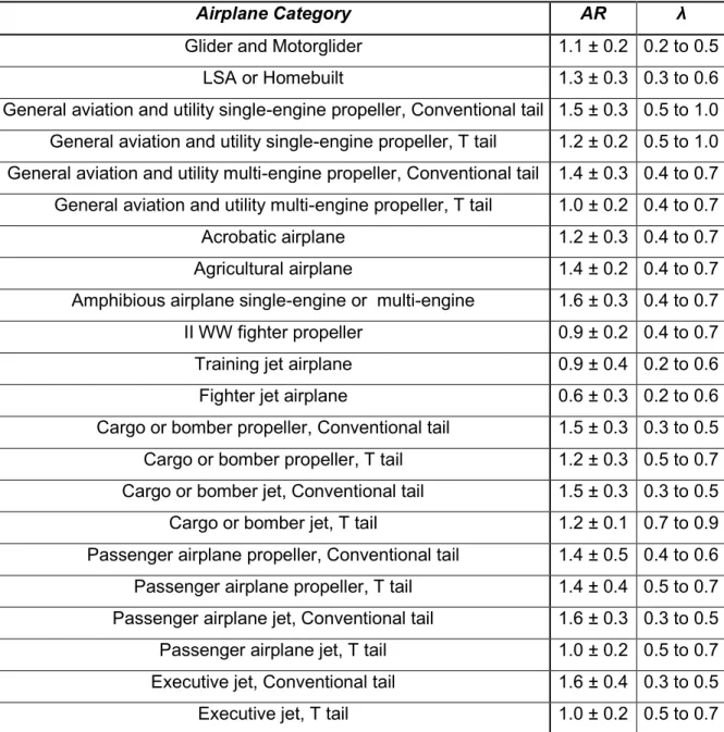
Table 2.1 - Historical tendencies data for wing aspect ratio and taper ratio (After Venson, 2013).
... 18
Table 2.2 - Historical tendencies data for wing dihedral (After Venson, 2013). ... 19
Table 2.3 - Historical tendencies data for horizontal tail aspect ratio and taper ratio (After Venson, 2013). ... 19
Table 2.4 - Historical tendencies data for vertical tail aspect ratio and taper ratio (After Venson, 2013). ... 20
Table 2.5 - Historical tendencies data for airplane wetted area (After Venson, 2015). ... 21
Table 2.6 - Reference friction coefficient values (After Venson, 2015). ... 22
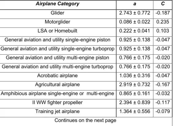
Table 2.7 - Historical tendencies values for the empty-to-take-off weight ratio constants (After Venson, 2015). ... 24
Table 2.8 - Historical tendencies data for flight phase weight fraction (After Venson, 2015). ... 26
Table 2.9 - Historical tendencies data for wing loading (After Venson, 2015). ... 27
Table 2.10 - Constants for empirical estimative for the wing loading (After Venson, 2015) .... 28
Table 2.11 - Constants for empirical estimative for the power-to-weight ratio (After Venson, 2015). ... 30
Table 2.12 - Historical tendencies data for power-to-weight ratio (After Venson, 2015). ... 30
Table 2.13 - Constants for empirical estimative for the thrust-to-power ratio (After Venson, 2015). ... 31
Table 2.14 - Historical tendencies data for thrust-to-disc loading ratio (After Venson, 2015). .... 32
Table 2.15 - Historical tendencies data for thrust-to-weight ratio (After Venson, 2015). ... 32
Table 2.16 - Historical tendencies data for take-off runway (After Venson, 2015). ... 33
Table 2.17 - Historical tendencies data for landing runway (After Venson, 2015). ... 34
Table 2.18 - Historical tendencies data for fuselage sizing (After Venson, 2015). ... 36
Table 2.19 - Historical tendencies for cockpit sizing (After Venson, 2014). ... 37
Table 2.20 - Historical tendencies data for tail volume coefficient (After Venson, 2015). ... 38
Table 2.21 - Historical tendencies data for primary control surfaces (After Venson, 2015). ... 39
Table 2.22 - Historical tendencies data for moment of inertia (After Venson, 2015). ... 40
Table 2.23 - Stability requirements values (Sadraey, 2013). ... 85
Table 2.25 - Take-off rotational acceleration for various aircraft (Sadraey, 2013). ... 97
Table 2.26 - Rudder design requirements (Sadraey, 2013). ... 108
Table 2.27 - Variation of response with damping ratio (Nelson, 1998). ... 116
Table 2.28 - Aircraft classes (Sadraey, 2013). ... 119
Table 2.29 - Flight phase categories (Sadraey, 2013). ... 120
Table 2.30 - Levels of acceptability (Sadraey, 2013). ... 120
Table 2.31 - Short-period mode damping ratio specification (Sadraey, 2013). ... 120
Table 2.32 - Phugoid mode requirement (Sadraey, 2013). ... 121
Table 2.33 - Roll control requirements (Sadraey, 2013). ... 126
Table 2.34 - Roll mode specification maximum value (Sadraey, 2013). ... 126
Table 2.35 - Time to double amplitude in spiral mode (Sadraey, 2013). ... 127
Table 2.36 - Dutch-roll mode handling qualities (Sadraey, 2013). ... 127
Table 2.37 - Take-off parameters. ... 129
Table 2.38 - Wheel-ground rolling friction coefficient. ... 129
Table 2.39 - Aircrafts flight ceilings. ... 131
Table 3.1 - Total range estimated for the airplane UFU-1. ... 149
Table 3.2 - CG positioning for some weights configurations. ... 153
Table 3.3 - Airfoils stall characteristics. ... 166
Table 3.4 - Airfoils drag polar bottom and pitch moment. ... 167
Table 3.5 - Lift increment due the global wash fields, comparison.... 194
Table 3.6 - Mass configurations for dynamics of flight assessing. ... 198
Table 3.7 - Mass configurations for dynamics of flight assessing continuation. ... 199
Table 3.8 - Trimmed cruise flight configuration for dynamics of flight assessing. ... 200
Table 3.9 - Trimmed cruise flight configuration for dynamics of flight assessing continuation. . 200 Table 3.10 - Longitudinal static stability results. ... 202
Table 3.11 - Longitudinal static stability results continuation. ... 202
Table 3.12 - Longitudinal static stability results continuation. ... 202
Table 3.13 - Longitudinal control dimensioning parameters and results. ... 205
Table 3.14 - Longitudinal control dimensioning parameters and results continuation. ... 205
Table 3.15 - Lateral control dimensioning parameters and results. ... 208
Table 3.16 - Lateral control dimensioning parameters and results continuation. ... 208
Table 3.17 - Directional static stability results.... 210
Table 3.19 - Directional control dimensioning parameters and results. ... 212
Table 3.20 - Longitudinal dynamic stability results. ... 213
Table 3.21 - Longitudinal dynamic stability results continuation. ... 214
Table 3.22 - Lateral-directional dynamic stability results. ... 216
Table 3.23 - Lateral-directional dynamic stability results continuation. ... 216
Table 3.24 - Take-off estimative airplane setting. ... 225
Table 3.25 - Take-off estimative setting and runway parameters. ... 225
Table 3.26 - Take-off estimative results. ... 226
Table 3.27 - Climb estimative airplane setting. ... 226
Table 3.28 - Climb estimative airplane setting continuation. ... 226
Table 3.29 - Climb estimative results. ... 227
Table 3.30 - Descent estimative airplane setting. ... 228
Table 3.31 - Descent estimative results. ... 228
Table 3.32 - Landing estimative airplane setting. ... 228
Table 3.33 - Landing estimative airplane setting continuation. ... 229
Table 3.34 - Landing estimative results. ... 229
LIST OF SYMBOLS
Roman Symbols
𝑎0 Airfoil lift curve slope
𝑏 Aerodynamic surface span
𝑏𝐴 Aileron span
𝑏𝐴𝑖 Location of the inner chord of the aileron along the y axis
𝑏𝐶𝐴𝑁 Canard span
𝑏𝐶𝐴𝑁_𝐵 Biplane canard span
𝑏𝐶𝐴𝑁_𝐿𝑂𝑊 Lower canard span
𝑏𝐶𝐴𝑁_𝑈𝑃 Upper canard span
𝑏𝐸 Elevator span
𝑏𝐸𝑖 Elevator inner position along the canard span
𝑏𝐹 Flap span
𝑏𝐹𝑖 Location of the inner chord of the flap along the y axis 𝑏𝑙𝑜𝑛𝑔 Longest wing or canard span
𝑏𝑅 Rudder span
𝑏𝑅𝑖 Rudder inner position along the vertical tail span 𝑏𝑉𝑇 Vertical tail span
𝑏𝑉𝑇_𝐿𝐸𝐹 Left vertical tail span
𝑏𝑉𝑇_𝑅𝐼𝐺 Right vertical tail span
𝑏𝑊 Wing span
𝑏𝑊_𝐵 Biplane wing span
𝑏𝑊_𝑈𝑃 Upper wing span
𝑐𝑑 Airfoil drag coefficient
𝑐𝑑
𝑐Experimental steady state cross-flow drag coefficient of a circular cylinder
𝑐𝑑𝐶𝐴𝑁 Canard airfoil drag coefficient
𝑐𝑑𝑝 Airfoil pressure drag coefficient
𝑐𝑑𝑉𝑇 Vertical tail airfoil drag coefficient
𝑐𝑑𝑤 Airfoil wave drag coefficient
𝑐𝑑𝑊 Wing airfoil drag coefficient
𝑐𝑑0 Airfoil zero lift drag coefficient
𝑐𝑙 Airfoil lift coefficient
𝑐𝑙𝑣𝑡𝑚𝑎𝑥 Vertical tail airfoil maximum lift coefficient 𝑐𝑙𝛼 Airfoil lift curve slope
𝑐𝑙𝛼𝑐𝑎𝑛 Canards airfoil lift curve slope 𝑐𝑙𝛼𝑣𝑡 Vertical tails airfoil lift curve slope 𝑐𝑙𝛼𝑤 Wings airfoil lift curve slope
(𝑐𝑙𝛿)𝑡ℎ𝑒𝑜𝑟𝑦 Parameter based on flap size and on profile thickness ratio
𝑐𝑚 Airfoil pitch moment coefficient
𝑐𝑚𝐶𝐴𝑁_𝐿𝑂𝑊 Lower canard airfoil pitch moment coefficient
𝑐𝑚𝐶𝐴𝑁_𝑈𝑃 Upper canard airfoil pitch moment coefficient
𝑐𝑚𝑊 Wing airfoil pitch moment coefficient
𝑑 Main landing gear tire diameter
𝑑𝑐 Distance between the aircraft CG and the aerodynamic center of the airplane Projected side area
gear leg to the ground
𝑑𝑓 Fuselage equivalent diameter for maximum cross section area
𝑒 Aerodynamic surface span efficiency factor
𝑒𝐶𝐴𝑁 Canard span efficiency factor
𝑒𝐶𝐴𝑁_𝐵 Biplane canard span efficiency factor
𝑒𝑉𝑇 Vertical tail span efficiency factor
𝑒𝑉𝑇_𝐿𝐸𝐹 Left vertical tail span efficiency factor
𝑒𝑉𝑇_𝑅𝐼𝐺 Right vertical tail span efficiency factor
𝑒𝑊 Wing span efficiency factor
𝑒𝑊_𝐵 Biplane wing span efficiency factor
𝑒𝑤𝑖𝑛𝑔 Wing Oswald efficiency factor obtained from graphic
𝑒𝑜 Aerodynamic surface Oswald efficiency factor
𝑔 Gravity acceleration
ℎ Maximum fuselage depth
ℎ𝐴𝐶𝑊 Wing aerodynamic center location relative to the leading edge of its own 𝐶̅𝑊 ℎ𝑇𝑂 Take-off obstacle height
𝑖𝐶𝐴𝑁_𝐿𝑂𝑊 Lower canard incidence angle
𝑖𝐶𝐴𝑁_𝑈𝑃 Upper canard incidence angle
𝑖𝑓 Incidence of the fuselage camber line relative to the fuselage reference line at the center of each fuselage increment. The incidence angle is defined as negative for nose droop and aft upsweep.
𝑖𝐻𝑇 Horizontal tail incidence angle
𝑖𝑉𝑇_𝐿𝐸𝐹 Left vertical tail incidence angle
𝑖𝑉𝑇_𝑅𝐼𝐺 Right vertical tail incidence angle
𝑖𝑊_𝐿𝑂𝑊 Lower wing incidence angle
𝑖𝑊_𝑈𝑃 Upper wing incidence angle
𝑘𝑙𝑜𝑛𝑔 Longitudinal oscillation stiffness constant
𝑘𝑤𝑓 Wing-fuselage interference factor
𝑘1 Factor which accounts for flap chord to airfoil chord ratio different from 25%
𝑘2 Factor which accounts for the “actual flap” angle different from the “reference flap” angle
𝑘3 Factor which accounts for flap motion as a function of the flap deflection
𝑘′ Correction factor that accounts nonlinearities at high flap deflections
𝑙 Component or part moment arm
𝑙𝐶𝐴𝑁 Canard tail moment arm
𝑙
𝑓Fuselage length
𝑙𝐻𝑇 Horizontal tail moment arm
𝑙𝑉𝑇 Vertical tail moment arm
𝑚 Mass of the airplane
𝑛𝑃 Number of blades of the propeller
𝑝 Airplane roll rate due the ailerons deflection
𝑝𝑠𝑠 Airplane constant rolling rate
𝑝̇ Temporal differential rate (𝜕 𝜕𝑡⁄ ) of 𝑝
𝑞 Dynamic pressure of the air
𝑞𝑉𝑇 Dynamic pressure at the vertical tail
𝑟 Airplane yaw rate due the rudder deflection
𝑟 Ratio between the aerodynamic area of the shorter aerodynamic surface and the longer aerodynamic surface
𝑟𝑊 Ratio between the aerodynamic area of the shorter wing and the longer wing
𝑡𝑑𝑜𝑢𝑏−ℎ𝑎𝑙𝑣𝑒 Time for halving the amplitude of an oscillatory motion
𝑡𝑇𝑂 Time to the airplane take-off from the start to the obstacle position
𝑡 𝑐⁄ Airfoil thickness
𝑡 𝑐⁄ 𝐻𝑇 Horizontal tail thickness
𝑡 𝑐⁄ 𝑉𝑇 Vertical tail thickness
𝑡 𝑐⁄ 𝑊 Wing thickness
𝑤 Main landing gear tire width
𝑤𝑓 Fuselage maximum width
𝑥𝑖 Distance between the center of the projected side area of the i-th segment of the airplane and the reference line
𝑦𝐴 Location of the aileron aerodynamic center along the y axis
𝑦𝐷 Mean distance of the point of application of the rolling drag (drag generated) by the ailerons, wings, tails, fuselage; applied normally at 40% of the semi-span of the wing from the root chord)
𝐴𝐶 Aerodynamic center location of an aerodynamic body
𝐴𝐶𝐶𝐴𝑁_𝐿𝑂𝑊 Aerodynamic center location of the lower canard
𝐴𝐶𝐶𝐴𝑁_𝑈𝑃 Aerodynamic center location of the upper canard
𝐴𝐶𝑉𝑇_𝐿𝐸𝐹 Aerodynamic center location of the left vertical tail
𝐴𝐶𝑉𝑇_𝑅𝐼𝐺 Aerodynamic center location of the right vertical tail
𝐴𝐶𝑊_𝐵 Aerodynamic center location of the biplane wing
𝐴𝐶𝑊_𝐿𝑂𝑊 Aerodynamic center location of the lower wing
𝐴𝐶𝑊_𝑈𝑃 Aerodynamic center location of the upper wing
𝐴𝑖 i-th segment of the projected side area of the complete airplane
𝐴𝑅𝐵 Biplane aspect ratio
𝐴𝑅𝐶𝐴𝑁 Canard aspect ratio
𝐴𝑅𝐶𝐴𝑁_𝐵 Biplane canard aspect ratio
𝐴𝑅𝐶𝐴𝑁_𝐿𝑂𝑊 Lower canard aspect ratio
𝐴𝑅𝐶𝐴𝑁_𝑈𝑃 Upper canard aspect ratio
𝐴𝑅𝐻𝑇 Horizontal tail aspect ratio
𝐴𝑅𝑉𝑇 Vertical tail aspect ratio
𝐴𝑅𝑉𝑇_𝐿𝐸𝐹 Left vertical tail aspect ratio
𝐴𝑅𝑉𝑇_𝑅𝐼𝐺 Right vertical tail aspect ratio
𝐴𝑅𝑊 Wing aspect ratio
𝐴𝑅𝑊_𝐵 Biplane wing aspect ratio
𝐴𝑅𝑊_𝐿𝑂𝑊 Lower wing aspect ratio
𝐴𝑅𝑊_𝑈𝑃 Upper wing aspect ratio
𝐵𝐸𝑊 Basic empty weight
𝐶 Damping of an oscillatory motion
𝐶𝑐𝑟 Critical damping of an oscillatory motion
𝐶𝑓𝑒 Surface friction coefficient
𝐶𝑓𝑓𝑢𝑠 Turbulent flat plate skin-friction coefficient of the fuselage
𝐶𝑓𝑊 Turbulent flat plate friction coefficient of the wing 𝐶𝑓𝑊𝑙𝑎𝑚 Wing laminar friction coefficient
𝐶𝑓𝑊𝑡𝑢𝑟𝑏 Wing turbulent friction coefficient
𝐶𝑙𝐶𝐺 Airplane rolling moment coefficient at the CG
𝐶𝑚 Airplane pitch moment coefficient
𝐶𝑚𝐶𝐺 Airplane pitch moment coefficient applied on the CG of the own airplane
𝐶𝑚𝐶𝐺𝐶𝐴𝑁_𝐿𝑂𝑊 Lower canard pitch moment coefficient applied on the CG of the airplane 𝐶𝑚𝐶𝐺𝐶𝐴𝑁_𝑈𝑃 Upper canard pitch moment coefficient applied on the CG of the airplane 𝐶𝑚𝐶𝐺𝐹𝑈𝑆 Fuselage pitch moment coefficient applied on the CG of the airplane 𝐶𝑚𝐶𝐺𝐻𝑇 Horizontal tail pitch moment coefficient applied on the CG of the airplane 𝐶𝑚𝐶𝐺𝑊 Wing pitch moment coefficient applied on the CG of the airplane
𝐶𝑚𝐶𝐺𝑊_𝐿𝑂𝑊 Lower wing pitch moment coefficient applied on the CG of the airplane 𝐶𝑚𝐶𝐺𝑊_𝑈𝑃 Upper wing pitch moment coefficient applied on the CG of the airplane 𝐶𝑚𝛼𝐶𝐺 Airplane pitch moment coefficient curve slope at CG
𝐶𝑚𝛼𝐶𝐴𝑁_𝐿𝑂𝑊 Lower canard pitch moment coefficient curve slope 𝐶𝑚𝛼𝐶𝐴𝑁_𝑈𝑃 Upper canard pitch moment coefficient curve slope 𝐶𝑚𝛼𝐹𝑈𝑆 Fuselage pitch moment coefficient curve slope 𝐶𝑚𝛼𝐻𝑇 Horizontal tail pitch moment coefficient curve slope 𝐶𝑚𝛼𝑊 Wing pitch moment coefficient curve slope
𝐶𝑚𝛿𝐸 Coefficient of pitch moment rate due the elevator deflection 𝐶𝑚0𝐶𝐺 Airplane zero lift pitch moment coefficient at CG
𝐶𝑚0𝐶𝐴𝑁_𝐿𝑂𝑊 Lower canard zero lift pitch moment coefficient 𝐶𝑚0𝐶𝐴𝑁_𝑈𝑃 Upper canard zero lift pitch moment coefficient 𝐶𝑚0𝐹𝑈𝑆 Fuselage zero lift pitch moment coefficient 𝐶𝑚0𝐻𝑇 Horizontal tail zero lift pitch moment coefficient 𝐶𝑚0𝑊 Wing zero lift pitch moment coefficient
𝐶𝑛𝛽𝐶𝐺 Airplane yaw moment coefficient curve slope at the CG
𝐶𝑛𝛽𝑑𝑦𝑛 Airplane dynamic yaw moment coefficient curve slope at the CG 𝐶𝑛𝛽𝑉𝑇 Vertical tail yaw moment coefficient curve slope
𝐶𝑛𝛽𝑉𝑇_𝐿𝐸𝐹 Left verticl tail yaw moment coefficient curve slope 𝐶𝑛𝛽𝑉𝑇_𝑅𝐼𝐺 Right verticl tail yaw moment coefficient curve slope 𝐶𝑛𝛽𝑊_𝐵−𝐹𝑈𝑆 Biplane wing-fuselage yaw moment coefficient curve slope 𝐶𝑛𝛿𝑅 Coefficient of yaw moment rate due the rudder deflection 𝐶𝑟𝑜𝑜𝑡 Aerodynamic surface root chord
𝐶𝑟𝑜𝑜𝑡𝐴 Aileron root chord 𝐶𝑟𝑜𝑜𝑡𝐶𝐴𝑁_𝐿𝑂𝑊 Lower canard root chord 𝐶𝑟𝑜𝑜𝑡𝐶𝐴𝑁_𝑈𝑃 Upper canard root chord 𝐶𝑟𝑜𝑜𝑡𝐸 Elevator root chord 𝐶𝑟𝑜𝑜𝑡𝐹 Flap root chord 𝐶𝑟𝑜𝑜𝑡𝑅 Rudder root chord
𝐶𝑟𝑜𝑜𝑡𝑉𝑇_𝐿𝐸𝐹 Left vertical tail root chord 𝐶𝑟𝑜𝑜𝑡𝑉𝑇_𝑅𝐼𝐺 Right vertical tail root chord 𝐶𝑟𝑜𝑜𝑡𝑊_𝐵 Biplane wing root chord 𝐶𝑟𝑜𝑜𝑡𝑊_𝐿𝑂𝑊 Lower wing root chord 𝐶𝑟𝑜𝑜𝑡𝑊_𝑈𝑃 Upper wing root chord
𝐶𝑡𝑖𝑝 Aerodynamic surface tip chord
𝐶𝑡𝑖𝑝𝐸 Elevator tip chord 𝐶𝑡𝑖𝑝𝐹 Flap tip chord 𝐶𝑡𝑖𝑝𝑅 Rudder tip chord
𝐶𝑡𝑖𝑝𝑉𝑇_𝐿𝐸𝐹 Left vertical tail tip chord 𝐶𝑡𝑖𝑝𝑉𝑇_𝑅𝐼𝐺 Right vertical tail tip chord 𝐶𝑡𝑖𝑝𝑊_𝐿𝑂𝑊 Lower wing tip chord 𝐶𝑡𝑖𝑝𝑊_𝑈𝑃 Upper wing tip chord
𝐶𝐴 Aileron chord
𝐶𝐶𝐴𝑁 Canard chord
𝐶𝐷 Airplane or body drag coefficient
𝐶𝐷𝐶𝐴𝑁 Canard drag coefficient
𝐶𝐷𝐶𝐴𝑁_𝑓𝑎𝑖𝑟_𝑙𝑒𝑓 Canards left fairing drag coefficient
𝐶𝐷𝐶𝐴𝑁_𝑓𝑎𝑖𝑟_𝑟𝑖𝑔 Canards right fairing drag coefficient
𝐶𝐷𝐶𝐴𝑁_𝐿𝑂𝑊 Lower canard drag coefficient
𝐶𝐷𝐶𝐴𝑁_𝑈𝑃 Upper canard drag coefficient
𝐶𝐷𝐹𝐴𝐼𝑅_𝐶𝐴𝑁 Canards fairing drag coefficient
𝐶𝐷𝐹𝑈𝑆 Fuselage drag coefficient
𝐶𝐷𝑖 Airplane or body induced drag coefficient
𝐶𝐷𝑖𝑊 Wing induced drag coefficient 𝐶𝐷𝑖𝑊_𝐿𝑂𝑊 Lower wing induced drag coefficient 𝐶𝐷𝑖𝑊_𝑈𝑃 Upper wing induced drag coefficient
𝐶𝐷
𝐿𝑓𝑢𝑠Fuselage induced drag coefficient
𝐶𝐷𝐿𝐺𝐸𝐴𝑅 Landing gear drag coefficient
𝐶𝐷𝑃𝑅𝑂𝑃 Propeller drag coefficient
𝐶𝐷𝑅 Airplane drag coefficient at rolling condition (between 0.7 and 1.2) 𝐶𝐷𝑉𝑇 Vertical tail drag coefficient
𝐶𝐷𝑉𝑇_𝐵𝑂𝑂𝑀 Vertical tail booms drag coefficient
𝐶𝐷𝑉𝑇_𝐿𝐸𝐹 Left vertical tail drag coefficient
𝐶𝐷𝑉𝑇_𝑅𝐼𝐺 Right vertical tail drag coefficient
𝐶𝐷𝑊 Wing drag coefficient
𝐶𝐷𝑊_𝐿𝑂𝑊 Lower wing drag coefficient
𝐶𝐷𝑊_𝑈𝑃 Upper wing drag coefficient
𝐶𝐷𝑦 Airplane side drag coefficient (typical values for conventional shape airplane
are between 0.5 and 0.8)
𝐶𝐷0
Airplane or body equivalent profile drag coefficient𝐶𝐷0𝐶𝐴𝑁 Canard airfoil drag coefficient 𝐶𝐷0𝐶𝐴𝑁_𝐿𝑂𝑊 Lower canard airfoil drag coefficient 𝐶𝐷0𝐶𝐴𝑁_𝑈𝑃 Upper canard airfoil drag coefficient 𝐶𝐷0𝑓𝑢𝑠 Fuselage equivalent profile drag coefficient 𝐶𝐷0𝑉𝑇 Vertical tail airfoil drag coefficient
𝐶𝐷0𝑊 Wing airfoil drag coefficient 𝐶𝐷0𝑊_𝐿𝑂𝑊 Lower wing airfoil drag coefficient 𝐶𝐷0𝑊_𝑈𝑃 Upper wing airfoil drag coefficient
𝐶𝐸 Elevator chord
𝐶𝐹 Flap chord
𝐶𝐻𝑇 Horizontal tail chord
𝐶𝐿 Airplane or body lift coefficient
𝐶𝐿𝐶𝐴𝑁 Canard lift coefficient
𝐶𝐿𝐶𝐴𝑁_𝐿𝑂𝑊 Lower canard lift coefficient
𝐶𝐿𝐶𝐴𝑁_𝑈𝑃 Upper canard lift coefficient
𝐶𝐿𝐶𝐴𝑁_𝐿𝑂𝑊𝛿𝐸 Lower canard lift coefficient increment due the elevator deflection
𝐶𝐿𝐶𝐴𝑁_𝑈𝑃𝛿𝐸 Upper canard lift coefficient increment due the elevator deflection
𝐶𝐿𝐹𝑈𝑆 Fuselage lift coefficient
𝐶𝐿𝐻𝑇 Horizontal tail lift coefficient
𝐶𝐿𝐻𝑇𝛿𝐸 Horizontal tail lift coefficient rate due the elevator deflection 𝐶𝐿𝑚𝑎𝑥 Airplane maximum lift coefficient
𝐶𝐿𝑚𝑎𝑥𝑇𝑂 Airplane maximum lift coefficient at the Take-off phase 𝐶𝐿𝑡𝑎𝑘𝑒−𝑜𝑓𝑓 Airplane takeoff lift coefficient
𝐶𝐿𝑉𝑇 Vertical tail lift coefficient
𝐶
𝐿𝑉𝑇_𝐿𝐸𝐹𝛿𝑅 Left vertical tail lift coefficient increment due the rudder deflection𝐶
𝐿𝑉𝑇_𝑅𝐼𝐺𝛿𝑅 Right vertical tail lift coefficient increment due the rudder deflection𝐶𝐿𝑊 Wing lift coefficient
𝐶𝐿𝑊_𝑈𝑃 Upper wing lift coefficient
𝐶𝐿𝛼𝐴𝑃 Airplane lift coefficient curve slope 𝐶𝐿𝛼𝐶𝐴𝑁 Canard lift coefficient curve slope 𝐶𝐿𝛼𝐶𝐴𝑁_𝐿𝑂𝑊 Lower canard lift coefficient curve slope 𝐶𝐿𝛼𝐶𝐴𝑁_𝑈𝑃 Upper canard lift coefficient curve slope 𝐶𝐿𝛼𝐹 Fuselage lift coefficient curve slope 𝐶𝐿𝛼𝐻𝑇 Horizontal tail lift coefficient curve slope 𝐶𝐿𝛼,𝑠𝑢𝑟𝑓𝑎𝑐𝑒 Aerodynamic surface lift coefficient curve slope
𝐶𝐿𝛼𝑉𝑇 Vertical tail lift coefficient curve slope 𝐶𝐿𝛼𝑉𝑇_𝐿𝐸𝐹 Left vertical tail lift coefficient curve slope 𝐶𝐿𝛼𝑉𝑇_𝑅𝐼𝐺 Right vertical tail lift coefficient curve slope 𝐶𝐿𝛼𝑊 Wing lift coefficient curve slope
𝐶𝐿𝛼𝑊_𝐵 Biplane wing lift coefficient curve slope 𝐶𝐿𝛼𝑊−𝐹 Wing-fuselage lift coefficient curve slope 𝐶𝐿𝛼𝑊_𝐿𝑂𝑊 Lower wing lift coefficient curve slope 𝐶𝐿𝛼𝑊_𝑈𝑃 Upper wing lift coefficient curve slope
𝐶𝐿𝛼=0𝐴𝑃 Airplane lift coefficient for angle of attack equal to zero 𝐶𝐿𝛼=0𝐶𝐴𝑁_𝐿𝑂𝑊 Lower canard lift coefficient for angle of attack equal to zero 𝐶𝐿𝛼=0𝐶𝐴𝑁_𝑈𝑃 Upper canard lift coefficient for angle of attack equal to zero 𝐶𝐿𝛼=0𝑊 Wing lift coefficient for angle of attack equal to zero
𝐶𝐿0
Airplane or body lift coefficient for angle of attack equal to zero𝐶𝑅 Rudder chord
𝐶𝑉𝑇 Vertical tail chord
𝐶̅ Mean aerodynamic chord
𝐶̅𝐶𝐴𝑁 Canard mean aerodynamic chord
𝐶̅𝐶𝐴𝑁_𝐿𝑂𝑊 Lower canard mean aerodynamic chord
𝐶̅𝐶𝐴𝑁_𝑈𝑃 Upper canard mean aerodynamic chord
𝐶̅𝐻𝑇 Horizontal tail mean aerodynamic chord
𝐶̅𝑉𝑇 Vertical tail mean aerodynamic chord
𝐶̅𝑉𝑇_𝐿𝐸𝐹 Left vertical tail mean aerodynamic chord
𝐶̅𝑉𝑇_𝑅𝐼𝐺 Right vertical tail mean aerodynamic chord
𝐶̅𝑊 Wing mean aerodynamic chord
𝐶̅𝑊_𝐵 Biplane wing mean aerodynamic chord
𝐶̅𝑊_𝐿𝑂𝑊 Lower wing aerodynamic chord
𝐶̅𝑊_𝑈𝑃 Upper wing aerodynamic chord
𝐷 Drag generated by the airplane
𝐷𝑖 Induced drag generated by the airplane
𝐷𝑖𝐴_𝑙𝑒𝑓𝑡 Induced drag due the left aileron deflection
𝐷𝑖𝐴_𝑟𝑖𝑔ℎ𝑡 Induced drag due the right aileron deflection
𝐷𝑃 Propeller diameter
𝐸 Flight endurance
𝐹𝐴𝑦 Airplane aerodynamic side force
𝐹𝐿 Flight level
𝐺𝐴𝑃𝐶𝐴𝑁_𝐵 Biplane canard gap
𝐺𝐴𝑃𝑊_𝐵 Biplane wing gap
𝐺𝐴𝑆𝑇𝑂𝐹 Fuel consumption during the take-off phase
𝐻𝐻𝑇 Horizontal tail height above fuselage
𝐻𝐻𝑇⁄𝐻𝑉𝑇 0.0 for conventional tail; 1.0 for “T” tail
𝐻𝑉𝑇 Vertical tail height above fuselage
𝐼𝑥𝑥𝑐𝑔 Airplane moment of inertia at the CG around the X axis
𝐼𝑦𝑦𝑚𝑔 Airplane moment of inertia at the main landing gear leg around the Y axis 𝐼𝑦𝑦𝑐𝑔 Airplane moment of inertia at the CG around the Y axis
𝐼𝑧𝑧𝑐𝑔 Airplane moment of inertia at the CG around the Z axis 𝐼𝑆𝐴 International standard atmosphere
𝐾𝑓2 Parameter of the fuselage contribution to the directional stability, that depends Of the fuselage shape and its projected side area (Typical between 1.3 to 1.4)
𝐾𝑆𝑇𝐴𝑇 Static margin of the airplane
𝐾2− 𝐾1 Correction factor for the body (fuselage) fineness ratio
𝐿 Lift generated by the airplane
𝐿𝑚 Extended length of main landing gear
𝐿𝑛 Extended length of nose landing gear
𝐿𝑟𝑒𝑓 Body reference length
𝐿𝐴 Rolling moment due the ailerons deflection
𝐿𝑆𝐴 Light sport airplane
𝐿𝑉𝑇 Lift generated by the vertical tail
𝐿 𝐷⁄ Airplane aerodynamic efficiency
𝑀 Flight Mach number
𝑀𝑎 Pitch moment due the inercial force
𝑀𝑎𝑐ℎ Horizontal tail pitch moment 𝑀𝑎𝑐𝑤𝑓 Wing-Fuselage pitch moment
𝑀𝑚𝑔 Pitch moment at the main landing gear leg
𝑀𝐶𝐴𝑁_𝐿𝑂𝑊 Lower canard pitch moment
𝑀𝐶𝐴𝑁_𝑈𝑃 Upper canard pitch moment
𝑀𝐹𝑈𝑆 Fuselage canard pitch moment
𝑀𝑊_𝐿𝑂𝑊 Lower wing pitch moment
𝑀𝑊_𝑈𝑃 Upper wing pitch moment
𝑀𝐷 Airplane pitch moment due the drag
𝑀𝐷𝐶𝐴𝑁_𝐿𝑂𝑊 Lower canard pitch moment due its own drag 𝑀𝐷𝐶𝐴𝑁_𝑈𝑃 Upper canard pitch moment due its own drag 𝑀𝐷𝐹𝑈𝑆 Fuselage pitch moment due its own drag 𝑀𝐷𝑊_𝐿𝑂𝑊 Lower wing pitch moment due its own drag 𝑀𝐷𝑊_𝑈𝑃 Upper wing pitch moment due its own drag 𝑀𝐷𝑉𝑇_𝐿𝐸𝐹 Left vertical tail pitch moment due its own drag 𝑀𝐷𝑉𝑇_𝑅𝐼𝐺 Right vertical tail pitch moment due its own drag 𝑀𝐿 Airplane pitch moment due the lift
𝑀𝐿𝑤𝑓 Wing-Fuselage pitch moment due its own lift 𝑀𝐿𝑊_𝐿𝑂𝑊 Lower wing pitch moment due its own lift 𝑀𝐿𝑊_𝑈𝑃 Upper wing pitch moment due its own lift 𝑀𝑇 Pitch moment due the propeller thrust
𝑀𝑇𝑂𝑊 Maximum take-off weight
𝑀𝑊 Pitch momet due the airplane weight
𝑁𝑐𝑟𝑒𝑤 Number of crew
𝑁𝑑𝑜𝑢𝑏−ℎ𝑎𝑙𝑣𝑒 Number of cycles for doubling or halving the amplitude of an oscillatory motion
𝑁𝑒𝑛𝑔 Number of engines
𝑁𝑔𝑒𝑎𝑟 Landing load factor
𝑁𝑡 Number of fuel tanks
𝑁𝑦 Limit in flight load factor
𝑁𝐴 Airplane yawing moment at the CG
𝑁𝐿.𝑈 Ultimate landing load factor
𝑁𝑈 Ultimate in flight load factor
𝑂𝐸𝑊 Operational empty weight
𝑃 Period of an oscillatory motion
𝑃𝑐𝑙𝑖𝑚𝑏 Climb engine power
𝑃𝑇𝑂 Take-off power available corrected by the propeller efficiency
𝑃𝑆𝑇𝑂 Engine shaft power at the take-off phase 𝑅 Range of cruise flight
𝑅𝑐𝑓 Canard-fuselage interference factor
𝑅𝑒 Reynolds number
𝑅𝑤𝑓 Wing-fuselage interference factor
𝑅𝐴_𝑙𝑒𝑓𝑡 Left aileron turning radius
𝑅𝐴_𝑟𝑖𝑔ℎ𝑡 Right aileron turning radius
𝑅𝐿𝑆 Lifting surface correction factor
𝑅𝑇 Take-off runway distance
𝑆 Aerodynamic surface reference area
𝑆𝑎𝑒𝑟𝑜 Surface or body aerodynamic area
𝑆𝑎𝑒𝑟𝑜𝐶𝐴𝑁 Canard aerodynamic area
𝑆𝑎𝑒𝑟𝑜𝐶𝐴𝑁_𝐵𝐼𝑃 Biplane total canard aerodynamic area 𝑆𝑎𝑒𝑟𝑜𝐶𝐴𝑁_𝐿𝑂𝑊 Lower canard aerodynamic area 𝑆𝑎𝑒𝑟𝑜𝐶𝐴𝑁_𝑈𝑃 Upper canard aerodynamic area 𝑆𝑎𝑒𝑟𝑜𝑉𝑇 Vertical tail aerodynamic area 𝑆𝑎𝑒𝑟𝑜𝑉𝑇_𝐿𝐸𝐹 Left vertical tail aerodynamic area 𝑆𝑎𝑒𝑟𝑜𝑉𝑇_𝑅𝐼𝐺 Right vertical tail aerodynamic area 𝑆𝑎𝑒𝑟𝑜𝑊 Wing aerodynamic area
𝑆𝑎𝑒𝑟𝑜𝑊_𝐵𝐼𝑃 Biplane total wing aerodynamic area 𝑆𝑎𝑒𝑟𝑜𝑊_𝐿𝑂𝑊 Lower wing aerodynamic area 𝑆𝑎𝑒𝑟𝑜𝑊_𝑈𝑃 Upper wing aerodynamic area 𝑆𝑎𝑖𝑙 Total aileron area
𝑆𝑏𝑓𝑢𝑠 End of the fuselage cross section area 𝑆𝑓𝑢𝑠 Fuselage wetted area
𝑆𝑝 Propeller disc loading area
𝑆𝑟𝑢𝑑 Total rudder area
𝑆𝑤𝑒𝑡𝑎𝑝 Airplane total wetted area 𝑆𝑤𝑒𝑡𝐶𝐴𝑁_𝑓𝑎𝑖𝑟_𝑙𝑒𝑓 Canards left fairing wetted area 𝑆𝑤𝑒𝑡𝐶𝐴𝑁_𝑓𝑎𝑖𝑟_𝑟𝑖𝑔 Canards right fairing wetted area
𝑆
𝑤𝑒𝑡−𝑓𝑢𝑠Fuselage wetted area
𝑆𝑤𝑒𝑡𝑉𝑇_𝑏𝑜𝑜𝑚 Vertical tail boom wetted area 𝑆𝑤𝑒𝑡𝐿𝐺𝐸𝐴𝑅 Landing gear wetted area
𝑆𝐴 Aileron area
𝑆𝐶𝐴𝑁 Canard reference area
𝑆𝐶𝐴𝑁_𝐵𝐼𝑃 Biplane canard reference area
𝑆𝐶𝐴𝑁_𝐿𝑂𝑊 Lower canard reference area
𝑆𝐶𝐴𝑁_𝑈𝑃 Upper canard reference area
𝑆𝐸 Total elevator area
𝑆𝐸𝑃 Shaft engine power
𝑆𝐻𝑃𝑟𝑎𝑡𝑒𝑑 Shaft horse power for the actual flight condition
𝑆𝐹𝐶 Specific fuel consumption
𝑆𝐹𝐶𝐶𝑅𝑈 Specific fuel consumption during the cruise phase
𝑆𝐹𝐶𝑇𝑂 Specific fuel consumption during the take-off phase
𝑆𝐹𝑚𝑎𝑥−𝑐𝑠 Fuselage maximum cross section area 𝑆𝐹𝑙𝑎𝑝 Total area of flaps extended
𝑆𝐹_𝑠 Fuselage projected side area
𝑆𝐻𝑇 Horizontal tail reference area
𝑆𝑅 Rudder area
𝑆𝑇 Total biplane wing or canard reference area
𝑆𝑇𝑂 Total take-off distance
𝑆𝑇𝑂𝐴 Airborne take-off distance 𝑆𝑇𝑂𝐺 Ground take-off distance 𝑆𝑉𝑇 Vertical tail reference area
𝑆𝑉𝑇_𝐿𝐸𝐹 Left vertical tail reference area
𝑆𝑉𝑇_𝑅𝐼𝐺 Right vertical tail reference area
𝑆𝑊 Wing reference area
𝑆𝑊_𝐵𝐼𝑃 Biplane wing reference area
𝑆𝑊_𝐿𝑂𝑊 Lower wing reference area
𝑆𝑊_𝑈𝑃 Upper wing reference area
𝑆𝑊𝑓 Wing flapped area 𝑆𝑊𝑤𝑒𝑡 Wing wetted area
𝑆𝑊𝑤𝑒𝑡𝑙𝑎𝑚 Wing wetted area part exposed to laminar flow
𝑇 Thrust generated by the propeller
𝑇𝐹𝑊 Total fuel weight
𝑇𝑂𝑃 Take-off parameter (used for estimate the take-off runway distance)
𝑇𝑂𝑊 Take-off weight
𝑇̅ Mean thrust ratio at the speed 0.707 ∙ 𝑉𝐿𝑂𝐹
𝑈0 Freestream velocity
𝑈1 Airplane landing speed
𝑉𝑓.𝑡 Total fuel tanks volume, gallon
𝑉𝑓𝑢 Total fuel volume, gallon
𝑉𝐴_𝑙𝑒𝑓𝑡 Aerodynamic speed at the left aileron
𝑉𝐴_𝑟𝑖𝑔ℎ𝑡 Aerodynamic speed at the right aileron
𝑉𝐶𝐴𝑁 Canard volume coefficient
𝑉𝐶𝐴𝑁_𝐿𝑂𝑊 Lower canard volume coefficient
𝑉𝐶𝐴𝑁_𝑈𝑃 Upper canard volume coefficient
𝑉𝐻𝑇 Horizontal tail volume coefficient
𝑉𝑀𝐶 Airplane minimum control speed
𝑉𝑅 Airplane rotation speed during the take-off running
𝑉𝑆 Stall speed
𝑉𝑆𝑇𝑂 Stall speed in the take-off configuration 𝑉𝑆𝑂 Stall speed at landing configuration
𝑉𝑇 Airplane total speed or relative wind
𝑉𝑇𝐷 Airplane touch down speed
𝑉𝑇𝑂 Take-off speed
𝑉𝑉𝑇 Vertical tail volume coefficient
𝑉𝑊 Cross wind speed
𝑉0 Cruise or Loiter phase flight speed
𝑉3 Speed at the obstacle
𝑊 Airplane actual weight
𝑊𝐶𝑜𝑛𝑡𝑟𝑜𝑙.𝑆𝑢𝑟𝑓 Primary flight control surfaces weight
𝑊𝑒 Airplane weight at the end of the cruise flight
𝑊𝑒𝑚𝑝𝑡𝑦 Airplane operational empty weight
𝑊𝑒𝑛𝑔 Engine gross weight
𝑊𝑓𝑢𝑒𝑙.𝑠𝑦𝑠𝑡 Fuel system weight
𝑊𝑓𝑢𝑠 Fuselage weight
𝑊𝑖 Airplane weight at the beginning of the cruise flight
𝑊𝑙 Airplane landing gross weight
𝑊𝑜𝑖𝑙.𝑠𝑦𝑠𝑡 Oil system weight
𝑊𝑝𝑎𝑦𝑙𝑜𝑎𝑑 Payload weight
𝑊𝑝𝑖𝑙𝑜𝑡 Pilot weight
𝑊𝑝𝑟𝑜𝑝 Propeller weight
𝑊𝑡𝑖𝑟𝑒 Weight carried by each main landing gear tire
𝑊𝐸𝑙𝑒𝑐𝑡_𝑚𝑜𝑑 Avionics electronic modulus weight
𝑊𝐹𝑙𝑎𝑝.𝑐𝑜𝑛𝑡.𝑠𝑦𝑠𝑡 Flap control system weight
𝑊𝐹𝑙𝑖𝑔.𝑐𝑜𝑛𝑡.𝑠𝑦𝑠𝑡 Flight control system weight
𝑊𝐻𝑇 Horizontal tail weight
𝑊𝑀𝐿𝐺 Main landing gear weight
𝑊𝑁𝐿𝐺 Nose landing gear weight
𝑊𝑆𝑒𝑎𝑡_𝑝𝑖𝑙 Pilot seat weight
𝑊𝑉𝑇 Vertical tail weight
𝑊𝑊 Wing weight
𝑊0 Airplane Take-off gross weight
𝑋𝑓𝑢𝑠 Length of the fuselage
𝑋𝐴𝐶𝑊_𝐵 Location of the aerodynamic center of the biplane wing related its own leading
edge
𝑋𝐶 Length of the cockpit
𝑋𝐿𝐸𝑚𝑎𝑐𝑊 Location along the 𝑥 axis of the leading edge of the mean aerodynamic chord of the wing
𝑋𝐿𝐸𝐶̅𝑊_𝐵 Location along the 𝑥 axis of the leading edge of the mean aerodynamic chord of
the biplane wing
𝑋𝑁 Length of the fuselage nose
𝑋𝑁𝑃 Airplane neutral point location along the 𝑥 axis
𝑋𝑇 Length of the fuselage tail
𝑋𝑇ℎ𝑟𝑢𝑠𝑡 Negative for the propeller disc plane behind the CG
𝑌𝐶 Width of the cockpit (maximum fuselage width)
𝑍𝑇ℎ𝑟𝑢𝑠𝑡 Negative for the propeller axis line above the CG
𝑍𝑊 Distance parallel to the z axis, from wing 25% of the chord point to the fuselage centerline
Greek Symbols
𝛼 Angle of attack
𝛼𝑐𝑙=0𝑐𝑎𝑛 Canards airfoil angle of attack for zero lift 𝛼𝑐𝑙=0𝑣𝑡 Vertical tail airfoil angle of attack for zero lift 𝛼𝑐𝑙=0𝑤 Wings airfoil angle of attack for zero lift 𝛼𝐶𝐴𝑁_𝐿𝑂𝑊 Lower canard effective angle of attack
𝛼𝐶𝐴𝑁_𝑈𝑃 Upper canard effective angle of attack
𝛼𝐻𝑇 Horizontal tail effective angle of attack
𝛼𝑊 Wing effective angle of attack
𝛼0𝑊 Wing zero-lift angle relative to the fuselage reference line
𝛽 Sideslip angle
𝛿𝐴 Aileron deflection
𝛿𝐴.𝑚𝑎𝑥 Aileron maximum deflection
𝛿𝐸 Elevator deflection
𝛿𝐸.𝑚𝑎𝑥 Elevator maximum deflection
𝛿𝑓 Flap deflection
𝛿𝑓𝑙𝑎𝑝.𝑚𝑎𝑥 Maximum flaps deflection
𝛿𝑅 Rudder deflection
𝛿𝑅.𝑚𝑎𝑥 Rudder maximum deflection
𝛿𝑇 Thrust rate
𝜀 Downwash or upwash angle
𝜀𝑢 Upwash angle
𝜀𝐶𝐴𝑁_𝐿𝑂𝑊 Lower canard downwash or upwash angle
𝜀𝐶𝐴𝑁_𝑈𝑃 Upper canard downwash or upwash angle
𝜀𝑊_𝐿𝑂𝑊 Lower wing downwash or upwash angle
𝜀0 Downwash or upwash angle for angle of attack equal to zero
𝜀0𝐶𝐴𝑁_𝐿𝑂𝑊 Lower canard downwash or upwash angle for angle of attack equal to zero
𝜀0𝐶𝐴𝑁_𝑈𝑃 Upper canard downwash or upwash angle for angle of attack equal to zero
𝜀0𝑊_𝐿𝑂𝑊 Lower wing downwash or upwash angle for angle of attack equal to zero
𝜂 Governing factor of the damping of an oscillatory motion
𝜂𝐶𝐴𝑁 Canard efficiency factor (dynamic pressure rate on the canard)
𝜂𝐶𝐴𝑁_𝐿𝑂𝑊 Lower canard efficiency factor
𝜂𝐶𝐴𝑁_𝑈𝑃 Upper canard efficiency factor
𝜂𝑃 Propeller aerodynamic efficiency
𝜂𝐻𝑇 Horizontal tail efficiency factor (dynamic pressure rate between the horizontal tail and the wing); normally between 0.8 and 1.2
𝜂𝑉𝑇 Vertical tail efficiency factor (dynamic pressure rate on the vertical tail)
𝜃0 Airplane initial pitch angle
𝜃̈ Pitch moment angular acceleration
𝜆 Aerodynamic surface planform taper ratio
𝜆𝐶𝐴𝑁 Canard taper ratio
𝜆𝐶𝐴𝑁_𝐵 Biplane canard taper ratio
𝜆𝐶𝐴𝑁_𝐿𝑂𝑊 Lower canard taper ratio
𝜆𝐶𝐴𝑁_𝑈𝑃 Upper canard taper ratio
𝜆𝐻𝑇 Horizontal tail taper ratio
𝜆𝑉𝑇 Vertical tail taper ratio
𝜆𝑉𝑇_𝐿𝐸𝐹 Left vertical tail taper ratio
𝜆𝑉𝑇_𝑅𝐼𝐺 Right vertical tail taper ratio
𝜆𝑊 Wing taper ratio
𝜆𝑊_𝐵 Biplane wing taper ratio
𝜆𝑊_𝐿𝑂𝑊 Lower wing taper ratio
𝜆𝑊_𝑈𝑃 Upper wing taper ratio
𝜇 Dynamic viscosity of the fluid
𝜇𝑔 Wheel-ground rolling friction coefficient
𝜇𝐶𝐴𝑁 Ratio between the shorter span and the longer span of the biplane canard
𝜇𝑊 Ratio between the shorter span and the longer span of the biplane wing
𝜇′ Corrected wheel-ground rolling friction coefficient
𝜉 Damping ratio of an oscillatory motion
𝜋 Trigonometric ratio of the circumference
𝜌𝑐𝑟𝑢𝑖𝑠𝑒 Air density at cruise altitude
𝜌𝐹𝐿 Air density at actual flight level
𝜌0 Air density at sea level
𝜎 Air density ratio
𝜎 Biplane Prandtl interference factor
𝜎 Airplane crab angle
𝜎 Sidewash angle
𝜎𝐶𝐴𝑁 Canard biplane Prandtl interference factor
𝜎𝑊 Wing biplane Prandtl interference factor
𝜏𝐴 Aileron effectiveness
𝜏𝐸 Elevator effectiveness
𝜏𝑅 Rudder effectiveness
∅𝑝𝑟𝑜𝑝 Propeller diameter
∅𝑓𝑢𝑠 Fuselage equivalent diameter
𝜔 Angular speed
𝜔 Damped natural frequency of an oscillatory motion
𝜔𝑛 Undamped natural frequency of an oscillatory motion
(∆𝑐𝑙𝑚𝑎𝑥)𝑏𝑎𝑠𝑒 Parameter based on a 25% “reference flap” chord to airfoil chord ratio
∆𝐴𝐶𝐶𝐴𝑁_𝐿𝑂𝑊 Shift on the aerodynamic center of the lower canard
∆𝐴𝐶𝐶𝐴𝑁_𝑈𝑃 Shift on the aerodynamic center of the upper canard
∆𝐴𝐶𝑊_𝐿𝑂𝑊 Shift on the aerodynamic center of the lower wing
∆𝐴𝐶𝑊_𝑈𝑃 Shift on the aerodynamic center of the upper wing
∆𝐶𝑙𝛽 Airplane increment of the rolling moment rate coefficient
∆𝐶𝐿𝛼𝐶𝐴𝑁_𝐿𝑂𝑊 Lower canard increment or decrement on the lift curve sole due the global wash
field
∆𝐶𝐿𝛼𝐶𝐴𝑁_𝑈𝑃 Upper canard increment or decrement on the lift curve sole due the global wash
field
∆𝐶𝐿𝛼𝑊_𝐿𝑂𝑊 Lower wing increment on the lift curve sole due the global wash field ∆𝐶𝐿𝛼𝑊_𝑈𝑃 Upper wing increment on the lift curve sole due the global wash field ∆𝐿𝐴 Wing lift increment or decrement due the ailerons deflection
𝛦 Global wash filed angle
𝛦𝐶𝐴𝑁_𝐿𝑂𝑊 Lower canard global wash field angle
𝛦𝐶𝐴𝑁_𝑈𝑃 Upper canard global wash field angle
𝛦0 Global wash field angle for angle of attack equal to zero
𝜑 Bank angle
𝛤 Aerodynamic surface dihedral angle
𝛤𝐶𝐴𝑁 Canard dihedral angle
𝛤𝐶𝐴𝑁_𝐵 Biplane canard dihedral anlge
𝛤𝐶𝐴𝑁_𝐿𝑂𝑊 Lower canard dihedral angle
𝛤𝐶𝐴𝑁_𝑈𝑃 Upper canard dihedral angle
𝛤𝑉𝑇_𝑅𝐼𝐺 Right vertical tail dihedral angle
𝛤𝑊 Wing dihedral angle
𝛤𝑊_𝐵 Biplane wing dihedral angle
𝛤𝑊_𝐿𝑂𝑊 Lower wing dihedral angle
𝛤𝑊_𝑈𝑃 Upper wing dihedral angle
𝛬 Aerodynamic surface sweep angle
𝛬𝑡𝑚𝑎𝑥 Sweep angle of the line connecting the point of maximum thickness on each
airfoil of the wing.
𝛬𝐶𝐴𝑁 Canard sweep angle at 25% of 𝐶̅𝐶𝐴𝑁
𝛬𝐶𝐴𝑁_𝐿𝑂𝑊 Lower Canard sweep angle at 25% of 𝐶̅𝐶𝐴𝑁_𝐿𝑂𝑊
𝛬𝐶𝐴𝑁_𝑈𝑃 Upper Canard sweep angle at 25% of 𝐶̅𝐶𝐴𝑁_𝑈𝑃
𝛬𝐻𝑇 Horizontal tail sweep angle at 25% of 𝐶̅𝐻𝑇
𝛬𝐿.𝐸 Aerodynamic surface leading edge sweep angle
𝛬𝑉𝑇 Vertical tail sweep angle at 25% of 𝐶̅𝑉𝑇
𝛬𝑉𝑇_𝐿𝐸𝐹 Left vertical tail sweep angle at 25% of 𝐶̅𝑉𝑇_𝐿𝐸𝐹
𝛬𝑉𝑇_𝑅𝐼𝐺 Right vertical tail sweep angle at 25% of 𝐶̅𝑉𝑇_𝑅𝐼𝐺
𝛬𝑊 Wing sweep angle at 25% of 𝐶̅𝑊
𝛬𝑊_𝐵 Biplane wing sweep angle at 25% of 𝐶̅𝑊_𝐵
𝛬𝑊_𝐿𝑂𝑊 Lower wing sweep angle at 25% of 𝐶̅𝑊_𝐿𝑂𝑊
SUMMARY
CHAPTER 1 - INTRODUCTION... 6
1.1. ABOUT THE NEW AIRPLANE... 6 1.2. BRIEF HISTORICAL PERSPECTIVE ... 9 1.3. BIBLIOGRAPHIC REVIEW ... 14
CHAPTER 2 - AIRPLANE DESIGN THEORY ... 15
2.5.9. Lateral-Directional dynamic stability ... 121 2.5.9.1. Lateral-Directional characteristic equation ... 123 2.5.9.2. Lateral-Directional state equation ... 124 2.5.9.3. Lateral-Directional stability and control derivatives ... 125 2.5.9.4. Lateral-Directional flying qualities considerations ... 126 2.6. PERFORMANCE ... 127 2.6.1. Excess of power and thrust ... 128 2.6.2. Take-off performance ... 128 2.6.3. Climb performance ... 130 2.6.3.1. Rate of climb ... 130 2.6.3.2. Climb gradient ... 130 2.6.3.3. Flight ceiling ... 131 2.6.4. Cruise performance ... 131 2.6.5. Descent performance ... 131 2.6.6. Landing performance ... 132 2.7. LOADS ... 132 2.7.1. Maneuver V-n diagram ... 133 2.7.1.1. Design airspeeds ... 133 2.7.1.2. Limit maneuvering load factors ... 134 2.8. STRUCTURAL LAYOUT ... 135 2.8.1. Wing structural layout ... 135 2.8.2. Horizontal & Vertical tail structural layout ... 137 2.8.3. Fuselage structural layout ... 137 2.9. LANDING GEAR SYSTEM ... 138 2.9.1. Main landing gear leg considerations ... 139 2.9.2. Nose landing gear leg considerations ... 139 2.9.2.1. Castoring wheel geometry ... 139 2.9.3. Tire sizing ... 140
CHAPTER 3 - DESIGN, DIMENSIONING & SPECIFICATION ... 142
3.11. PROPULSIVE SYSTEM ... 242 3.11.1. Engine ... 242 3.11.2. Propeller ... 242 3.12. AVIONIC SYSTEM ... 243 3.12.1. Main suite ... 244 3.12.2. Redundancy suite ... 246 3.12.3. Communication suite ... 246 3.12.4. Avionic panel layout ... 247 3.13. ELECTRICAL SYSTEM ... 248
CHAPTER 4 - TECHNICAL DESCRIPTION ... 250
4.1. External dimensions ... 250 4.1.1. Wings ... 250 4.1.1.1. Biplane wing ... 250 4.1.1.2. Lower wing ... 251 4.1.1.3. Upper wing ... 251 4.1.2. Canards ... 252 4.1.2.1. Biplane canard ... 252 4.1.2.2. Lower canard ... 252 4.1.2.3. Upper canard ... 253 4.1.3. Vertical tails ... 253 4.1.3.1. Left vertical tail ... 253 4.1.3.2. Right vertical tail ... 254 4.1.4. Fuselage ... 254 4.2. Airplane views ... 255 4.3. Airplane internal compartments ... 256
CHAPTER 1 -
INTRODUCTION
CHAPTER I
1.1. ABOUT THE NEW AIRPLANE
The development of a complete new airplane always was the intention for the conclusion of the undergraduation in aeronautical engineering, evolving for what is presented in this work.
The intention was to develop an airplane that it would have a very specific mission, involving theoretical and practical aspects and with an unconventional configuration.
The mission of the aircraft here developed is to serve as a technical platform for the development of studies on the aeronautical engineering, being used at the undergraduation as well as on the post-graduation levels, what would involve activities since its design, manufacturing and flying. Its main purpose is to be a flying laboratory, so as can be noted, the primary mission of this airplane do not consider basic characteristics as the flight altitude, cruise speed, range, etc, though these characteristics had been defined below.
𝑉𝑐𝑟𝑢𝑖𝑠𝑒= 170 [𝑘 𝑚 ℎ⁄ ]
𝐹𝐿𝑐𝑟𝑢𝑖𝑠𝑒 = 8000 [𝑓𝑡]
𝑅 = 600.0 [𝑘𝑚]
As complementary specification, this aircraft should be easy and safe to pilot, it should be able to receive flight test instrumentation. The airplane UFU-1 will be certified for at the experimental categories, but, complying the FAR 23 when possible.
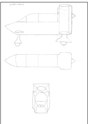
Quickly the intention of developing this airplane evolved for to be a tribute to the Alberto Santo Dumont and his 14bis presented on the Figure 1.1. At this moment the configuration of the airplane was decided, it should be a biplane equipped with canard and one pusher engine as presented on the Figure 1.2 and Figure 1.3, and its designation should be UFU-1 due the fact this airplane to be the first to be built at the Universidade Federal de Uberlândia.
technical aspects were developed as required just to support these four technologies described here. Was considered convenient to present the theory and results obtained during the conceptual design phase, intending to show how the airplane was conceived.
Figure 1.1 - 14Bis flight on October 23th, 1906. (Available in:
<
https://www.google.com.br/search?q=14bis&tbm=isch&tbo=u&source=univ&sa=X&ved=0ahUKEwic5f-T6NfWAhXFFpAKHas-B2kQsAQIQA&biw=1366&bih=651>. Access in november 11, 2017)
8
Figure 1.3 - Airplane UFU-1 initial sketch.
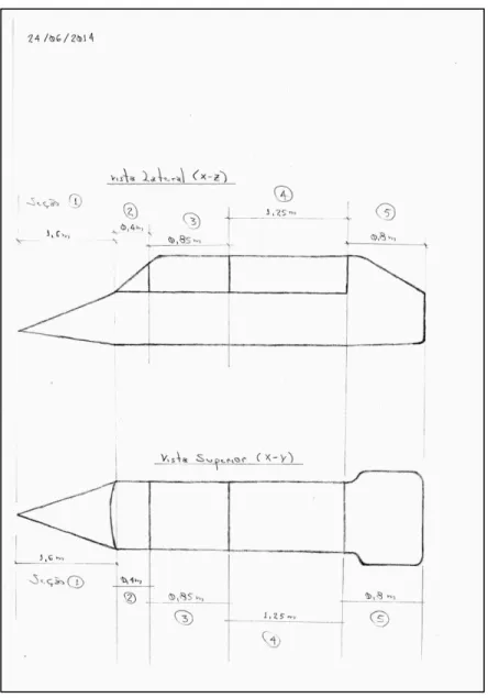
Figure 1.4 - Airplane UFU-1 final drawing.
1.2. BRIEF HISTORICAL PERSPECTIVE
The dawn of the aviation is characterized by aircrafts that employed the biplane wing configuration as the 14bis showed on the Figure 1.5, and the Wright brothers’s Flyer I showed on the Figure 1.6 that probably were the two more iconic airplanes of this historical moment.
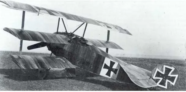
This configuration was the standard until the time of the first Great War, when practically all the airplane models conceived were biplane wing as showed on the Figure 1.8 or even triplane as the famous Fokker Dr.I piloted by the red baron and showed on the Figure 1.7.
10
Figure 1.5 - 14bis at flight. (Available in:
<
https://www.google.com.br/search?q=14bis&tbm=isch&tbo=u&source=univ&sa=X&ved=0ahUKEwic5f-T6NfWAhXFFpAKHas-B2kQsAQIQA&biw=1366&bih=651>. Access in november 11, 2017)
Figure 1.6 - Wright brothers’s Flyer I. (Available in:
<https://www.google.com.br/search?biw=1366&bih=651&tbm=isch&sa=1&q=FLYER+I+WRITE+BROTHERS&oq=FLYER+I+WRITE
Figure 1.7 - Red baron airplane, Fokker Dr.I. (Available in:
<https://www.google.com.br/search?q=bar%C3%A3o+vermelho+avi%C3%A3o&tbm=isch&tbo=u&source=univ&sa=X&ved=0ahUKE
wi9ksj169fWAhUCP5AKHTZIAIIQsAQIRA&biw=1366&bih=651#imgrc=_&spf=1507150197293>. Access in november 11,
2017)
Figure 1.8 - Airplane Spad 13, first great war. (Available in:
<https://www.google.com.br/search?q=Airplane+Spad+13&tbm=isch&tbo=u&source=univ&sa=X&ved=0ahUKEwicsYP87NfWAhXD
12
Figure 1.9 - Airliner Fokker F-10, from 1927. (Available in: <https://en.wikipedia.org/wiki/Fokker_F.10>.
Access in november 11, 2017)
Figure 1.10 - Douglas DC-3, introduction in service in 1936. (Available in:
<https://pt.wikipedia.org/wiki/Douglas_DC-3>. Access in november 11, 2017)
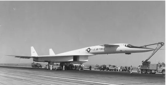
manufacturers revived this configuration as showed on the Figure 1.11. From the 70th decade such configuration started to be employed on civil airplanes of the general/executive and experimental/homebuilt categories as showed on the Figure 1.12, but, always as an exception much more than a trend. This is justified by its technical aspects related mainly to dynamics of flight, which if not treated adequately, is destabilizing.
Figure 1.11 - North American XB-70 Valkyrie, before first flight on September 21th, 1964.
(Available in: <https://en.wikipedia.org/wiki/North_American_XB-70_Valkyrie>. Access in november 11, 2017)
Figure 1.12 - Beechcraft Starship, executive airplane. (Available in: