Effect of Different Design Parameters
On Lift, Thrust and Drag of an Ornithopter
M Afzaal Malik1, Farooq Ahmad2
Abstract – Research in the field of Flapping Wing Micro Air Vehicle (FMAV) is an ongoing quest to master the natural flyers by mechanical means. The field is characterized by unsteady aerodynamics, whose knowledge is still developing. Birds and insects have different methods of producing lift and thrust for hovering and forward flight. Most birds, however, cannot hover. Wing tips of birds follow simple paths in flight, whereas insects have very complicated wing tip paths, for hovering and forward flight, which vary with each species. FMAV based on avian flight is called ‘Ornithopter’ and that based on insect flight is known as ‘Entomopter’. The kinematics of real birds are difficult to be mimicked because of extreme complexities involved and weight limitation of an ornithopter. Simple flapping of wings with suitably chosen parameters, and overall light weight, can produce required lift and thrust. Thus most of the successful ornithopters are designed only with flapping mechanism having flexible membrane wings. The flexibility of the wings causes passive pitching movement during flapping which improves the performance. Flapping frequency, flapping amplitude, incidence angle, flexibility of wings and their geometry are the important design parameters for an ornithopter. In this paper Modified Strip Theory based on blade elemental analysis has been used to develop the aerodynamic model for semi-elliptical wing form. Parametric study has been carried out to show the effect of different parameters on lift, thrust and drag forces for better understanding of ornithopter flight.
Index Terms–bird flight, flapping wing kinematics, strip theory, aerodynamic model, parametric study.
NOMENCLATURE
AR wing aspect ratio
B semi span length
c chord length at span location r CDp parasite drag coefficient
Cf flat plate parasite drag coefficient
Cl-c circulatory lift coefficient with unsteady effects
C(k) Theodorsen lift deficiency function
G, F Theodorsen function coefficients
dr width of blade element (span direction)
f flapping frequency (Hz)
U forward speed of ornithopter
k reduced frequency
β wing stroke angle with respect to body βmax maximum flapping angle with horizontal plane θ pitch angle of blade element with flapping axis
δ flapping axis pitch angle or incidence angle
γ flight path angle
. as superscript shows rate of change
dNnc section normal force due to apparent mass effect
dLc section lift due to circulation
dDd section total drag
dFver section vertical force
dFhor section horizontal force
Fver total lift of ornithopter
Fhor total thrust of ornithopter
Dt. total drag
I. INTRODUCTION
According to Defense Advanced Research Projects Agency (DARPA), USA, a micro air vehicle (MAV) is limited to a maximum dimension of 15 cm, gross weight of 100 g, with up to 20 g payload and the Reynolds number must be below 106 [1]. But for International MAV competitions the size limitation for MAV is still up to 100 cm for outdoor missions and 70/80 cm for indoor missions with maximum weight up to 1 kg [2]. The figure of 15 cm is very critical because it is considered border line between bird flight and insect flight [3]. Thus we can say the ornithopter is FMAV with a span near or greater than 15 cm.
Birds and insects do not fly by means of a simple up and down flapping motion of the wings; instead they use several subtle mechanisms that modify the vertical flapping motion. The wingtip strokes of larger birds follow simple patterns like ovals or figure eights for albatrosses and pigeons, respectively. As the size of the animal decreases, the wingtip pattern becomes increasingly complicated [4]. The advantage of employing avian-based flight is that the aerodynamics can be simplified by using simple up-down flapping motion with flexible membrane wing skins. The use of a flexible membrane allows the wing to passively change its relative angle of attack (AOA) and camber during the stroke cycle. This is the mechanism by which commercially-available ornithopters operate
II. AERODYNAMICS OF FLAPPING WINGS
Flapping wing aerodynamics is characterized by unsteady aerodynamics. For large birds with slow flapping rate, it is less unsteady but for small birds and insects, the aerodynamics are highly unsteady. Birds and insects are able to harness the use of bound and trailing vortices, which are primary unsteady effects. As the size of birds and insects decrease, the animal must work harder to produce vortices because of the increasingly viscous flow regime. There are other unsteady mechanisms used by the insects and small birds to enhance their lift, like Clap and Fling Mechanism, Wake Capture, Rapid Pitch Up and Delayed Stall [5].
Manuscript received on February 5, 2010. This work was supported by National University of Sciences and Technology (NUST), and Higher Education Commission of Pakistan.
1First author is the Associate Dean at NUST College of Electrical and
Mechanical Engineering, Peshawar Road, Rawalpindi Pakistan (e-mail : [email protected]).
2Second Author (corresponding author) is doing his Masters in
A. Wing Kinematics
The flapping wing can have three distinct motions with respect to three axes as: a) Flapping, which is up and down plunging motion of the wing. Flapping produces the majority of the bird’s power and has the largest degree of freedom. b) Feathering is the pitching motion of wing and can vary along the span. c) Lead-lag, which is in-plane lateral movement of wing [5].
Fig. 1 Angular Movements of Wing
Most of the practical ornithopters only employ flapping motion to generate lift and thrust with passive pitching caused by the aerodynamic and inertial loads because of flexible wings.
B. Forces Generated by Flapping Wings
Flapping is divided into two strokes: a) Down Stroke and b) Up Stroke. During flapping, the vertical induced flow is maximum near the wing tips and its magnitude decreases towards root. Thus for constant forward speed, the relative angle of attack (AOA) also decreases from tip towards root. To maintain low AOA at the tip the wing must pitch in the direction of the flapping, in order to maintain the attached flow. The forces generated by flapping have been shown in the fig. 2.
During the down stroke the total aerodynamic force is tilted forward and has two components, lift and thrust. During up stroke, the AOA is always positive near the root but at the tip it can be positive or negative depending on the amount of pitching up of wing. Therefore, during up stroke the inner part of wing produces aerodynamic force which is upward but tilted backwards producing lift and negative thrust. The outer region of the wings would produce positive lift and drag if the AOA is positive. But if AOA is negative then it will produce negative lift but positive thrust [11]. Both cases are depicted in the fig. 2.
UP STROKE DOWN STROKE Fig. 2 Forces Generated during Flapping [11]
III. AERODYNAMIC MODELING
Analytical modeling for aerodynamic forces has been done based on Blade Element Analysis (quasi steady approach). In this method time dependant problem is converted into a sequence of independent, steady state
problem and steady state aerodynamics is used to calculate the forces. Because of the finite wing span, there is reduction in the net aerodynamic forces because of unsteady wake-effects. These effects can be accounted for by using Theodorsen function [8]. We have further simplified the model by ignoring the leading edge suction effects being negligible. Moreover, other unsteady lift enhancement mechanisms will also be disregarded for this Quasi-Steady analysis, as they are not appreciable in ornithopters. This model is inadequate to simulate the highly unsteady insect flight. Apart from aerodynamic forces, the inertial effects of air flow also contribute to lift and thrust of FMAVs.
A. Assumptions.
a. Wings are made of flexible membrane attached with spar at leading edge and wing form is half elliptical. b. Only flapping would be induced by the power train
system with equal up/down flapping angles.
c. The front spar will act as pivot for passive pitching movement, caused by the aerodynamic/ inertial loads. d. The flow is assumed to remain attached.
e. Both flapping and pitching movements are taken as sinusoidal functions with certain amount of lag.
f. Upstroke and down strokes have equal time duration.
Fig. 3 Wing Form for the Analytical Study
B. Kinematics of Flapping.
The wing flaps from top to bottom with total flapping angle of 2βmax as shown.
Fig. 4 Front view of Flapping Wings [11]
The flapping angle β varies as sinusoidal function. β and its rate are given by following equations (fig. 4):-
(1)
(2) The side view of the ornithopter shows all the axes and pitching of the wings in fig. 5. Pitching angle θ can be represented by following equation:-
cos (3)
where θo is the maximum pitch angle, is the lag between
and flapping angle should be such that when the relative air velocity is maximum, the pitch angle should be maximum (fig. 5). It is possible only if the lag is 90o.
Fig. 5 Motion of flapping Wing in Side View [11]
C. Calculation of Aerodynamic Forces
From fig. 5 we can find the vertical and horizontal components of relative wind velocity as under:-
cos . . . . sin (4)
sin . . cos . . . . cos
(5) For horizontal flight, the flight path angle γ is zero. Also
. . . is the relative air effect of the pitching rate
which is manifested at 75% of the chord length [8].
Fig. 6 Relative Flow of Air [11]
Now we can find out the relative velocity, relative angle between the two velocity components ψ and the effective AOA as under:-
(6)
(7)
(8)
The section lift coefficient due to circulation (Kutta-Joukowski condition) for flat plate is given by [8]:-
sin (9)
where C(k) is the Theodorsen Lift Deficiency factor which is a function of reduced frequency k and can be calculated as under [10]:-
√ (10)
F =1 . (11)
G = (12)
are given by:-
C1 = .
. (13)
C2 = 0.181 . (14)
The section lift can thus be calculated by:-
. . (15)
where c and dr are the chord length and width of the element of wing under consideration.
The apparent mass effect (momentum transferred by accelerating air to the wing) for the section, is perpendicular to the wing, and acts at mid chord, calculated by [11]:-
cos . . (16)
The drag force has two components, profile drag and induced drag . These are calculated as under:-
. . (17)
. . (18)
where drag coefficients are given as under [11]:-
. (19)
. . (20)
(21)
where is the skin friction coefficient for flat plate and K
is the factor to account for unsteady flight. Maximum value of K will be used as 4.4 [11]. is induced drag coefficient. The e is the efficiency factor of the wing and is 0.8 for elliptical wing. Total section drag is thus given by:-
(22)
Fig. 7 Forces on Each Section of Wing
The circulatory lift , non-circulatory force and drag for each section/element of the wing changes its direction at every instance during flapping. We will resolve these forces in Vertical force and Horizontal force as perpendicular and parallel to the forward velocity respectively. The resulting vertical and horizontal components of the forces are given by:-
.
. .
. (23)
. .
. (24)
Adding all the vertical and horizontal components of forces will give us the Lift and Thrust of the ornithopter for that instance of time for which the calculations are being done. We will calculate these forces for all the time instances in which one cycle is divided and then take the average value to find out the total average lift and thrust of the ornithopter. If the wing is divided into ‘n’ strips of equal width, and one flap cycle is divided into ‘m’ equal time steps, then :-
∑ ∑ (25)
∑ ∑ (26)
IV.RESULTS AND PARAMETRIC STUDY
Before we can implement the model, given in previous section, we have to carry out the initial sizing of the ornithopter. Based on the span of the ornithopter, initial parameters can be calculated from following empirical formulae [12]:-
. . . . (28)
. . (29)
. . . .
(30) For an ornithopter with span of 40 cm, the calculated initial value of flapping frequency is 6.96 Hz to 7.97 Hz and AR is 6.84 to 7.25. We have selected the root chord as 8 cm, which gives AR just above 6.2, because the above equations are just initial guess.
A MATLAB code has been written for this analytical model. This code has 10 inputs namely a) Major axis of Ornithopter Wing b) Minor Axis c) Forward Speed d) Flapping Frequency e) Total Flapping Angle f) Incidence Angle of the Fuselage g) Maximum Pitch Angle h) Lag Between Pitching and Flapping i) Number of Span Wise Strips and j) Number of Time Steps in One Cycle of Flap. The code calculates all the forces and presents them in various graphical forms as required.
A. The Graphical Representation
First we will see the sample graph for variation of different forces with time in one cycle. The total lift (Blue), thrust (Green) and drag (Red) forces are shown in this graph. All the forces are in Newton. The fig. 8 shows that the lift becomes negative, for some time, during up stroke but thrust and drag are not negative at most of the time. The parameters are forward speed of 6 m/s, flapping frequency of 7 Hz, total flapping angle 60o, incidence angle of 6o, pitching angle 20o, and lag of 90o.
Fig. 8 Lift, Thrust and Drag Variation in one Cycle for Given Parameters
We will study the effect of forward speed, flapping frequency, total flapping angle and incidence angle on lift, thrust and drag of ornithopter, being most important parameters. The results have been discussed in subsequent paragraphs.
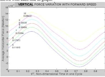
B. Effect of Forward Speed
The effect of forward speed on lift, thrust and drag forces is shown in fig. 9, 10 and 11 respectively. The forward speed has been varied from 5 m/s to 10 m/s while other parameters are kept constant. The lift and drag forces
increase with increase in forward speed but the thrust decreases. It happens so because the aerodynamic force tilts backwards as increase in the forward speed reduces the effective angle of attack. The thrust becomes negative at higher a speed which means the forward speed is limited to a certain value. Forward speed and the total force values are shown with each line in graph.
Fig. 9 Variation in Lift with Forward Speed
Fig. 10 Variation in Thrust with Forward Speed
Fig. 11 Variation in Drag with Forward Speed
C. Effect of Flapping Frequency
pronounced. However, thrust and drag increase rapidly with increase in flapping frequency. The reason is that with increase in flapping frequency, the magnitude of total aerodynamic force increases but when resolved in vertical force it has positive and negative values for down stroke and up stroke respectively. So the effect is not prominent for lift but thrust component of aerodynamic force is always in forward direction and hence marked effect can be observed. Same is true for drag.
Fig. 12 Variation in Lift with Flapping Frequency
Fig. 13 Variation in Thrust with Flapping Frequency
Fig. 14 Variation in Drag with Flapping Frequency
D. Effect of Incidence Angle
The effect of Incidence Angle. Effect of change in incidence angle (0o to 12o) on lift, thrust and drag are shown in fig. 15, 16 and 17. Increase in incident angle increases all the forces. Lift is almost zero at zero incidence angle,
because the flapping is symmetrical and the vertical components of aerodynamic force cancel each other in down and up stroke. However, the thrust and drag are not zero, at zero incidence angle, as these components of aerodynamic force add in each stroke.
Fig. 15 Variation in Lift with Incidence Angle
Fig. 16 Variation in Thrust with Incidence Angle
Fig. 17 Variation in Drag with Incidence Angle
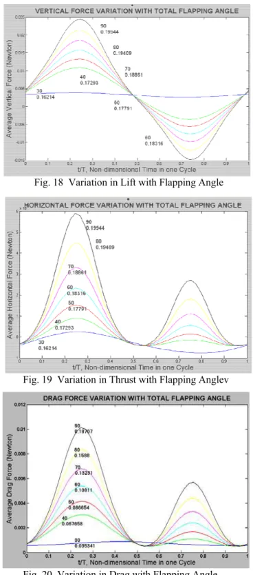
E. Effect of Total Flapping Angle
Fig. 18 Variation in Lift with Flapping Angle
Fig. 19 Variation in Thrust with Flapping Anglev
Fig. 20 Variation in Drag with Flapping Angle
V. CONCLUSION
Although there are endless possibilities of varying the inputs and getting the results in different forms but effect of only few variable design parameters has been presented here for fixed size and geometry of wings for an ornithopter. It can be concluded from this study that:-
a. Lift of an ornithopter is most influenced by the incidence angle and forward speed but least affected by flapping frequency.
b. Thrust of an ornithopter is most affected by flapping frequency and forward speed but least influenced by incidence angle.
c. The drag force increases with increase in forward speed, incidence angle, and flapping frequency. d. The increase in total flapping angle, increases all the
forces but the effect is marked on drag force.
ACKNOWLEDGMENT
The authors are indebted to the National University of Sciences and Technology (NUST), and the NUST College of Electrical and Mechanical Engineering for having made this research possible. We are also thankful to Higher Education Commission of Pakistan and Pakistan Science Foundation for sponsoring this research.
REFERENCES
[1] B-J Tsahi, Y-C Fu, “Design and Aerodynamic Analysis
of Flapping Wing Micro Air Vehicle ”, Aerospace
Science and Technology 2009, AESCTE-2474
[2] International Micro Air Vehicle Competition, to be held on 6-8 Jul 2010 at Braunschwieg, Germany. “http://www.imav2010.org/Mission_Discription_and_R ules_IMAV_2010.pdf”, accessed on 25 January 2010 [3] Ho, Hany Nassel, Nick Pornisinsirirak, Yu-Chong Tai
and Chih-Ming Ho, “Unsteady Aerodynamics and Flow Control for Flapping Wing Flyers” Progress in Aerospace Sciences 2003, Vol. 39, pp 635-681. [4] Alexander, D.E., “Nature’s Flyers”, Johns Hopkins
University Press, Baltimore, 2002.
[5] Shyy, W., Lian, Y., Tang, J., Viieru, D., Liu, H., “
Aerodynamics of Low Reynolds Number Flyers.” , Cambridge University Press, New York, NY, 2008.
[6] Azuma. A, “The Biokinetics of Flying and Swimming”,
AIAA, Reston, VA USA.
[7] Leishman, J. G., Principles of Helicopter
Aerodynamics, New York: Cambridge University
Press, 2000.
[8] DeLaurier, J.D., “An Aerodynamic Model for Flapping Wing Flight,” The Aeronautical Journal of the Royal Aeronautical Society, April 1993, pp. 125-130.
[9] Hirotaka Natsume, “Experimental Study of High Propulsive Efficiency of Three Dimensional Flapping Wing”, Kyushu University, Fukuoka, Japan.
[10]Mueller, T.J., “Fixed and Flapping Wing Aerodynamics
for Micro Air Vehicle Applications”, Reston, VA:
AIAA, 2001.
[11]Robyn Lynn Harmon, “Aerodynamic Modeling of a Flapping Membrane Wing Using Motion Tracking
Experiments” Master’s Thesis 2008, University of
Maryland.
![Fig. 4 Front view of Flapping Wings [11]](https://thumb-eu.123doks.com/thumbv2/123dok_br/17217117.243697/2.892.476.828.766.963/fig-view-flapping-wings.webp)
![Fig. 6 Relative Flow of Air [11]](https://thumb-eu.123doks.com/thumbv2/123dok_br/17217117.243697/3.892.69.438.144.484/fig-relative-flow-air.webp)