Power management of Supercapacitors
using Multi boost and Full Bridge
Converters Used in Electric / Hybrid
Electric Vehicle
*E.GEETHA REDDY, G.SRINIVASA RAO, G.KESAVA RAO, S.SIVANAGARAJU, AND
K.SRINIVASA REDDY
Department of Electrical and Electronics Engineering, Vignan’s University, Vadlamudi, Guntur
*Gita_evuri@yahoo.co.in, srinivas_gorantla@rediffmail.com, deanvoice@yahoo.co.in, sirigiri70@yahoo.co.in,reddy.sinu2003@gmail.com
Abstract-
The Hybrid electric vehicle (HEV) has become one of the most promising vehicles in the automobile industry due to its energy saving ability and low emission of harmful pollutants. Battery management system, which has acceptable life cycle, remains the major roadblock to large-scale production of Electric vehicles and Hybrid electric vehicles, which consists of high power density batteries. This paper emphasis more on the management of the energy provided by super capacitor Packs. Each super capacitors module is made of 108 cells with a maximum voltage of 270V. The multi boost and multi full bridge converter topologies are tested to define the best topology for the embarked power management.. The experimental and simulated results validate the proposed two converter topologies presented in this paper.
Key words: Power management, super capacitors, multi boost and full bridge converters, Hybrid Electric
Vehicle
I.INTRODUCTION
study of different topologies for supercapacitor handling. An in-depth report on control strategies and optimizations are Andersson and Groot (2003) M.Sc thesis report “Alternative Energy Storage System for Hybrid Electric Vehicles”. The work “Comparison of Simulation Programs for Supercapacitor Modeling” by Andersson and Johansson (2008) has also been a useful resource for modeling of the supercapacitor. Doerffel (2007) have studied the ageing and deteriation processes of lithium-ion batteries, and how to measure the state of health.
II.ENERGY STORAGE UNIT
The energy storage unit (ESU) in a car handles the storage of the electrical energy and functions as a buffer for the electrical machine (and the generator in the series hybrid configuration). The ESU has the possibility to either receive or deliver power from or to the electrical machine (via a DC/AC inverter). Depending on application and dimensioning parameters, such as hybridization level and size of the vehicle, is it possible to configure the ESU in different combinations. It is necessary to have a storage utility, which could be a battery or a supercapacitor or a combination of the both, to work as the source of energy and power In this thesis work, a combination consisting of a supercapacitor in parallel with a battery will be studied. If there is a need to control the power flow or if there is a need to have different voltage levels (i.e. the voltage over the capacitor is dimensioned to be lower than the voltage over the battery or vice versa) it can be possible or necessary to install a converter in series with the battery or the supercapacitor or both. If the converter is installed in series with the battery it is possible, with the ability of power control, to get a direct control over the power to the battery. Another possible combination is to install two converters, one in series with the supercapacitor and one in series with the battery, but this would lead to an unnecessary complexity of the system. Therefore, in this paper , a converter has been installed in series with the supercapacitor. The configuration is presented in
Figure-2.1.
Figure2.1 Overview of energy storage unit Battery
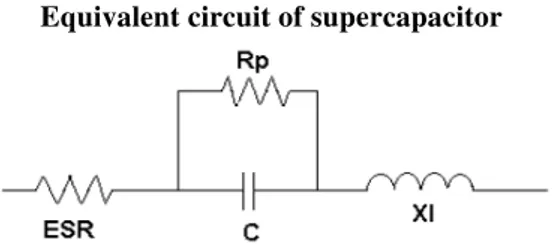
Equivalent circuit of supercapacitor
Figure2.2 Supercapacitor equivalent circuit
This equivalent circuit is only a simplified or first order model of a super capacitor. This causes super capacitors to exhibit behavior more closely to transmission lines than capacitors. Below is a more accurate illustration of the equivalent circuit for a supercapacitor.
III.PROPOSED BLOCK DIAGRAM
Figure 3.1: Electric vehicle/hybrid electric vehicle system using supercapacitors.
The supercapacitor technology is relatively new, and is constantly evolving.
Power Flow
The load power, coming from the outer parts of the HEV, can be both positive and negative. A positive load power is in this work defined as that there is a surplus of power in the outer system and the power is therefore flowing into the ESU (generator reference). If the load power is negative there is a demand for power in the external system and power is flowing out from the ESU. Inside the ESU the load power is divided between the power to the battery and power to the supercapacitor, which is demonstrated in Figure 3.2.
Figure 3.2 Power flow to the ESU
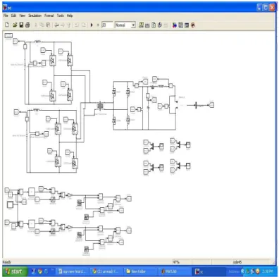
problems in nineties by commercializing the electric vehicle. But the battery weight and cost problems were not solved. The batteries must provide energy and peaks power during the transient states. These conditions are severe for the batteries. To decrease these severe conditions, the super capacitors and batteries associate with a good power management present a promising solution. Simulink, a model is a collection of blocks which, in general, represents a system. In addition, to drawing a model into a blank model window, previously saved model files can be loaded either from the File menu or from the MATLAB command prompt.
Figure 3.3(a) Multiboost converter topology
Figure3.3 (b)Multi full bridge converter topology
IV Simulation & Experimental Results:
4.1 Full bridge converters experimental results
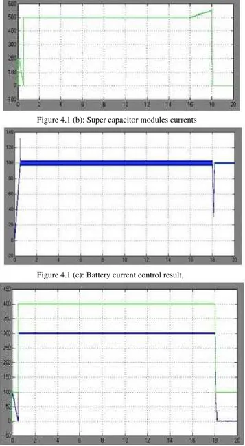
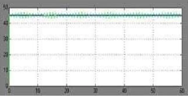
The simulation has been made for Np = 2. The maximum and minimum voltages of the Super capacitor modules are respectively fixed at 270V and 135V. The hybrid vehicle requested Current (Ich) is respectively fixed at 100A from 0 to 0.5s, 400A from 0.5s to 18s and 100A from 18s to 20s. Battery reference current (Ibatref) is fixed at 100A independently of the hybrid vehicle power Request.
Super capacitor modules voltages (Vsc1, Vsc2) presented in Fig.4.1 (a) are identical. The currents amplitudes (Isc1, Isc2) presented in Fig.4.1 (b) are also identical. Control enables to maintain the battery current (Ibat) at 100A; but around 0.5s and 18s the battery current control loop has not enough time to react Fig.4.1 (c). The important power of the transient states is ensured by the super capacitors modules
(IL) Fig.4.1 (d).
Figure 4.1 (b): Super capacitor modules currents
Figure 4.1 (c): Battery current control result,
Figure 4.1 (d): DC-link and active load currents
4.2 Boost converters simulation and experimental results
The boost converters experimental test is carried out in the following conditions: During the super capacitors discharge, the batteries current reference (Ibatref) is fixed at 13A so that, the supercapacitors modules provide hybrid vehicle power request during the transient states. For these tests, the hybrid vehicle request (Ich) was fixed at 53A.
The experimental and simulations results of the modules voltage are compared in Fig.4.2 (a) and Fig.4.2 (b). The (Isc1) and (Isc2) experimental currents are not identical Figure 4.2(c) & (d) because the super capacitors dispersion and the power electronic circuits (boost converters) inequality.
The first boost converter ensures 50% and the second ensures also 50% of the DC-link current
Figure 4.2 (a) & (b). Super capacitor modules experimental and simulation voltage results
Figure 4.2 (a) First module voltage
Figure 4.2 (b) Second module voltage
Figure 4.2 (c) & (d). Super capacitor modules experimental and simulation current results
Figure 4.2 (d) Second modules current
Figure 4.2 (e) & (f). DC-link voltage and current experimental validation
Figure 4.2 (e) Multi boost output current (IL )
Figure 4.2 (f) Battery current experimental result
4.3 Full bridge converters experimental results
The super capacitors power is not constant (Vsc1, Isc1) because of the consumed current by R1,R2, R3 and R4 resistances Fig.4.3 (b). The battery current experimental result is presented in Fig.4.3 (c). The voltages and currents ripples which appear in Fig. 4.3 (b), Fig.4.3 (b) and Fig. 4.3 (c) are caused by leakage inductances of the transformer and wiring of the power electronics devices. Figure 4.3 (d): High frequency planar transformer voltages and currents (e) Transformer input and output voltages
Figure 4.3. (b): Super capacitors module voltage and current
Figure 4.3(c): DC-link and active load experimental currents
Figure 4.3 (d): High frequency planar transformer voltages and currents (e) Transformer input and output voltages
Figure 4.3 (d): High frequency planar transformer voltages and currents
Hardware Requirements
Conclusion
In this paper, multi boost and multi full bridge converter topologies and their control strategies for batteries and super capacitors coupling in the hybrid vehicle applications were proposed. The system control is ensured by PIC18F4431or AT89C51 microcontroller’s type which includes 9 analog inputs and 8 PWM outputs.For reasons of simplicity and cost, the multi boost converter is the most interesting topology regarding the multi full bridge converter topology. It enables a good power management in hybrid vehicle.Full bridge experimental tests conditions were different from that of boost converter topology, so at this time it is not easy to make a good comparison between the two topologies.However, multi full bridge converter topology is well suitable to adapt the level of available voltage to the DC-link. For low voltage and high current applications such as super capacitors, the full bridge converter seems to be less interesting because of its higher cost ( many silicon and passive components), and a lower efficiency.
BIBLIOGRAGHY
[1] J.M Timmermans, P. Zadora, J. Cheng, Y. Van Mierlo, and Ph. Lataire. Modelling and design of super capacitors as peak power unit for hybrid electric vehicles. Vehicle Power and Propulsion, IEEE Conference, 7-9 September, page 8pp, 2005.
[2] Huang jen Chiu, Hsiu Ming Li-Wei Lin, and Ming-Hsiang Tseng. A multiple- input dc/dc converter for renewable energy systems. ICIT2005, IEEE, 14-17 December, pages 1304–1308, 2005.
[3] M.B. Camara, H. Gualous, F. Gustin, and A. Berthon. Control strategy of hybrid sources for transport applications using supercapacitors and batteries. IPEMC2006, 13-16 August, Shanghai, P.R.CHINA, 1:1–5, 2006.
[4] L. Solero, A. Lidozzi, and J.A. Pomilo. Design of multiple-input power converter for hybrid vehicles. IEEE transactions on power electronics, 20, Issue 5, 2005.
[5] Xin KONG and A. KHA. Analysis and implementation of a high efficiency, interleaved current-fed full bridge converter for fuel cell system. IEEE, 28-01 Nov, 1:474–479, 2005.
[6] M.B. Camara, F. Gustin, H. Gualous and A. Berthon. Studies and realization of the buck-boost and full bridge converters with multi sources system for the hybrid vehicle applications. Second European Symposium on Super capacitors and Applications,ESSCAP2006, Lausanne, Switzerland,2-3 November, 2006.
[7] Huang-Jen Chiu, Hsiu-Ming, Li-Wei Lin, Ming-Hsiang Tseng. A Multiple-Input DC/DC Converter for Renewable Energy Systems, Industrial Technology, ICIT2005, IEEE international Conference, 14-17 December 2005, Pages:1304-1308
[8] LOUNIS Zohra. APPOTS DES TECHNIQUES DE CABLAGES LAMINAIRES DANS UN ONDULEUR A IGBT DE MOYENNE PUISSANCE. PhD thesis, Institut National Polytechnique de Lorraine, 2000.
[9] Seong-Jeub Jeon, Gyu-Hyeong Cho. A Zero-Voltage and Zero-Current Switching Full Bridge DC-DC Converter With Transformer Isolation, IEEE Transactions on power Electronics, Vol.16, No.5, September 2001, Pages:573-580
[10] Yungtaek Jabg, Milan M.Jovanovic, Yu-Ming Chang. A New ZVS-PWM Full-Bridge Converter, IEEE Transactions on power Electronics, Vol.18, No.5, September 2003, Pages:1122-1129.
AUTHORS:
*Mrs.E.Geetha Reddy Graduated from MIST, sathupally, in Electrical & Electronics Engineering. Now pursuing Masters in Power Electronics and Drives (PED) from Vignan University,Vadlamudi,Guntur.
Gorantla Srinivasa Rao received his B.Tech in Electrical and Electronics Engineering from Acharya Nagarjuna University, India in 1998 and ME (High Voltage Engineering) from Guindy College of Engineering, now known as Anna University in India in 2001. He is currently working at Vignan University, Vadlamudi, India. as an Associate Professor and Faculty Advisor to student chapter of Indian Society for Technical Education (ISTE). He has about 18 publications in National and International Journals and Conferences to his credit. His research interests include power system automation, hybrid vehicle design and reactive power compensation.
S.Sivanagaraju received his Masters in 2000 from the IIT,Kharagpur, and he did PhD at the JNT University in 2004. He is working as an associate professor in the department of Electrical Engineering, JNTU College of Engineering(autonomous), Kakinada. He is a Referee for IEEE Proceedings – Generation Transmission and Distribution and International Journal of Emerging Electric Power System . he has about 40 publications in national and international journals and conferences to his credit. His areas of interest are in distribution automation genetic algorithm applications to distribution systems hybrid vehicle design and power system
K. Srinivasa Reddy is Associate Professor of the Electronics and Communication Engineering, Nagole
Institute of Technology and Science,Hyderabad .He received his B.Tech degree in Electronics and
Communication Engineering from JNT University, Hyderabad, and M.Tech degree in Embedded Systems from JNT University, Hyderabad.. He is a member of The International Association of