ISSN 1549-3636
© 2010 Science Publications
Corresponding Author: Anas F. Bayan, National Advanced IPv6 Centre (Nav6), University Sains Malaysia, 11800 Penang, Malaysia Tel: +604-653 3005 Fax: +604-653 3001
Delay Analysis and System Capacity Control for Mobile
WiMAX Relay Networks
1
Anas F. Bayan,
1,2Tat-Chee Wan and
1Sureswaran Ramadass
1
National Advanced IPv6 Centre of Excellence (NAv6),
2
School of Computer Sciences,
University Sains Malaysia, 11800 Penang, Malaysia
Abstract: Problem statement: WiMAX relay is an emerging cost effective wireless last mile solution
for rural and urban broadband Internet access. Approach: One of the key concerns of WiMAX operators is how many users they can support for an access area where the number of users and the amount of data that can be delivered to the end user depends on the available system capacity.
Results: This scenario is even more complex when multi-hop relays are introduced into the network
whereas the user access capacity decreases with the increase of hop number. Therefore, to maintain and satisfy QoS demands from various users in a multi-hop relay network, it is essential to control and determine the number of users connect to each zone in regards to different levels of QoS. In this study a system capacity control technique was presented for IEEE 802.16j relay network to control the number of users that connect to the network and calculate the system capacity in terms of a three level relay topology. We presented a simple mathematical analysis of the proposed technique as well as delay analysis of the relay network. Conclusion/Recommendations: The analytical results showed that the proposed technique has achieved the objective of this study. Controlling and determining the number of user is very crucial in order to maximize the throughput for each individual user requirement of QoS, maintain fairness between users in the networks and guarantee QoS for real time application users.
Key words: WiMAX, IEEE 802.16j, QoS, throughput, delay
INTRODUCTION
Providing seamless information access via wireless links to end users over a geographically large area is an important goal for wireless communications technology. However, it is challenging to deploy broadband wireless access for sparsely populated rural areas, non line of sight coverage in urban environments, in-building coverage as well as addressing coverage holes where there is limited or no backhaul connectivity due to geographical barriers, greater geographical distance, limited resources and expensive backhaul requirements. Consequently, WiMAX enabled multi-hop relay (IEEE Std 802.16j-2009, 2009) has been standardized to address the connectivity problems found in single Base Station (BS) based WiMAX configurations.
This standard is compatible with the previous IEEE Std 802.16e-2004 (2004) and IEEE Std 802.16e-2005 (2006). Therefore, traditional WiMAX clients will work normally in a Mobile Multi-hop Relay (MMR) enhanced infrastructure.
The use of WiMAX relays would extend the range and coverage of rural areas, increase the
capacity of a wireless system as well as improve the penetration of WiMAX signals into the indoor environment (Genc et al., 2008a). Furthermore, since Relay Station (RS) works as link layer repeater, a wired backhaul is not needed in the relay.
1138
Table 1: Transparent and non-transparent relay
T-RS NT-RS
Only relays data traffic to the BS and vice versa Operate as a BS for the SS
Operate in centralized scheduling Operate in distributed or centralized scheduling
Operate for topology up to two hops Operate in topology larger than two hops
Does not have scheduling capabilities Have scheduling capabilities
Does not transmit preamble nor broadcast control message Transmits a DL frame start preamble, FCH and MAP messages
Improve intra-cell throughput Improve throughput and coverage extension
Communication using the same carrier frequency Communication using the same or different carrier frequencies
Does not participate in bandwidth allocation Participate in bandwidth allocation in distributed scheduling mode
Furthermore, it is important to highlight that the capacity of WiMAX system depends on environmental conditions, WiMAX channel configurations and types of applications being used. The channel size can vary with time as environmental conditions change and WiMAX operators may configure WiMAX channel in different ways based on operator preferences, regulatory constraints and performance requirements (SR Telecom, 2006).
The focus of this study is on the system capacity control and delay of a WiMAX relay system. We present a system capacity control technique for IEEE 802.16j relay network to control the number of users that connect to the network and calculate the system capacity in terms of a three level relay topology as well as delay analysis for the relay network.
RS working schemes: MMR WiMAX network
consists of three network entities called Multi-hop Relay Base Station (MR-BS), RS and Mobile Stations (MSs)/Subscriber’s Stations (SSs). These three network entities define the hierarchical tree topology of MMR network where the MR-BS is at the root of the tree. RSs functionality is to work as intermediate node between MR-BS and SSs/MSs. Thus, it relays the information between SSs/MSs and a MR-BS or between RS and a MR-BS. RS may work in three possible schemes depending on how the received signals are processed (Soldani and Dixit, 2008).
These schemes are:
• Amplifying and Forwarding (AF): The relay node amplifies and retransmits the received week signals (which loses its strength gradually and carrying the receiver noise). Therefore, increasing the system noise level.
• Decoding and Forwarding (DF): The relay extracts the information from the received modulated signal and translates it into intelligible (interpretable) format before retransmission.
• Estimating and Forwarding (EF): The relay node does not translate the input data but it subdivides the received signal (without decoding), then source codes the signals and finally transmits it to the destination
Centralized and de-centralized controlled relaying
approach: RS is less complex than BS because it does
not need to provide backhaul functionality as a BS does. Multi-hop communications in MMR can be coordinates in either centralized or de-centralized approach. In centralized controlled approach, the BS has full control over all the network entities (RSs and SSs), where all the RSs and SSs are controlled directly by the BS. The RS does not perform any MAC management functions to allow for multi-hop communications, but its only forwards the packets from one hop to another hop. Therefore, the complexity of the RS consider less than the BS. In decentralized controlled approach, the RS has full control over all the SSs connects to it. The RS has the ability to perform multi-hop operation as it’s encapsulated the whole functionality required for multi-hop communications. The BS is not affected. Hence, a RS occur as a normal SS for the BS and appear as regular BS for the SSs. The RS build its MAC frame. This frame is called multi-hop sub-frame which is a standard conforming to requirements of 802.16 MAC frame.
Transparent and non-Transparent relay operating
modes: Based on the physical processing perspective
RSs are classified into two modes, Transparent Relay Station (T-RS) and Non-Transparent Relay Station (NT-RS). Table 1 shows the key difference between transparent and non-transparent operation mode (Masato et al., 2008; Nie et al., 2008).
RS usage models: In IEEE 802.16j network, the
Internet Service Provider (ISP) may deploy RSs for different reasons (Marks, 2006). Listed below are the possible reasons that ISP might deploy RSs:
• Enhanced data rate coverage: This can be achieved by providing higher uniform Signal to Interference and Noise Ratio (SINR) to the users within the MMR cell coverage. In other words, this can also be done by providing higher throughput to individual MSs within the MMR cell coverage
where the SINR is low and limited for instance, rural area or outskirts area, RSs are deployed to extend the coverage area beyond the perimeter of the BS coverage
• Capacity enhancement: Increased the system capacity can be achieved by allowing aggressive frequency reuse within the BS cell and by enhancing the SINR where the SINR is limited. Thus RSs are deployed to increase the system capacity to high load regions within the BS cell. Where RS might be deployed individually or in clusters around the perimeter of the BS cell according to the needed capacity
Types of RS: RS can be defined as Fixed, Nomadic or
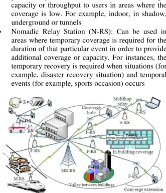
Mobile RS to suit different deployment scenarios or usage models. These RS is use for the system performance enhancement by allowing coverage extension and increasing the throughput. In certain scenario, the ISP may choose different types of RS to be deployed according to the topology, traffic and mobility within the surrounding area of each RS location. Hence, in such MMR network each usage scenario might include multiple RS types and multiple usage models (Marks, 2006; Jerry, 2006) the most important RS types and Usage scenarios are shown in Fig. 1:
• Fixed Relay Station (F-RS): Is installed permanently at fixed location to enhance coverage, capacity or throughput to users in areas where the coverage is low. For example, indoor, in shadow, underground or tunnels
• Nomadic Relay Station (N-RS): Can be used in areas where temporary coverage is required for the duration of that particular event in order to provide additional coverage or capacity. For instances, the temporary recovery is required when situations (for example, disaster recovery situation) and temporal events (for example, sports occasion) occurs
Fig. 1: RS types and usage models
• Mobile Relay Station (M-RS): Is fully mobile and can be mounted on moving vehicles such as train, bus or car and get connected to an MR-BS or RS through mobile link
Mesh Vs multi-hop relay: In WiMAX, multi-hop
communications could occur in mesh operation mode and in MMR networks by installing RS that allow for multi-hop communications. In MMR networks, multihop communications between users and the MR-BS occurs when the client are out of the MR-BS range and coverage but in the range of a RS, to connect the users to the network via RSs. While in mesh mode, multi-hop communications between users and the BS occurs via SS. Figure 2 shows the key difference between mesh and MMR networks.
Study on the optimal number of hops in MMR
networks: In a multi-hop relaying network with fixed
relay station, the relay station consider as part of the network infrastructure. As we mentioned earlier, the RS functionalities are to extend the coverage range, increase the capacity, reduced the dead spots and improve the overall services in the network. One of the most important aspects in deploying wireless multi-hop relay with the use of fixed relay stations is to define the optimal number of hops along the path between the source and the destination. Therefore, the number of hops (RSs) in the network must be carefully considered.
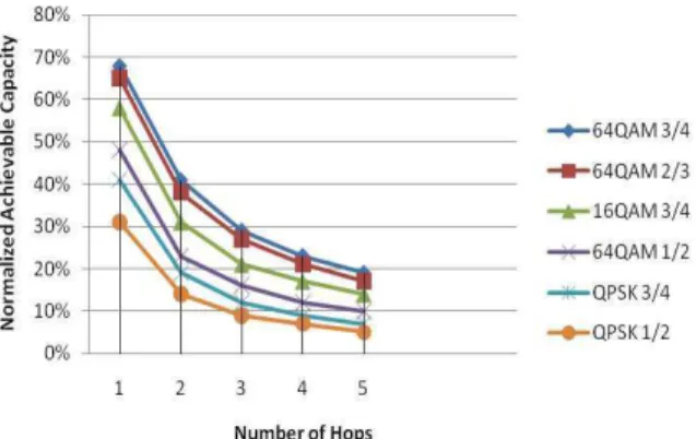
Research work done by Wei (2007) has indicated that by increasing the number of hops (RSs) in WiMAX multi-hop relay system, the achievable client access capacity decreases dramatically. Wei (2007) has also proposed that the achievable access capacity can be enhanced by using higher level modulation schemes or higher turbo coding rate respectively. Figure 3 shows normalized achievable capacity for each number of hops using different type of modulation and coding schemes.
1140 As shown in Fig. 3, when the number of hop is one and 64QAM-3/4 is used, 68% of the whole capacity can be allocated for user access while when the number of hop is two, 41% of the whole capacity can be allocated for user access. For three hops, only 29% of the whole capacity can be allocated for user access. From the Fig. 3, we can interpret that the achievable user access capacity can be significantly improved by using higher level modulation scheme or higher turbo-coding rate. For example, when the number of hops is two and 64QAM-3/4 is used, the achievable access capacity can reach 41% compared to 14% when using QPSK-1/2.
Figure 4 shows an example of total amount of traffic transported at each hop or at wireless relay link. We assume the traffic load is identical at each hop, n represent number of hops which is three hops and X represents the traffic load at each hop.
At hop F-RS3, local traffic is X so the amount of traffic transported at the wireless relay link between FRS2 and F-RS3 will be X. The total amount of traffic transported at previous two hops which is between FRS1 and F-RS2 will be 2X. For wireless relay link between the BS and F-RS1, the amount of traffic transported will be 3X.
Fig. 3: Normalized achievable capacity versus number of hops (Wei, 2007)
Fig. 4: Example of amount of traffic at wireless relay link
From Fig. 4, we conclude that by increasing the number of hop, the total amount of traffic to relay increased respectively. Thus, bottleneck might be occurred at F-RS1.
Based on (Wei, 2007; Deb et al., 2008; Genc et al., 2008b) the maximum number of hops recommended to be used in MMR network is not more than three hops to guarantee that there’s sufficient capacity for the local client to access the network. Therefore, we assume that the maximum number of hops recommended is based on these studies.
Increasing the number of hops per connection might result to higher delay and affects the bandwidth efficiency. It’s not recommended to use centralized scheduling mode if the number of hops > 3 (Zhou, 2008).
MATERIALS AND METHODS
Network topology: Figure 5 shows an envisioned
linear multi-hop relay topology of IEEE 802.16j consisting of one MR-BS, three F-RS, MSs and fixed SSs. MSs and SSs may connect directly to the base station if it is in the coverage area of the MR-BS otherwise, it will be connected to the network and get the services through the F-RS which is installed as fixed relay stations in order to enhance the coverage and capacity of the MR-BS.
System capacity control analytical model:
Controlling and determining the number of user is very crucial in order to maximize the throughput for each individual user requirement of QoS, maintain fairness between users in the networks and guarantee QoS for real time application users. The more users connect to the network, the more traffic congestion toward the MR-BS. Therefore, the system capacity control technique presented as a solution to control the number of users that connect to the network and calculate the system capacity in terms of a three level relay topology. For better QoS and resource utilization, Total Traffic (TF) at BS must be less than or equal to the MR-BS capacity. Equation 1 used to calculate total traffic at each level (wireless zone):
j j
r
n m
j j j j 1
i 0 r 0 TF at Hop U i TF+
= =
=
∑
+∑
(1)Where, j∈ |0, L|: L = Layer
(nj) = Number of users at level j
In Eq. 2 we show how to calculate total traffic load in the network at the MR-BS for a three level relay topology:
n m n m n m n
0 0 1 2 3
i 0 r 0 i 0 r 0 i 0 r 0 i 0
TF U U U U
= = = = = = =
=∝
∑
+ ∝∑∑
+ ∝∑∑
+ ∝∑∑
(2)U = The traffic load per user
n = Number of users
m = Number of relays
(∝0, ∝1, ∝2 ∝3) = Control parameter for each level:
3
0 0 j
j 1
TF m nu BS capacity
=
= ∝ + ∝ ≤
∑
(3)We define the system capacity in Eq. 3 in terms of a three level relay topology where the QoS for individual users are constrained by the variables ∝0, ∝1,
∝2 ∝3 at the respective levels. ∝, is a fraction less than
one of the total BS capacity.
Delay analysis: For a traffic flow traversing the
network and during the connection setup with the MR-BS, a MS/SS send the expected delay/negotiated delay constraint with a set of QoS parameters to the MR-BS. To calculate the experienced delay/actual delay let D(i,k)
Eq. 4 denote the delay of the (i) packet for the (kth) hop. Therefore, we define the per hop traffic flow delay as in the following Eq. 4-8:
(i,k ) k q (i,k )
D =D +D (4)
k proc prop trans
D =d +d +d (5)
prop s s d
prop
= (6)
trans PL d
TR
= (7)
( i ,k ) ( i ,k ) ( i ,k )
q tx rx
D =t −t (8)
Fig. 5: Network topology
where, Dk represent constant delay at a single hop (k)
due to the processing delay (dproc), propagation delay
(dprop) and transmission delay (dtrans). Processing delay
is the time that a hop spends processing a packet, this comprise error checking time, reading the packet header time and time for finding the link to the next hop. Propagation delay is the time that it takes a signal change to propagate through the communication media from a hop to the next hop. It can be calculated using Eq. 6 where (s) is the distance between hop and the next hop and (props) is the propagation speed. Transmission
delay is the time required for the packet to be in the transmission media for transmission it can be calculated using Eq. 7 where, (PL) is the packet length in bits and (TR) is the transmission rate in bits per time unit.
(i ,k ) q D
represent the queue delay of the (i) packet at (k) hop. (i ,k )
rx
t and ( i ,k ) tx
t in Eq. 8 respectively represent the reception and transmission time of the (i) packet at the (k) hop. The Accumulated Delay (AD) of the (i) packet for multi-hop (h) where (h) represent the number of hops defined as in Eq. 9:
h h
(i ) (i, k ) k q (i,k )
k 1 k 1
AD D hD D
= =
=
∑
= +∑
(9)
RESULTS AND DISCUSSION
The control parameter ∝ is used as a fixed control parameter for controlling the number of users connected to each wireless zone. Where it is used to accept or reject users at each relay in accordance with the predefined number of users (n) allocated for each relay on the network while maintaining the QoS for each tier. Consequently, users request can be accepted or rejected based on its required QoS parameters, total network capacity (available bandwidth) and already accepted flows.
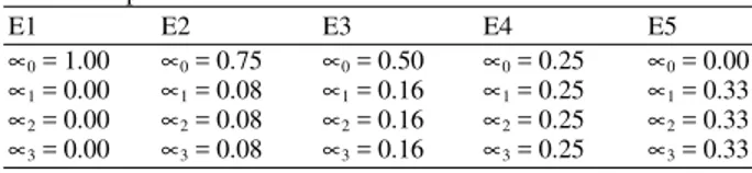
Figure 6 shows the impact of the system capacity control technique on controlling the number of users connected to the network and enhances the system capacity for each number of relays by using different control parameters of ∝ Table 2 as fixed control parameter. As a result, the optimal number of users per relay is 25 users. Whereas at the BS, the impact on the number of users was high compared with the relays, different control parameters shows different results on user’s number.
Table 2: Various values of ∝ at the respective level for each
experiment
E1 E2 E3 E4 E5
∝0 = 1.00 ∝0 = 0.75 ∝0 = 0.50 ∝0 = 0.25 ∝0 = 0.00
∝1 = 0.00 ∝1 = 0.08 ∝1 = 0.16 ∝1 = 0.25 ∝1 = 0.33
∝2 = 0.00 ∝2 = 0.08 ∝2 = 0.16 ∝2 = 0.25 ∝2 = 0.33
1142 Fig. 6: Maximum number of users (n) per relay to
satisfy Eq. 3 for various values of ∝
CONCLUSION
This study presents a new system capacity control technique and delay analysis for IEEE 802.16j relay network. The system capacity is determined by the number of users distributed in the service area and the requested type of service. The analytical result shows that the system capacity control technique enhanced the achievable number of user’s access per relay and the overall system capacity. To ensure QoS, total traffic load at any level must be less than or equal to the BS capacity as well as the maximum number of hops recommended for a MMR network is not more than three hops to guarantee sufficient capacity for local clients to access the network. The analytical model can be used for validation of simulation models. Further studies will be focused on the dynamic control of user’s number at each level.
ACKNOWLEDGMENT
The authors would like to acknowledge University Sains Malaysia (USM) and Institute of Postgraduate Studies (IPS), USM for funding of USM Fellowship Scheme 2009/2010, Postgraduate Research Grant Scheme (USM-RU-PRGS) and USM Short-term Grant Scheme.
REFERENCES
Chakchai, S.I., R. Jain and A.K. Tamimi, 2010. Capacity evaluation for IEEE 802.16e mobile WiMAX. J. Comput. Syst. Networks Commun., 2010:1-12. DOI: 10.1155/2010/279807
Deb, S., V. Mhatre and V. Ramaiyan, 2008. WiMAX relay networks: Opportunistic scheduling to exploit multiuser diversity and frequency selectivity. Proceeding of the 14th ACM International Conference on Mobile Computing and Networking, ACM Press, Sept. 14-19, San Francisco, California, USA., pp: 163-174. DOI: 10.1145/1409944.1409964
Genc, V., S. Murphy and J. Murphy, 2008a. Performance analysis of transparent relays in 802.16j MMR networks. Proceeding of 6th International Symposium on In Modeling and Optimization in Mobile, Ad Hoc and Wireless Networks and Workshops, Apr. 1-3, IEEE Xplore Press, Berlin, pp: 273-281. DOI: 10.1109/WIOPT.2008.4586077
Genc, V., S. Murphy, Y. YU and J. Murphy, 2008b. IEEE 802.16J Relay-based wireless access networks: An overview. IEEE Wireless Commun.
Mag., 15: 56-63. DOI:
10.1109/MWC.2008.4653133
IEEE Std 802.16e-2004, 2004. IEEE standard for local and metropolitan area networks part 16: Air interface for fixed broadband wireless access systems. IEEE Computer Society. DOI: 10.1109/IEEESTD.2004.226664
IEEE Std 802.16e-2005, 2006. IEEE standard for local and metropolitan area networks part 16: Air interface for fixed and mobile broadband wireless access systems amendment 2: Physical and medium access control layers for combined fixed and mobile operation in licensed bands and corrigendum 1. IEEE Computer Society. DOI: 10.1109/IEEESTD.2006.99107
IEEE Std 802.16j-2009, 2009. IEEE standard for local and metropolitan area networks part 16: Air Interface for broadband wireless access systems amendment 1: Multiple relay specification. IEEE
Computer Society. DOI:
10.1109/IEEESTD.2009.5167148
Jerry, S., 2006. Harmonized contribution on 802.16j (mobile multihop relay) usage models. IEEE
802.16 Relay Task Group.
http://www.ieee802.org/16/relay/docs/80216j-06_015.pdf
Marks, R., 2006. 802.16j (mobile multihop relay) usage models. IEEE Press.
http://www.ieee802.org/16/relay/contrib/C80216j-06_026.pdf
Masato, O., C. Zhu and D. Viorel, 2008. Multihop Relay extension for WiMAX networks-overview and benefits of IEEE 802.16j standard. Fujitsu Sci.
Tech. J., 44: 292-302.
Nie, C., T. Korakis and S. Panwar, 2008. A multi-hop polling service with bandwidth request aggregation in IEEE 802.16j networks. Proceeding of the IEEE Vehicular Technology Conference, May 11-14, IEEE Xplore Press, Singapore, pp: 2172-2176. DOI: 10.1109/VETECS.2008.485
Soldani, D. and S. Dixit, 2008. Wireless relays for broadband access. IEEE Commun. Mag., 46: 58-66. DOI: 10.1109/MCOM.2008.4463772
SR Telecom, 2006. WiMAX capacity white paper. SR Telecom Inc.
http://api.ning.com/files/qOXLHCa9LU6zysMO*i hrbETzfotwj1vAMSkkI1cYpyh8aEP8rMLxUx5Zd UtwjnTk*N1nwU3HbhB48Gs*mDFBYlbFxeMka a5W/WiMAXCapacity.pdf
Wei, Z., 2007. Capacity analysis for multi-hop WiMAX relay. Proceeding of the International Conference on Wireless Broadband and Ultra Wideband Communication, Mar. 2007, University of Technology Sydney, Sydney, pp: 1-4. http://hdl.handle.net/2100/145