*e-mail: [email protected]
1. Introduction
The American Petroleum Institute (API) classiies the steels used in the oil industry according to their application, chemical composition and mechanical strength. Particularly those steels used in the transmission lines (transfer and transport of oil and natural gas) are designated as API 5L1. Besides the weldability, the materials that meet the above-mentioned standard should combine a high mechanical strength with a good toughness. The microalloyed steels fulill these requirements due to the effects of hardening and strengthening promoted by precipitation, solid-solution, and grain reinement that can occur during their thermomechanical processing2,3. Due to a good control over the processing variables, such as temperature of deformation, strain rate and degree of strain, the controlled rolling allows improvement of the mechanical properties of the microalloyed steels4,5. Microalloyed steels can also be applied in the ore-conveying pipelines; however, the inner wall of the pipe is characterized by a poor wear resistance, when in contact with slurries containinghard abrasive particles, such as hematiteand silica.
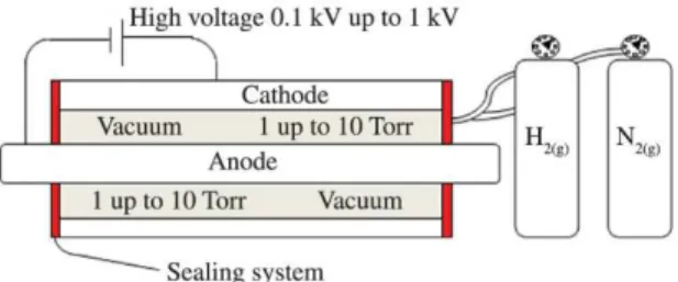
For a number of steel grades, the thermochemical treatment of plasma nitriding allows an effective combination of metallurgical properties, improving the surface hardness, wear resistance, fatigue life, and, in certain cases, corrosion resistancee6. Forworkpieces like pipes, however, plasma nitriding using a traditional arrangement is not possibledue to dificulties associated with the great height and the position of the surfaces (inner wall) to be nitrided. Figure 1 shows schematically a manner by which the inner wall of a steel pipe may be plasma nitrided. In this novel coniguration, the cathode corresponds to the inner surface of the pipe wall to be nitrided, whereas a part placed in the center of the cathodic tube can act as the anode.The concept of nitriding the inner parts
of very long tubes is not new. Wei et al.7 published in 2004 a work describing a process called Magnetic Field Enhanced Plasma (MFEP) for deposition of Si, SiC orDiamond Like Carbon (DLC)coatingsinside stainless steel pipes.
Efforts have been made since the mid-1980s for understanding the behavior of microalloyed steels after plasma nitriding8. Plasma nitriding performed at 450 °C for 10h can promote a signiicant increase in the surface hardness of a microalloyed steel9 and thereby an improvement in its wear resistance. The presence of larger amount of nitride-forming elements in theses steels enables the precipitation of inely dispersed nitrides, resulting in a surface with hardness higher than that of plasma nitrided plain carbon steels. Mahboubi et al.9 showed that the hardening proiles for a microalloyed steel are characterized by having a high surface hardness, small depths and an abrupt hardness transition at diffusion zone, whereas the proiles for a plain carbon steel can reach large hardening depths, but a low surface hardness that decreased slightly towards the core. Basically, two distinct zones are formed on the steel surface after the thermochemical treatment of plasma nitriding: (i) the diffusion layer that appears darker after a chemical etching, and (ii) an upper bright layer referred to as compound layer (or white layer). The latter can be constituted of a mono-phase structure, with the presence of only one type of nitride (γ’-Fe4N or ε-Fe2-3N or alloying nitride), as much as a two-phase or poly-phase structure, comprising of a mixture of different nitrides10-14. Mahboubi and co-workers8 veriied a reduction in the core hardness (softening) when the microalloyed steels are treated at higher temperatures, making them less suitable for nitriding at high temperatures. Lesage et al.15 studying plasma nitriding response of an API 5L X-65 steel, observed that after 16h it is possible to obtain a homogeneous two-phase compound
Improving the Abrasive Wear Resistance of a Microalloyed Steel by Plasma Nitriding
Maria da Conceição Rocha Lima Cesconettoa, Adonias Ribeiro Franco Jr.a*,
Estéfano Aparecido Vieiraa
aCoordenadoria de Metalurgia, Instituto Federal do Espírito Santo – IFES, Campus Vitória,
Avenida Vitória, 1729, CEP 29050670, Vitória, ES, Brazil
Received: August 22, 2014; Revised: March 8, 2015
The aim of this work was to study the micro-abrasive wear resistance of an API 5L X-70 microalloyed steel plasma nitrided under different conditions of time and temperature. Pulsed DC plasma nitriding experiments were performed under a treatment atmosphere of 10%N2 + 90%H2, at temperatures of 410, 440 and 470 °C and for nitriding times of 1, 3 and 5h. The results show that plasma nitriding performed at 440 °C and 1h led to the formation of a compound layer constituted mainly of ε-Fe2-3N nitride and a diffusion zone with large needle-like nitride, offering the highest wear resistance. The amount of γ’- Fe4N phase was found to increase with the plasma nitriding time, decreasing the wear resistance of the material.
layer, constituted of γ´ and ε (traces) nitrides, and a deep diffusion zone containing γ´ needle-like nitride.
The works reported in the literature show that both the growth of nitrided layers and the formation of nitrides are strongly dependent upon the chemical composition of the steel, as well the nitriding conditions, such as temperature, time and atmosphere of the treatment. In addition, there is a lack of data concerning the wear behaviour for all the grades of microalloyed steels, as well the nitriding conditions that allow for the improvement of their wear resistance.The present work provides data about the wear resistance of a microalloyed steel plasma nitrided at different conditions of temperature and time, establishing a nitriding condition that enabled a surface offering the highest microabrasive wear resistance.
2. Experimental Procedure
2.1. Material
Rectangular samples of microalloyed steel (chemical composition, in wt.%: 0.10C - 1.63Mn - 0.15Si - 0.051Nb - 0.035V - 0.019Ti - 0.003Mo - 0.025Cr - 0.16Ni - 0.015Cu - 0.02P - 0.004S) with approximately 3 cm in length, 2 cm in width and 4 mm in thickness were prepared at IFES laboratories from an API 5L X-70 pipe, which measured 24” in diameter and 0.812” in wall thickness. The pipe was manufactured by Tenaris Confab company (Pindamonhangaba-SP, Brazil) by the UOE process from plates previously produced at USIMINAS company (Ipatinga-MG, Brazil) by controlled rolling process. The microstructure consisted of banded pearlite in a matrix of ferrite. Prior to the plasma nitriding experiments, the surfaces of the samples were wet grounded using silicon carbide papers and mechanically polished to a mirror-like inish.
2.2. Plasma nitriding
The samples were plasma nitrided using an SDS Soluções mod Thor NP 500 pulsed plasma nitriding reactor. More details about this equipment can be found elsewhere16. Sputter cleaning on the surface of the samples was carried out at 200-250ºC under an argon atmosphere at a pressure of 100 Pa for about 15 min, and plasma nitriding experiments were performed at temperatures of 410, 440 and 470 °C using different nitriding times, under 533 Pa of pressure and volumetric low-rate of the gas mixture of 400 cm3/min, which was strictly controlled by blending the pure gases in the required composition of 10% N2 and 90% H2. After
the nitriding process, all specimens were cooled to room temperature inside the vacuum chamber at a pressure of approximately 10 Pa.
2.3. Microstructural characterization and phase
identiication
After plasma nitriding experiments, the samples were prepared by cross-sectioning of the nitrided specimens using a low-speed cutting machine (minitom Struers) followed by the steps of mounting in Bakelite, grinding and polishing in alumina with particle size of 1 μm and 0.3 μm. For minimizing bowing effects during metallographic preparation, the samples were mounted together with a thin plate of nickel. To reveal the structure of the nitrided layers, the samples were etched in 2% Nital (2 ml of HNO3 and 98 ml of ethanol) for 5 s. Nitrided layers were analyzed using a Zeiss model EVO10 scanning electron microscope (SEM). To identify the phases before and after nitriding, the X-ray analyses were performed using a Bruker mod D2 Phaser diffractometer with CuK-α radiation source, at 30 kV, 10 mA, scan range of 2θ between 10 and 100°, scan step size and time of 0.02° and 2s respectively, rotation of 60 rpm and slit of 0.1mm.
2.4. Micro-scale abrasive wear test
To assess the abrasive wear resistance of the nitrided layers produced on the surface of the API 5L X-70 steel, a “free ball” micro-abrasion tester CSM CALOWEAR was used. All the tests were performed using a ball of AISI 52100 steel with 25.4 mm in diameter, rotation of the motor shaft of 150 rpm, abrasive slurry of silicon carbide (SiC) with an average particle size of 4.5 μm and concentration of 0.75 g/cm3. The slurry was dripped on the ball surface at a low-rate of approximately 1 drop per 3 s. The normal load (FN), which was measured by a cell with an accuracy of ± 0.005 N, was 0.24 ± 0.01 N. The worn craters were measured in intervals of 5, 15, 30 and 45 min.
For each sliding distance (L), the microabrasive wear coeficient (K) was determined using the following Equation 117:
N V K
L.F
= (1)
where: FN is the normal load on the surface of the testing ball and V is the worn volume of material.The average values for K were determined when the permanent wear regime was reached.
The hardness proiles for the different nitrided layers were measured by the microhardness method, using an automatic HMV 2000 mod. Shimadzu micro-Vickers hardness apparatus with a testing load of 0.050 kg-f/mm2. The measurements were performed on the top of the nitrided layer, as well at distances of 20, 50, 100, 150, and 200 μm from the nitrided surface. To estimate the depth of nitrided layer, it was followed the criteria considering that its hardness could reach values up to 10% greater than that of the core12,15. For showing that the hardening is due plasma nitriding, heat treatment of the samples was carried out under the same condition, but without plasma nitrogen.
3. Results and Discussion
Figure 2 shows that microstructure of the steel is constituted of ferrite and banded pearlite, which is intercalated lamellae of ferrite phase and cementite phase. This is a typical microstructure found after controlled rolling process. The average grain size and pearlite fraction were 5.4 μm and 0.08, respectively.
3.1. X ray diffraction
Figure 3 shows the X-ray diffraction results for samples plasma nitrided at 440°C, for different nitriding times. Only γ’-Fe4N and ε-Fe2-3N nitrides, depicted in the Fe-N phase diagram, were evidenced in the analysis. For the 1h nitrided sample, both ε-Fe2-3N and γ’-Fe4N nitrides were detected in the material surface; and for the 3h and 5h nitrided samples only γ’-Fe4N nitride was evidenced. Peaks from the ferritic substrate (α-Fe) can also be observed in the analysis.
According to Blawert et al.18, plasma nitriding may promote an increasing in the amount of nitrogen at the material surface and, as a result, the matrix saturation and the precipitation of nitride phases. At shorter nitriding times, the formation of ε-Fe2-3N is favored by carbon from pearlite; with the nitriding time, a decomposition process of pearlite can occur and γ’-Fe4N nitride becomes more stable.
Likewise the samples nitrided at 440 °C, two-phase structure was produced on sample nitrided at 410 °C and shorter nitrided times (1h and 3h). The XRD analysis identiied: (i) in these samples, the γ’-Fe4N and ε-Fe2-3N phases; and (ii) in the 5-h nitrided sample, only the γ’-Fe4N phase. Therefore, it can be concluded that the formation of a γ’ mono-phase structure is promoted when the nitriding time is increased. Probably, due to the diffusion of the carbon atoms originated from a decarburizing process, ε nitrides will form in regions situated between the diffusion zone and the untreated substrate19,20.
3.2. Hardness proiles of the nitrided layers
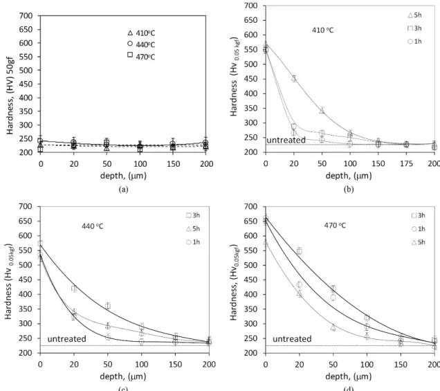
Figure 4a shows the hardness proile for the steel heated under the same conditions of plasma nitriding, but without plasma nitrogen. As can see, any signiicantly change in hardness is observed from the surface towards the core. Figure 4b-d shows the hardness proiles of the nitrided layers produced under the different conditions of temperature and time. For all nitrided layers, the maximum hardness was found at the material surface, decreasing gradually toward the core. Therefore, the veriied hardening is probably associated with the formation of nitrides or/and nitrogen in solid solution.
As shown in Figure 4b, for a temperature of 410 °C, increasing the nitriding time led to an increase in the hardness to 550-570 HV range. The nitriding depths increased with the nitriding time and reached values of approximately 20 μm after 1h, 80μm after 3h and 150μm after 5h.Further increases in the nitriding temperature led to a slight increase in the depths of diffusion zone. This effect is most likely associated with the early formation of a compound layer consisting of different types of nitrides, which make dificult for atomic nitrogen to diffuse towards the material core due to a low diffusion coeficient through these phases when compared to the ferrite matrix18.
Figure 4c shows that using temperatures of 440 °C enabled the production of a surface with hardness in the same range of that obtained using temperatures of 410 °C. The depth of nitrided layer for the 440 °C/3 h nitrided sample is approximately the same than the 410 °C/5h nitrided sample. It is also observed that the 5h nitrided sample appears to have undergone a softening process, when comparing its hardness proile with that of the 3h nitrided sample.
Figure 4d shows that the 470 °C nitrided samples followed the behavior found for the 440 °C nitrided samples, as the samples plasma nitrided for longer times also experienced a process of softening; the hardness proile of the 5 h nitrided sample is comparable with that of the 3h nitrided sample. At 470 °C, nitrided layers with surface hardness of approximately 650 HV could be achieved after either 1h or 3h of treatment; further increases in the nitriding time, however, led to the hardness fall to approximately 570 HV.
The softening on the top of the nitrided layers obtained at higher temperature and longer time is most likely due to: (i) the depletion of carbon (decarburizing process) that moves from the pearlite towards the material core19,20, as mentioned in the Section 3.1 or (ii) the transformation of the ε nitride into γ’ nitride21.A high surface hardness, therefore, can be achieved when a continuous layer, consisted predominantly of ε nitride, is formed on the material surface. The use of lower temperatures and shorter nitriding times is imperious when such layers are desirable.
Figure 2. Typical microstructure of the X-70 API steel.
3.3. Morphology
According to Blawert et al.18, the nitriding temperature is a variable that has a strong effect on the morphology and type of nitride which can be formed on the surface of plain carbon steels. Depending on the chosen parameters, two distinct layers are possible to form: the outer layer, referred to as compound layer; and, beneath it, the diffusion zone, in which the nitrogen atoms may be in solid solution and/or forming nitrides. The compound layer may not exist or be composed of nitrides (such as γ’-Fe4N and/or ε-Fe2-3N) depending on the nitriding conditions. For microalloyed steels, Lesage et al.15 veriied that both ε and γ’ seem to form preferentially when using high temperatures of treatment.
Figure 5 shows the cross-sectional microstructures of API 5L X-70 samples after plasma nitriding performed at 410, 440 and 470 °C. In all nitrided samples, it can be seen that the outer part appears not to be attacked by the etching reagent.As a result, a bright layer, referred to as compound layer15,18 was revealed This layer is thin, homogeneous and
continuous, covering the entire material surface. It can be concluded that all the studied conditions promoted the formation of the compound layer.It can be concluded that all the studied conditions promoted the formation of the compound layer.
For the 410 °C plasma nitrided samples, no precipitation of any nitride was detected in the diffusion zone. As suggested by the XRD analysis, the compound layer for these samples is characterized by the presence of γ’-Fe4N and ε-Fe2-3N phases. The relative intensity of the peaks of γ’ phase increased with the nitriding time, meaning that the volumetric fraction of the mentioned phase probably increased. Similarly, Lesage et al.15 veriied that longer nitriding times promoted the formation of a diffusion zone containing inely dispersed ε nitrides, as much as a compound layer comprised mostly of γ’ phase.
For samples nitrided for 1h/440 °C, some needles were produced bellow the compound layer, at the diffusion zoneand for the 5h/440°Cnitrided sample, these large needle-like nitrides still exist on the diffusion zone, growing much deeper
Figure 4. Hardness proiles of the API 5L X-70 pipe steel samples: (a) only heated and not plasma nitrided; (b, c and d) after plasma nitriding using 10% H2 + 90% N2, low rate of 400 cm
in comparison to that of the 1h or 3h/440 °C nitrided sample. The large needles (mostly 5 to 30 μm in length) possibly are comprised by γ’ nitride, as the XRD analysis detected only its presence. The γ’ nitride with a needle-like morphology was also observed by Lesage et al.15 after plasma nitriding anAPI 5L X-65 steel. According to these researchers, suitable conditions for the formation of a needle-like morphology were not well understood.
The formation of needles is favored whena nitriding temperature of 440 ºC was used, as can be conirmed in Figure 5. Blawert et al.18 reported similar results in ferritic steels submitted to plasma immersion ion implantation (PI3) process. These researchers also showed that the use of longer time of nitriding led to an increase in both the thickness of the compound layer and amount of needle-like nitrides, which may be dispersed at the diffusion zone. The presence of nitrides, as well their morphology, is strongly dependent on the processing temperature, amount of nitrogen dissolved on surface, and the steel composition. Although
both nitrides are equilibrium phases, information available on the FeN phase diagram is not always appropriate to predict the possible nitrides to be form on microalloyed steels, due to the presence of alloying elements which are strong nitride-forming elements. Alves et al.22, studying an AISI 1010 plain steel plasma nitrided at different temperatures, showed that low nitrogen concentrations were sufice for the formation of the γ’-Fe4N cubic nitride, whereas a high nitrogen surface concentrations promoted the formation of ε-Fe2-3N hexagonal nitride.
The needle-like nitrides grew at the diffusion zone, from the compound layer (surface) into the core. They are not visible at all on diffusion zone of thesamples plasma nitrided at 410 °C /5h or 470 °C/5h, suggesting that the increase in the nitriding time promoted a dissolution process of the needle-like nitrides, despite increasing the depth of diffusion zone. The XRD analysis showed that the compound layer may be consisted mostly ofγ’ nitride.
3.4. Wear resistance
Table 1 shows the wear coeficient for the samples plasma nitrided using different conditions of temperature and time. The treatment performed at 440 °C and 1h was the most beneicial because the highest wear resistance was possible to be reached. Using such condition, the nitrided layer is characterized by a diffusion zone with a relatively thin thickness, about 40 μm according to Figure 3b, containing much larger nitride precipitates. The XRD results, shown in Figure 2, suggest that the compound layer and the needle-like nitrides are constituted of ε and γ’phases, respectively. As shown in Table 1, for the 440 °C nitrided samples, the increase of the nitriding time led to a decrease in the wear resistance, despite the increasing in the thicknesses of diffusion zone and compound layer.
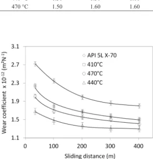
Figure 6 shows the wear coeficient as a function of the sliding distance for the samples plasma nitrided at 1h and different temperatures.
Both the untreated and nitrided samples, the wear coeficients decreased with the sliding distance and gradually
approached the steady state that occurs after approximately 400 m of sliding. The wear coeficient for the untreated steel decreased with the sliding distance from a maximum of 2.70×10⁻¹² m2/N at 20 m to 1.83×10⁻¹² m2/N at 300 m.
The “running-in” step23 for all samples was surpassed after about 300 m of sliding. At both short and long sliding distances, the wear coeficient of the untreated sample is ever higher than those of the nitrided samples.
The wear coeficients for nitrided samples are also seen to reduce with increasing sliding distance from the beginning of the test. For example, the wear coeficient for the 440 °C nitrided sample was reduced from 1.65 × 10⁻¹² m2/N at 20 m to 1.30 × 10⁻¹² m2/N at 300 m. The wear resistance of the nitrided samples increased when the temperature is increased from 410 °C to 440 °C, and decreased with additional increases.
The results presented here demonstrate that the control of temperature and time for nitriding a microalloyed steel is paramount. The presence of needle-like nitrides is good for wear resistance and a thicker diffusion zone is not always better for wear resistance. Therefore, plasma nitriding can effectively improve the sliding wear resistance of API 5L X-70 steel, as an increase in the wear resistance of the material was observed for all of the studied conditions and the best wear resistance was presented by the 440 °C/1h nitrided sample.
4. Conclusion
A signiicant improvement in the sliding wear resistance of API 5L X-70 pipe steel can be achieved when the material is plasma nitrided at relatively shorter times and lower temperatures.
The wear coeficients for the plasma nitrided steel under different conditions are lower than that of the untreated steel.
The hardness proiles of the nitrided layer are characterized by a surface hardness in the range of 550-650 HV.
The use of temperature of 440 °C and shorter nitriding time allows obtaining a compound layer, consisting predominantly of ε-Fe2-3N nitride, and a diffusion zone comprising of large needle-like γ’-Fe4N nitride, which offered the maximum wear resistance to the material.
The ε-Fe2-3N nitride by which the compound layer may be consisted is replaced for theγ’-Fe4N nitride when longer nitriding times are used, making worse the wear resistance of the steel.
The use of higher temperature promotes the dissolution of the γ’-Fe4N needle-like nitride on the diffusion zone, decreasing the wear resistance of the steel.
Acknowledgements
The authors are gratefully acknowledges the FINEP, CNPq and FAPES (Brazilian Research Funding Agencies) for inancial support.
Table 1. Wear coeficient of the API 5L X-70 steel plasma nitrided under different temperature and time.
Temperature Wear coeficient x 10
12(m2.N–1)
1 h 3 h 5 h
410 °C 1.55 1.50 1.50
440 °C 1.30 1.50 1.60
470 °C 1.50 1.60 1.60
Figure 6. Micro-abrasive wear coeficient as a function of sliding distance for API 5L X-70 pipe steel plasma nitrided for 1 h at different nitriding temperatures.
References
1. American Petroleum Institute - API. ANSI/API Speciication 5L, Speciication for Line Pipe. ISO 3183:2007 (Modiied): petroleum and natural gas industries: steel pipe for pipeline transportation systems. 44th ed. Washington; 2008.
2 . Shanmugam S, Ramisetti NK, Misra RDK, Hartmann J and Jansto SG. Microstructure and high strength-toughness combination of a new 700 MPa Nb-microalloyed
pipeline steel. Materials Science and Engineering
3. Lourenço NJ, Jorge AM Jr, Rollo JMA and Balancin O. Plastic behavior of medium carbon vanadium microalloyed steel at temperatures near γ←→α transformation. Materials Research. 2001; 4(3):149-156. http://dx.doi.org/10.1590/ S1516-14392001000300002.
4. Fernandéz AI, Uranga P, López B and Rodriguez-Ibabe JM. Dynamic recrystallization behavior covering a wide austenite grain size range in Nb and Nb–Ti microalloyed steels. Materials Science and Engineering A. 2003; 361(1-2):367-376. http:// dx.doi.org/10.1016/S0921-5093(03)00562-8.
5. Andrade H, Akben MG and Jonas JJ. Effect of molybdenum, niobium, and vanadium on static recovery and recrystallization and on solute strengthening in microalloyed steels. Metallurgical Transaction A. 1983; 14(10):1967-1977. http://dx.doi.org/10.1007/ BF02662364.
6. Ribeiro KJB, Ataide ARP, Alves C and Almeida EO. Novo método de revestir superfície interna de tubos transportadores de petróleo e derivados.In: XVI Congresso Brasileiro de Engenharia e Ciência dos Materiais, 2004. Porto Alegre: CBECIMAT; 2004. p. 1-11.
7. Wei R, Rincon C, Booker TL and Arps JH. Magnetic field enhanced plasma (MFEP) deposition of inner surfaces of tubes. Surface and Coatings Technology. 2004; 188-189:691-696. http://dx.doi.org/10.1016/j.surfcoat.2004.07.077.
8. Mongis J, Peyre JP and Tournier C. Nitriding of microalloyed steels. Heat Treatment of Metals. 1984; 11(3):71-75.
9. Mahboubi F, Samandi M, Dunne D, Bloyce A and Bell T. Plasma Nitriding of Microalloyed Steel. Surface and Coatings Technology. 1995; 71(2):135-141. http://dx.doi.org/10.1016/0257-8972(94)01012-8.
10. Kuppusami P, Sundararaman D and Raghunathan VS. Comparative study of plasma nitriding behaviour of a type 316 stainless steel and a microalloyed steel. Surface Engineering. 1993; 9(2):137-141. http://dx.doi.org/10.1179/sur.1993.9.2.137. 11. Sousa RRM, Moura YJL, Sousa PAO, Medeiros Neto JQ,
Costa THC and Alves Junior C. Nitriding of AISI 1020 steel: comparison between conventional nitriding and nitriding with cathodic cage. Materials Research. 2014; 17(3):708-713. http:// dx.doi.org/10.1590/S1516-14392014005000027.
12. Casteletti LC, Riofano RM and Nascente PAP. Influence of silicon content on ion nitriding of ultrahigh strength steels. Materials Science and Technology. 2004; 20(9):1171-1178. http://dx.doi.org/10.1179/026708304225021954.
13. Fanchin F, Rodrigues JA and Casteletti LC. Nitretação por plasma pulsado de aço do tipo SAE 1011: caracterização da camada nitretada. Revista Brasileira de Aplicações de Vácuo. 2000; 19(2):16-23.
14. Ashrafizadeh F. Influence of plasma and gas nitriding on fatigue resistance of plain carbon (Ck45) steel. Surface and Coatings Technology. 2003; 174:1196-1200. http://dx.doi.org/10.1016/ S0257-8972(03)00460-2.
15. Lesage L, Chicot D, Bartier O, Zampronio MA and de Miranda PEV. Influence of hydrogen contamination on the tensile behavior of a plasma ion nitrided steel. Materials Science and Engineering A. 2000; 282(1):203-212. http://dx.doi.org/10.1016/ S0921-5093(99)00753-4.
16. Cesconetto MCRL. Inluência da nitretação a plasma pulsado na resistência ao desgaste microabrasivo do aço API 5L X-70. [Dissertação]. Vitória: IFES; 2014.
17. Petersen DR, Link RE, Rutherford KL and Hutchings IM. Theory and application of a micro-scale abrasive wear test. Journal of Testing and Evaluation. 1997; 25(2):250-260. http:// dx.doi.org/10.1520/JTE11487J.
18. Blawert C, Mordike BL, Rensch U and Oettel H. The effect of HV in the nitriding of ferritic steels by plasma immersion ion implantation. Surface and Coatings Technology. 2001; 142-144:376-383. http://dx.doi.org/10.1016/S0257-8972(01)01314-7. 19. Lightfoot BJ and Jack DH. Kinetics of nitriding with and
without white-layer formation. In: Proceedings of The 73’ Heat Treatment; 1973. London: Metals Society; 1973. p. 12-13.
20. Abd El-Rahman AM, El-Hossary FM, Fitz T, Negm NZ, Prokert F, Pham MT, et al. Effect of N2 to C2H2 ratio on r.f. plasma surface treatment of austenitic stainless steel. Surface and Coatings Technology. 2004; 183(2–3):268-274. http://dx.doi. org/10.1016/j.surfcoat.2003.09.057.
21. Somers MAJ and Mittemeijer EJ. Layer-growth kinetics on gaseous nitriding of pure iron: evaluation of diffusion coefficients for nitrogen in iron nitrides. Metallurgical and Materials Transaction A. 1995; 26(1):57-74. http://dx.doi.org/10.1007/ BF02669794.
22. Alves C Jr, Lima JA, Hajek V, Cunha JBM and Santos CA. Effect of cooling rate on properties of plasma nitrided AISI 1010. Surface and Coatings Technology. 2007; 201(16-17):7566-7573. http://dx.doi.org/10.1016/j.surfcoat.2007.02.036.