This is an Open Access article distributed under the terms of the Creative Commons Attribution Non-Commercial License Received 07 Oct., 2016
Accepted 08 May, 2017
E-mails [email protected] (IGF), [email protected] (BVA), [email protected] (JJGD), [email protected] (CECG), [email protected] (MAGA), [email protected] (JPV)
Abstract: The effect of torch weaving on the microstructure, tensile strength, impact resistance and fracturing in robotic welded joints using varing welding speeds, voltages and currents was evaluated through fractography using scanning electron microscopy, tension, impact and micro-hardness tests and optic microscopy. Results indicated that linear, sinusoidal and circular weavings favored an increase of the width of the HAZ as well as a slight increase in yield resistance accompanied by hardening in comparison with a triangular weave. The latter favored larger impact energy in the HAZ with less width, containing coarse-grained ferrite due to lower tensile strength and Vickers hardness. A circular weave generated the highest level of hardening and the lowest energy absorbed in the HAZ as a consequence of an increase in yield strength related to the fine needles of acicular ferrite. A linear weave favored the greatest width of the HAZ compared with other weld weavings due to heat accumulation along the fusion line of the welded joint. Hardening and loss of toughness were evaluated through fractographic analysis showing mixed fractures mainly composed of brittle fracturing made by transgranular cleavages with facets containing well defined river patterns.
Key-words: HAZ; Cleavage fracture; Robotic welding; Torch weaving; ASTM A36 steel.
Efeito do Movimento da Tocha na Microestrutura, Resistência à Tração
e ao Impacto, e Fratura da ZAC e Cordão de Solda por Processo GMAW
Robotizado em Aço ASTM A36
Resumo: O efeito do movimento da tocha sobre a microestrutura, resistência à tração e impacto e fratura em juntas soldadas por processo robotizado, variando velocidade, voltagem e corrente de soldagem foi avaliado através de fratografia, usando microscopia eletrônica de varredura, provas de tração e impacto e testes de microdureza e microscopia óptica. Os resultados indicaram que os movimentos lineares, senoidais e circulares favorecem um aumento da largura da ZAC, assim como, um ligeiro aumento do limite elástico acompanhado de endurecimento em comparação com o movimento triangular. A energia de impacto é mais favorecida na ZAC com menor largura, contendo grãos grosseiros de ferrita devido à menor resistência à tração e dureza Vickers. Um movimento circular produziu o nível mais elevado de endurecimento e a menor energia absorvida na ZAC como consequência de um aumento na limite elástico relacionado com as agulhas finas de ferrita acicular. Um movimento linear favoreceu maior largura da ZAC em comparação com outros movimentos da tocha, devido à acumulação de calor ao longo da linha de fusão da junta soldada. Endurecimento e perda de tenacidade foram avaliados através de análise fratográfica mostrando fraturas mistas compostas principalmente de fratura frágil por clivagem transgranular com facetas contendo marcas de rio bem definidas.
Efect of Torch Weaving on the Microstructure, Tensile and Impact Resistances,
and Fracture of the HAZ and Weld Bead by Robotic GMAW Process on ASTM A36
Steel
Isidro Guzman-Flores1, Benjamin Vargas-Arista2, Juan Jose Gasca-Dominguez3, Celso Eduardo Cruz-Gonzalez4,
Marco Antonio González-Albarrán5, Joaquin del Prado-Villasana3
1 Insituto Tecnológico de Aguascalientes, Aguascalientes, México.
2 Insituto Tecnológico de Tlalnepantla, División de Estudios de Posgrado e Invesigación, Tlalnepantla de Baz, Estado de
México, México.
3 Manufacturera de cigueñales de México – MACIMEX, Centro de Invesigación, Innovación y Desarrollo Avanzado, Tenango del
Valle, Estado de México, México.
4 Gerencia de Sistemas Dinámicos y de Transferencia, Centro de Ingeniería y Desarrollo Industrial – CIDESI, Queretaro, México.
1. Introduction
Pulsed arc GMAW robotic welding with torch weaving is a process found in the renewable energy industry. The main goal is to increase weldability and quality of steel used in multi-step welded joints present in the
components common to this sector and also in metallic structures [1]. In particular, ASTM A36 structural carbon
steel could be an option for manufacturing structural components that require the new robotic welding technology. Furthermore, torch weaving has been broadly used to improve welding quality by solving the problem of lack of
fusion in lateral walls and generating larger welding beads, thus improving efficiency [2].
Fields of study belonging to the metallurgy of robotic welding are the formation of the conventional HAZ composed by recrystallized microstructures, as well as the reheated HAZ between weld passes, formed by different morphologies of ferrite from acicular passing through allotriomorphic, idiomorphic and coarse grains, which
were linked to hardening and loss of toughness [3], presence of fragile martensite located at the fusion line and
hot cracking susceptibility in the weld bead in structural carbon steel welded joints. All of these issues limit the
metallurgy and quality of the aforementioned joints [4].
There has been some work on robotic welding focused on welding metallurgy, functionality and technical
capabilities of adequate performance techniques [2,4,5]. This research is related to Chen et. al, 2014 and reported
on the effect of the frequency and amplitude of weaving on welding temperature distribution under different weaving values. Peak and mean temperatures at the center of the weld bead dropped due to the increase in both
parameters of weaving. Nevertheless, frequency has a lesser effect on mean temperatures [2]. In the study of the
effect of different wires with weaving used in the GMAW robotic welding process on the quality and penetration of joint fillets between stainless steel AISI 304L and structural steel S355MC porosity was detected in the roots of the welds in samples welded with weaving due to the low efficiency in gas protection. Formation of a narrow martensitic band around the fusion line on the ferritic side of the welded joint was detected on the majority of samples obtained using weaving, resulting in hardening favored by quick solidification. Torch weaving lowered
penetration on the structural steel side due to rapid heat dissipation and higher heat conductivity [4]. Another
study reported the effect of three significant variables, namely welding current, arc voltage and welding speed over the penetration of 6842 steel welded using a GMAW robotic process. The result was that a higher current increased the depth of penetration of the weld metal. The greatest penetration was observed at an intermediate
speed of 60 cm/min [6].
However, the critical problem is that few publications exist containing fractography, mechanical and microstructural characterizations of the HAZ and weld metal in joints welded by a robot using torch weaving on carbon steel such as ASTM A36 making it difficult to have more complete knowledgement regarding welding metallurgy for both kinds of microstructural zones in order to produce further understanding of the relationships among causes and effects of the fracture behavior on service life.
The main objective of this investigation is a comparative analysis of the microstructure, tensile strength, micro-hardness, toughness (measured as Charpy absorbed energy) and fractography of butt welded joints using a robot with four torch-weaving types for the aforementioned steel to contribute to the welding metallurgy and improve the quality of the robotic joints. The originality of this research is found, on one hand, in the fact that the HAZ is a detrimental microstructural hardened zone with low toughness where cold cracking is nucleated, affecting the lifespan of welded components, in this case, solar structures. Elsewhere, the HAZ should be minimized, this includes its width in the joint by using correct welding parameters optimized to avoid cracking once robotic
welding cycle is over [7].
2. Methodology 2.1. Materials
Samples of butt welded joint were taken using ASTM A36 carbon steel plates that were 250x250x9.5 mm in length, width and thickness, respectively. The weld position of A36 plates for the groove welded joints was the test position 1G, i.e., flat welds. The plates were longitudinally welded using a GMAW-MIG technique under welding procedure specification (WPS). Preparation included a 60º bezel in the area to be welded. The electrode used was
was 15 L/min, all according to standards DIN EN 1011-2 [7] and UNE-EN ISO 15609-1 [8]. The MIG process used
short circuit metal transference by means of a pulsed arc with four different welding parameters using a Comau stationary robot with manual control, a C5G arm with six motion axes, a workstation with two work tables and a Fronius power supply model Transpuls 4000.
The chemical composition of the solid welding wire ER70S6 and base steel ASTM A36 in original conditions
as per AWS A5.18 [9] and DIN EN 10025-2 [10], respectively, is listed in Table 1. Values of equivalent carbon (C
eq)
were calculated using Equation 1 found in DIN EN 1011-2 [7] and were in agreement with DIN EN 10025-2 [10].
The chemical composition was obtained using optical emission spectrometry from Spectrolab. Carbon and sulfur contents were obtained using the direct combustion method and infrared detection.
(
)
(
)
/ 6 / 5 / 15
eq
C = C + Mn + Cr + Mo + V + Ni + Cu (1)
Table 1. Chemical composition of ER70S6 electrode and ASTM A36 steel.
Material
Element (Wt. %)
C Mn Si Nb P S Ceq
ER70S6 0.10 1.15 0.41 0.010 0.002 0.008 0.310
ASTM A36 0.055 0.943 0.015 ---- 0.009 0.004 0.212
Table 2. Micro-wire ER70S6 and base metal ASTM A36 mechanical properties.
Material Vickers hardness
HVN, 500 gf
YS 0.2% (MPa) UTS (MPa) Elongation (%)
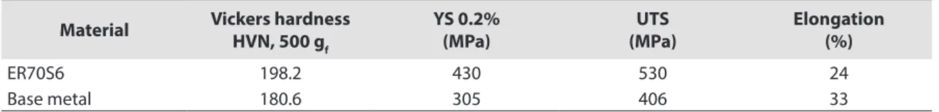
ER70S6 198.2 430 530 24
Base metal 180.6 305 406 33
Electrode and base metal mechanical properties are presented in Table 2. They comply with the aforementioned standards. We can see that the weld metal showed greater mechanical strength than the base metal, which complies with the basics in the design of welded joints.
Based on previous experimentation, the design of factorial experiments using Minitab 2015 software [11] for
the GMAW robotic welding process was based on four critical parameters: welding speed (Ws) with two values,
power (P, energy to weld depending of average welding current and mean arc voltage) taking two values into
account, arc length (Al, longitude among wire and work piece) with two values and four types of torch weaving
(linear, triangular, sinusoidal and circular) including the values of amplitude and frequency, as shown in Table 3. This resulted in seven experimental trials grouped in two welding conditions, A and B, for butt welded joints.
Aditionally, the net heat input values were calculated by Equations 2 and 3 [12] for both welding conditions, which
are included in Table 3.
net arc
Q = ηQ (2)
where: Qnet = net heat input (kJ/mm); Ƞ = heat transfer eiciency, 0.85 for GMAW process.
(
/)
60(
/)
arc
Q = E I S = arc energy kJ mm (3)
2.2. Mechanicals testing
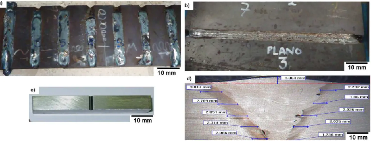
Samples of welded joints were machined according to testing specifications for Charpy impact, tension,
micro-hardness and microscopy, see Figure 1. In order to evaluate Vickers hardness at the butt welded joint, we
made use of transversal probes that were 10×40 mm in width and length, respectively. To characterize tensile strength of the welded joints we used reduced flat transversal probes that were 25 mm of calibrated length, 6 mm in width, 14 mm in thickness and 120 mm in total length, having the joint at their center. To determine the impact energy of the HAZ, reduced type A probes were machined having a rectangular transversal section, transversal orientation, 55 mm in length, 10 mm in width and thickness, and a 45º V-notch located at the HAZ of the welded joint. The latter was made using a Blacks Charpy broaching machine.
Table 3. Robotic welding parameters for this study.
Specimen/ condition
Welding current (A)
Arc voltage
(V)
Welding speed (cm/min)
Arc length
(%) Power (%)
Net heat input Qnet
(kJ/mm)
Torch weaving (Frequency (Hz)/ Amplitude (mm))
1A 201.2 26.8 38.5 −5 63 0.714 Triangular (1.28/ 3)
2A 201.2 26.8 38.5 −5 63 0.714 Sinusoidal (1.28/ 3)
3A 201.2 26.8 38.5 −5 63 0.714 Lineal (1.28/ 3)
4A 201.2 26.8 38.5 −5 63 0.714 Circular (1.28/ 3)
5B 159.2 23.2 31.5 +5 43 0.599 Lineal (1.05/ 3)
6B 159.2 23.2 31.5 +5 43 0.599 Triangular (1.05/ 3)
7B 159.2 23.2 31.5 +5 43 0.599 Sinusoidal (1.05/ 3)
Figure 1. (a) Butt welded joints for impact testing; (b) GMAW robotic joints for tension testing; (c) Charpy specimen; and (d) sample for Vickers hardness and microstructural evaluation.
Vickers hardness was evaluated using micro-hardness Durascan Emco with Ecos Workflow software. The test
applied a load of 4.9 N and took 10 readings for every microstructural zone as per ASTM E384M [13]. An uni-axial
tension test was done on a Shimadzu universal machine with a 1,000 kN load cell in displacement mode and
a deformation rate of 15 mm/min was used as set in ASTM E8M [14]. Impact testing was done using a Charpy
Satec pendulum at −20 °C. The test was repeated three times using probes with a V notch on the HAZ for both
welding conditions as shown in ASTM E23M guidelines [15]. The weld beads in the joints exhibited defects such as
2.3. Microstructural characterization
For microstructural characterization we used probes cut from the welded joints. The probe’s dimensions were 40 mm in length and 10 mm in width. They were rough and then polished with alumina in water and subsequently were etched with Nital 2% solution to reveal microstructural characteristics of the zones under study using an Nikon optic microscope with inverted plate and digital camera connected to a computer having NIS-element D3.2 software.
2.4. Fractography
Finally, fractographic analysis along the HAZ of the fractured probes due to the impact testing was done using a CARL ZEISS-Gemini Supra 55 VP field emission scanning electron microscope brand working at 10 kV and a secondary eléctron signal.
3. Results and Discussion
The change in torch weaving (sinusoidal, linear and circular), welding speed, power and arc length influenced the welding metallurgy as well as the dissipation and accumulation of heat and solidification (cooling) within welded
joint, affecting the microstructural zones which showed hard phases resulting in Vickers hardening [4], an increase
in HAZ width, an increase in yielding strength, reduction of impact energy and degradation of quality. However, the triangular torch weaving favored the best metallurgical quality of the butt welded joint.
3.1. Macrostructural analysis
The quality of a welded joint is a function of the lowest mean HAZ width, a bezel root with no weld excess,
uniformity in the weld face, minimum reinforcement of the weld bead and the absence of defects such as porosity [4],
lack of fusion and incomplete penetration. For welding condition A (201 A, 27 V, Ws=38.5 cm/min) we observed
that quality of the welded joint was lowest in the circular weld, followed by the sinusoidal and linear in comparison with the triangular weave. The latter generated a narrower average HAZ width, a bezel root without weld excess,
a uniform weld face and minimal reinforcement of the weld bead, resulting in better quality [2].
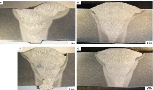
We found that the HAZ width increased for three types of weaving when compared to triangular weaving.
The linear weave generated the largest HAZ width (1.84 mm) showing a 30% increase (Figure 2a), followed by
sinusoidal with 24%, i.e., HAZ width of 1.76 mm (Figure 2b) and circular with 14% generating a HAZ width of
1.62 mm (Figure 2c) in comparison to the minimum value (1.42 mm) of triangular weaving (Figure 2d) where the
heat was quickly dissipated due to accelerated cooling.
The behavior of the largest HAZ width generated by lineal weaving was related to heat accumulation under the arc in a limited linear zone, which meant that cooling was delayed, giving rise to a greater thermal affectation at the point of fusion. This heat could be calculated using numerical temperature distribution in horizontal position
robotic welding during the thermal cycle [16]. Furthermore, this welded joint presented weld excess at the root
and a discontinuous weld face skewed to one side of the joint, see Figure 2a.
Considering the reinforcement in these welded joints we found that triangular weaving generated the lesser (1.749 mm), followed by circular (2 mm), linear (2.308 mm) and sinousoidal weaving (2.712 mm) which presented the greatest reinforcement. Lastly, the joint made with circular weave showed the largest amount of weld excess at the root, lack of fusion at the upper part of the joint, pore with a mean diameter of 0.613 mm located at the
fusion line in the lower part of the joint and obvious plate misalignment which can be observed in Figure 2c.
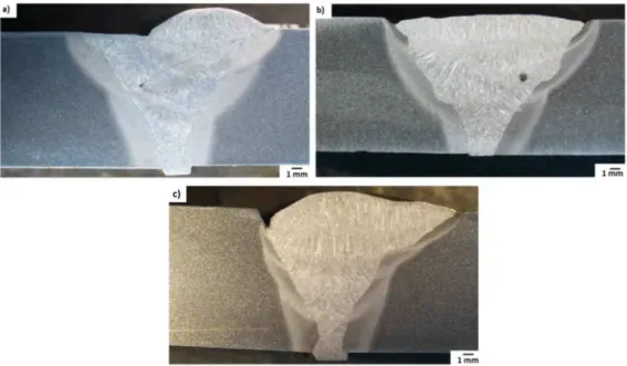
Under welding condition B (159 A, 23 V, Ws = 31.5 cm/min) a notorious increase in the mean HAZ width reaching
77% was found to be generated by linear weaving with a HAZ width of 2.05 mm (Figure 3a). Sinusoidal weaving
followed with 52%. i.e., 1.76 mm of HAZ width (Figure 3b) while triangular weaving had the lowest HAZ width
(1.16 mm) favored by a 21% reduction in welding current, see Figure 3c.
In linear weaving, weld excess was found at the root of the joint, 0.182 mm pore diameter at the fusion line between welding beads close to the base metal and the weld face height measured at 2.072 mm not centered at
one side of the joint, see Figure 3a. For sinusoidal weaving, the mean pore diameter measured 0.545 mm at the
fusion line between welding beads near the base metal, there was a lack of fusion on both sides of the weld joint
and the weld face presented minimum reinforcement of 0.278 mm (Figure 3b). Triangular weaving generated an
evident lack of fusion next to the joint, as well as excess weld at the root of the joint and a bead reinforcement
height of 0.752 mm (Figure 3c).
Figure 3. Macrographies of butt welded joints under welding condition B (159 A, 23 V, Ws = 31.5 cm/min) using GMAW robotic welding and different weld weaving: (a) linear; (b) sinusoidal; and (c) triangular.
3.2. Microstructural evolution
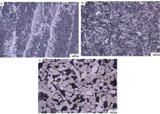
After microstructural observation using optic microscopy of specimens under welding condition A, we found that microstructures generated in the HAZ and welding beads, after using the four types of weld weave, showed morphologic differences in the microstructural phases in terms of types, sizes and quantities. Circular weaving produced weld metal formed by column-like fine ferritic grains containing a larger amount of Widmastatten ferrite
sideplates which are separated by fine acicular ferrite in a greater quantity (Figure 4a). The HAZ in the fusion line
was formed by an acicular ferritic matrix in the form of fine needles, see Figure 4b [17]. Furthermore, ASTM A36
steel showed a microstructure composed of a matrix of equiaxial ferritic mixed grain sizes and the presence of
pearlite colonies with different sizes and also non-metallic inclusions (grey points) across the grains, see Figure 4c.
Figure 4. Micrographies obtained through optic microscopy from the butt welded joints under condition A with circular weaving: (a) fine Widmasttaten ferrite in weld; (b) fine acicular ferrite needles in HAZ; and (c) pearlite in base metal.
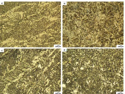
Linear weaving generated welds with column-like medium grains containing a smaller quantity of Widmastatten
ferrite, separated by fine acicular ferrite (Figure 5a), as well as a HAZ where medium acicular ferrite in the shape of
needles was observed (Figure 5b) [17]. On the other hand, sinusoidal weaving favored welding metal with contents
having a smaller amount of fine acicular ferrite among enlarged medium ferritic grains (Figure 5c), while the HAZ
was mainly formed by fine acicular ferrite with lower contents of idiomorphic ferrite (Figure 5d).
Finally, triangular weaving favored weld metal with medium column-like ferritic grains separated by a smaller
amount of acicular ferrite, see Figure 6a. The HAZ showed a larger amount of coarse-grained ferrite in the presence of acicular fine ferrite (Figure 6b).
Based on the observed microstructural results for welding condition A in the weld metal for linear, sinusoidal and circular weavings we found some grain refinement of column-like ferrite, acicular ferrite and lateral sideplates
of Widsmastatten ferrite [17]. This was, however, more notorious in circular weave. A Triangular weave favored
medium elongated grains. For the HAZ, the three torch weaving types we just mentioned generated fine acicular
Figure 5. Micrographies obtained through optic microscopy from the butt welded joints under condition A with linear weaving: (a) medium columnar ferrite in weld; (b) medium needles of acicular ferrite in HAZ, sinusoidal weave: (c) medium acicular ferrite in weld; and (d) idiomorphic ferrite in HAZ.
Figure 6. Micrographies obtained through optic microscopy from the butt welded joints under condition A with triangular weaving: (a) medium column-like grains in weld; (b) coarse grain ferrite in HAZ.
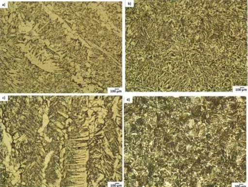
For welding condition B the following microstructure characteristics were observed. A linear weave favored
weld metal with medium columnar grains separated by fine acicular ferrite (Figure 7a) while the HAZ exhibited a
matrix of medium acicular ferrite-like needles (Figure 7b). A triangular weave generated weld metal formed by a
larger amount of lateral plates of Widmastatten ferrite along the medium columnar grains separated by acicular
ferrite (Figure 7c) and the HAZ showed the presence of coarse grain ferrite contained in a fine acicular ferrite
matrix (Figure 7d).
Finally, sinusoidal weaving generated welds with a larger quantity of Widmastatten ferrite [17] growing
of linear weave, favoring the formation of Widmastatten ferrite present in weld metal in the cases of triangular
and sinusoidal weavings, and the formation of needle-type acicular ferrite in the HAZ [17] in the case of linear and
sinusoidal weaves.
In addition, comparing welding conditions A and B, we found that linear weave induced the greatest HAZ
width, affecting the weldability of the joint and favoring susceptibility to cracking [10]. Therefore, condition B is not
recommended for welding [4]. HAZ width and microstructural characteristics observed for the four torch weaving
types could influence the behavior of Vickers hardness, tensile strength and impact energy as described in the following sections.
Figure 7. Micrographies obtained through optic microscopy from the butt welded joints under condition B with linear weave: (a) medium column-like grains in weld, (b) acicular ferrite needles in HAZ, triangular weaving: (c) Widmastatten ferrite in weld, and (d) coarse grain ferrite in HAZ.
3.3. Vickers hardness
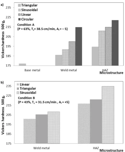
For welding condition A, the results of the micro-hardness test revealed that the three torch weaving
types (sinusoidal, linear and circular) modified the hardness in the HAZ and weld metal, favoring hardening [4] in
comparison to values from triangular weave, the former leading to the least hardness for both microstructural
zones (Figure 9a).
It was found that the HAZ reached a greater Vickers hardness than the weld metal for the four torch weaving types due to microstructural changes in the size and amount of acicular ferrite and coarse-grained ferrite linked to the heat, resulting in greater thermal affectation at the fusion line between welding beads and the base metal.
Circular weaving generated the largest increase in micro-hardness in the weld metal (16%) and the HAZ (14%), followed by linear weave with 11% for the HAZ and 8% in the weld and the sinusoidal weaving gave rise to 9% for the HAZ and 3% in the weld, all being compared to the hardness values generated in the weld metal and the HAZ with triangular weave, which was associated with the largest amount of fine needles of acicular ferrite in the HAZ and the formation of fine grains of column-like ferrite containing a larger amount of fine lateral plates of Widmastatten ferrite in the weld. Thus, triangular weaving generated a lower hardness in both microstructural zones
Results of micro-hardness testing for condition B indicated that sinusoidal weaves reached the highest level of hardness, followed by triangular and linear weavings (Figure 9b), which give a larger amount of fine Widmastatten plates in the welding metal and fine needles of acicular ferrite in the HAZ when compared to microstructural features generated by linear weaving with medium column-like ferritic grains in the weld metal and acicular ferrite in the shape of medium-sized needles in the HAZ.
Hardening [4] was evident when comparing different torch weaving types for cases A and B. Thus, condition
B is not adequate [4] if quality welded joints are to be obtained, since it favored microstructural hardening as
mentioned above. It also generated a larger HAZ width when a linear weave was used. Defects such as porosity [4],
lack of fusion and excess welding at the lower part of the joint were also generated. Hardening behavior was directly related to tensile strength, as described in the following section.
3.4. Mechanical strength
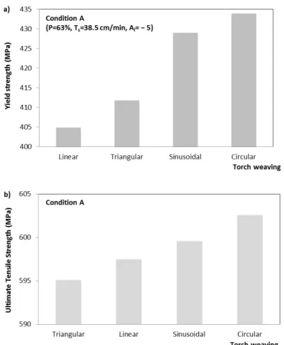
For welding condition A, it was found that the yield strength increased more when different weld weaving was used. The most notorious increase was found with circular weaving (6%) which was followed by sinusoidal (4%) and triangular weaves when compared to linear weaving, which showed lower resistance (Figure 10a). However, the ultimate tensile strength slightly increased when the torch weaving was changed (Figure 10b). Circular weave generated the highest strength, followed by sinusoidal and linear weaves in comparison to the triangular weaving that showed the least strength and micro-hardness. Thus, an evident effect of the welding parameters on the tensile strength was not found.
This mechanical behavior confirmed hardening [4] found in circular, sinusoidal and linear torch weavings.
This increase in yielding strength was related to hard microstructural phases such as fine lateral Widmastatten ferrite sideplates in weld metal and fine needles of acicular ferrite in the HAZ for circular weaves. Finally, there was not a significant reduction in elongation with respect to the four different weave types here analyzed, as can be observed in Table 4. Based on this we can say that weld weaving directly influenced yield strength causing changes permanent plastic deformation begins.
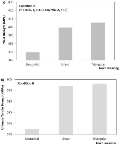
Tension test results for welding condition B indicated that triangular weave generated the largest increase
in yield strength (Figure 11a) and tensile strength (Figure 11b), followed by linear and sinusoidal weaves with
the least mechanical strength. The latter is attributed to the combination of welding parameters used. It was observed that yield strength increased more than tensile strength. At the same time there was no significant change in elongation for any of the welding weave types, and therefore the ductility of the butt welded joint was
not affected, see Table 4.
If we compare both welding cases, sinusoidal weaving generated a clear reduction in yield and ultimate tensile strengths of the welded joint. Linear and triangular weavings generated similar values in strengths. Thus, condition B did not favor a significant increase in mechanical strength. On the contrary, sinusoidal weave generated a notorious decrease when compared to its results under condition A. Finally, both welding conditions gave rise to similar elongation values for the three types of weaving, with no affectation in the joint’s ductility.
Table 4. Values of elongation for transversal welded joints at conditions A and B.
Specimen/ condition Torch weaving Elongation (%)
1A Triangular 20.7
2A Sinusoidal 20.5
3A Lineal 20.6
4A Circular 20.4
5B Lineal 20.7
6B Triangular 21.2
7B Sinusoidal 20.4
3.5. Impact energy
Impact energy values for the HAZ at −20 °C of four butt welded joints for welding condition A were collected,
see Figure 12a. We found that circular weaves reached the lowest Charpy energy followed by the sinusoidal,
triangular and linear torch weavings, which reached the highest value of energy absorbed. Circular weaving generated a 45% reduction of impact energy with respect to linear weave, which was linked to greater yield and tensile strengths and greater Vickers hardness. For triangular weaving more energy was absorbed (an increase of 43%) than that generated with a circular weave due to lower tensile strength and micro-hardness, as well as a narrower HAZ. Thus, triangular weave is recommended to obtain an adequate weldability in robotic welded joints.
For condition B, it was observed that the linear motion showed the least impact energy absorbed, followed
by sinusoidal and triangular weaving having the largest amount of energy, see Figure 12b. Thus, linear weaving
generated a reduction of 67% in Charpy fracture energy when compared to triangular weave.
Figure 12. (a) Charpy energy, and (b) Impact energy as a function of torch weaving in butt welded joints using a GMAW robotic welding process for welding conditions A and B, respectively.
Comparing both welding cases, we observed that condition B favored a 60% reduction in Charpy energy for linear weaving which is thought to be due to a greater Vickers hardness when compared to condition A. Therefore, welding condition B is not advised since it reduces impact energy for linear weave.
3.6. Charpy fractography
Reduction in Charpy energy, increase in yield strength, hardening [4] and the presence of hard phases like
acicular ferrite needles generated in the HAZ [10] were confirmed using fractographic analysis with a scanning
facets of different sizes containing river patterns, and zones of ductile fracture with morphology of transgranular microhollow morphology, the latter showing a significant change in quantity as a consequence of the change in torch weaving.
Circular weaving favored the presence of a smaller quantity of microhollows distributed in a network and
a larger amount of fragile fracture due to transgranular cleavage throughout the fractured surface (Figure 13a)
resulting in a lower value of impact energy, followed by sinusoidal weave (Figure 13b) for condition A, and linear
weaving for condition B (Figure 13c) with the least impact energy. These results were compared to triangular weave
of condition B which mainly generated a ductile fracture with transgranular microvoids (Figure 13d) absorbing
the largest amount of energy.
Figure 13. Fractographies of impact fractures in the HAZ for four types of torch weaving showing different amount of fragile fracture: (a) circular; (b) sinusoidal and (c) linear with cleavage facets; and (d) triangular with ductile fracture containing microhollows.
4. Conclusions
1. The four torch weaving types studied here affected the mechanical properties under tension and impact, as well as microstructural characteristics in the HAZ and weld metal of butt welded joints using a GMAW robotic welding process;
2. For welding condition A, the linear, sinusoidal and circular weavings favored an increase in HAZ width, as well as a moderate increase in yield strength together with a notorious higher hardening of the HAZ than that of weld beads when compared to triangular weave. The latter favored larger Charpy impact energy values in the HAZ with the smallest width due to a lower ultimate tensile strength and Vickers hardness. This behavior was attributed to the presence of coarse-grained ferrite when compared to the other torch weaving types. Therefore, the triangular weave was the best in terms of improved mechanical properties under tension and impact, lowest hardness of weld metal and HAZ, and generation of adequate microstructural characteristics; 3. For condition A, circular torch weaving generated the highest level of hardening and the lowest absorbed
zone of the HAZ. This metallurgical behavior was confirmed by a fractographic analysis, resulting in surfaces with mixed failure mainly composed by fragile fracture morphology due to transgranular cleavage with well-defined river-patterned cleavage facets;
4. Linear torch weaving favored the largest HAZ width containing acicular ferrite needles for both welding conditions A and B when compared to the other types of weavings. This was related to the heat accumulation along the fusion line of the butt welded joint. Circular, linear and sinusoidal torch weaving types are not recommended to robotic weld since they generated hardening, an increase in yield strength and more microstructural heterogeneity in the HAZ with hard acicular ferrite needle phases.
Acknowledgements
The authors wish to thank the experimental and financial supports received from the MACIMEX Tenango and COMECyT, respectively.
References
[1] Kumar BP. Effect of welding parameters of gas metal arc welding on weld bead geometry: a review. International Journal of Engineering Science and Technology. 2012;4(7):3446-3449. [2] Chen Y, He Y, Chen H, Zhang H, Chen S. Effect of weave frequency
and amplitude on temperature field in weaving welding process. International Journal of Advanced Manufacturing Technology. 2014;75(5):803-813. http://dx.doi.org/10.1007/s00170-014-6157-0. [3] González-Gutiérrez S, Vargas-Arista B, Solís J, García-Vázquez F.
Effect of wire feed rate on the microstructure and microhardness
of multilayer weldment by GMAW process on ASTM A633 steel. In: Proceedings of the 32th Congreso Internacional de Metalurgia y Materiales; 2010; Saltillo. Mexico: UNL; 2010. p. 1-11. [4] Tasalloti H, Kah P, Martikainen J. Effects of welding wire and
torch weaving on GMAW of S355MC and AISI 304L dissimilar welds. International Journal of Advanced Manufacturing Technology. 2014;71(1-4):197-205. http://dx.doi.org/10.1007/ s00170-013-5484-x.
[5] Lee D, Ku N, Kim T-W, Kim J, Lee K-Y, Son Y-S. Development and application of an intelligent welding robot system for shipbuilding. Robotics and Computer-integrated Manufacturing. 2011;27(2):377-388. http://dx.doi.org/10.1016/j.rcim.2010.08.006. [6] Karadeniz E, Ozsarac U, Yildiz C. The effect process parameters on penetration in gas metal arc welding processes. Materials & Design. 2007;28(2):649-656. http://dx.doi.org/10.1016/j. matdes.2005.07.014.
[7] Deutsches Institut fur Normung. DIN-EN 1011-2: recommendations for welding of metallic materials, part 2 arc welding of ferritic steels. Berlin: DIN; 2001. 9 p.
[8] Asociación Española de Normalización. UNE-EN ISO 15609-1: specification and qualification of welding procedures for metallic materials, Part 1 Arc welding. Spain: AENOR; 2004. p. 6-10.
[9] American Welding Society. AWS A5.18: Specification for carbon steel electrodes and rods for gas shielded arc welding. Miami: AWS; 2005. p. 2-6.
[10] Deutsches Institut fur Normung. DIN-EN 10025-2: hot rolled products of structural steels, part 2 technical delivery conditions for non-alloy structural steels. Berlin: DIN; 2004. p. 18-29. [11] Cruz C, Hiyane G, Mosquera-Artamonov JD, Salgado L JM.
Optimization of the GTAW process for Ti6Al4V plates. Soldagem & Inspeção. 2014;19(1):2-9. http://dx.doi.org/10.1590/S0104-92242014000100002.
[12] Atkins G, Thiessen D, Nissley N, Adonyi Y. Welding process effects in weldability testing of steels. Welding Journal. 2002;81(4):61-66.
[13] American Society for Testing and Materials. ASTM E384M:
standard test method for microindentacion hardness of
materials. West Conshohocken: ASTM; 2005. p. 1-8. [14] American Society for Testing and Materials. ASTM E8M: standard
test methods for tension testing of metallic materials. West Conshohocken: ASTM; 2008. p. 7-18.
[15] American Society for Testing and Materials. ASTM E23M: standard test methods for notched bar impact testing of metallic materials. West Conshohocken: ASTM; 2006. p. 2-8. [16] Kumar A, Debroy T. Heat transfer and fluid flow during
gas-metal-arc fillet welding for various joint configurations and welding positions. Metallurgical and Materials Transactions. A, Physical Metallurgy and Materials Science. 2007;38(3):506-519. http://dx.doi.org/10.1007/s11661-006-9083-4.