DOI: http://dx.doi.org/10.1590/1516-1439.211013
Materials Research. 2014; 17(6): 1485-1488 © 2014
*e-mail: [email protected]
1. Introduction
Manufacturing of ceramic-coated non-ferrous alloy components may, in principle, yield beneits over the use of more traditional materials such as ceramics, high-alloy steels and cast iron1,2. Certainly, light alloys can offer increased reliability at high loads along with the associated reduction in weight3. Correspondingly, shortcomings of ceramic coatings include poor performance under insufficient lubrication4, as, e.g. is the case with Ti nitride/carbide coatings5; due to the latter’s low wetability, the lubricant ilm is compromised leading to increased wear. This is owing to the very nature of the ceramic which, due to its high friction coeficient, mediates heating of the friction interface as a result of the micro-cutting effect, and chipping of ceramic particles which, in turn, accelerate abrasive wear4. Extensive surface inishing to a roughness lower than Ra 0.05 µm can alleviate this problem in part6. Alternative means of achieving increased wear protection, particularly in the case of Al, Mg and Ti-based alloys, involve the application of various nanoillers in the pores of the ceramic coating; popular such illers are e.g. luoropolymers7 and SiO2 particles applied via sol-gel technology8. Invariably, however, such coating augmentation limits applications to low temperatures. Gas-thermal dusting-on protective layers may be considered alternatively, albeit at low processing temperatures (e.g. up to 700 °C) and at the expense of manufacturing shape precision and of the coating/substrate bonding strength; typical such applications involve coarse-grained tungsten carbide deposited on the non-ferrous substrate followed by the adhesion of nickel-chrome layers of thicknesses in excess of 100 µm. Application of
wear-resistant anti-friction coatings to aluminium and aluminium alloys are also feasible by anodising the substrate, typically in a sulphuric acid solution; a layer of a soft metal, such as indium, tin or gallium is then applied to the porous anode-oxide surface. Here, the main disadvantage is the low mechanical strength and instability of the basic anode-oxide coating above roughly 100 °C, due to increased porosity and increased hydration.
The aforementioned constitute a framework in which interest in the potential of durable coatings for non-ferrous alloys remains vivid. The current work presents results of such an alternative route, involving an initial (preconditioning) stage of plasma-electrolytic oxidation (PEO) of the non-ferrous substrate, followed by the chemical deposition of Cr and Ni elements as an example of periodic-table group IVB to VIB elements reported to enhance the durability of surface oxide layers9. The choice of PEO was based on evidence of its ability to produce durable and adherent ceramic coatings of large thickness on metallic substrates10, while the poorly understood physics of the PEO process have certainly added to the motivation behind this work. Following, results and discussion will concentrate on the tribology of the coatings after surface treatment, expressed as micro-hardness, resistance to wear and the friction coeficients.
2. Material and Methods
A number of Al-, Mg- and Ti-base alloys were treated by PEO towards formation of porous oxide-ceramic surface coatings. PEO was carried out in alkaline aqueous electrolytes at temperatures in the range 15-55 °C and
Augmentation of Wear-protective Coatings for Non-ferrous Alloys by
the Addition of Cr and Ni Elements
Georgios S. E. Antipas*
School of Mining Engineering and Metallurgy, National Technical University of Athens, Zografou Campus, Athens 15780, Greece
Received: June 4, 2013; Revised: August 8, 2014
A number of Al-, Mg- and Ti-base alloys were preconditioned by oxidation via Plasma-electrolytic oxidation (PEO) followed by the addition of Cr and Ni elements in the coating pores by chemical precipitation and a inal stage of mechanical treatment. The overall effect was a combination of hardness and resistance to wear. PEO voltage level was found to be a factor decisive for the oxide layer thickness and level of porosity. In turn the latter two factors appeared to act upon the degree of hardening corundum to alumina fraction in the layer and the degree of Cr/Ni penetration into the oxide layer itself. The optimum condition of increased micro-hardness and high resistance to wear was achieved for an AlCu4Mg2 alloy of extended oxide layer thickness and intermediate levels of open porosity. Similarly good wear results were obtained for a Be60AlMg2 alloy of particularly low micro-hardness but of suficiently high porosity in order to accommodate the Cr/Ni intake.
Antipas
1486 Materials Research
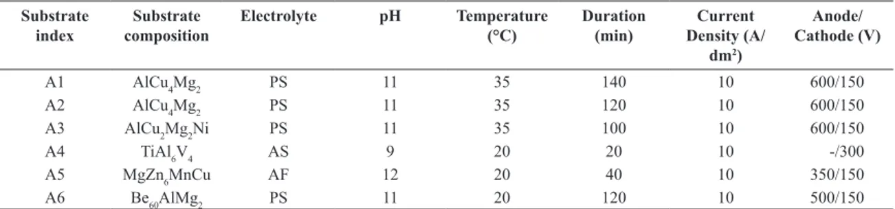
voltage pulses could be varied in the range 100-1000 V, at a pulse frequency range of 50-3000 Hz and within a current density range of up to 10 A/dm2. For all samples an initial power density of 200 V DC was established between the sample and the counter electrode to raise the current to 2 A/dm2, followed by application of an AC voltage coupled the DC and gradually increased to the required amperage. PEO conditions for each sample are shown in Table 1.
Following PEO, the oxide layers of samples A2 and A4 to A6 were enriched in Cr and Ni by chemical precipitation from the gas phase, while the samples were kept at 200 °C. For sample A3, a composite layer consisting of 20% Cr and 80% Cr3C2 was deposited by chemical precipitation from the gas phase, while the sample was kept at 300 °C. All samples were subjected to a inal polishing stage (until the apexes of the oxide-ceramic layer were visible), in order to remove excess layers of functional compounds and to re-distribute the remaining part uniformly over the sample surfaces. PEO parameters and surface post processing by chemical deposition were according to the layout in9. Comparative friction tests were carried out for the coated samples against hardened steel samples (ShKh15, hardness in the range of 653-697 Hv) were conducted in a ring-cylinder arrangement with intersecting axes for point contact. The steel sample was kept ixed and was pressed onto the moving non-ferrous alloy sample (ring). A small quantity of spindle oil was applied dropwise to the coated sample prior to each test. The test slip rate was 1.5-2.0 m/sec and a load of 60 N was constantly applied normal to sample contact. The result of every run was the average of ten measurements and the factors evaluated were the wear resistance, friction coeficient and load capacity of each sample. Wear resistance was estimated via weight loss the coated samples.
Micro-hardness tests were carried out on a Reinchert micro-indenter. The indentation transducer could apply loads in the range of 1-10000 ± 1 μN up to a maximum penetration depth of 3 ± 0.04 μm. In this study, nanoindentation tests were carried out under a 200 nm/s loading rate and a holding period of 2s. All experiments were performed in clean-room environment (45% humidity and ambient temperature of 23 oC).
X-ray diffraction (XRD) spectra were recorded on a Bruker D8-Focus diffractometer with nickel-iltered Cu Kα radiation (λ=1.5405 Å), 40 kV and 40 mA.
Percentage of porosity was determined by the Schwartz-Saltykov method11 from scanning electron microscopy (SEM) micrographs obtained on a Jeol 6380LV SEM
operating at 30 keV offering and average resolution of 3.5 nm at a working distance of 40 mm. Cr and Ni penetration in the oxide surface layers was established via SEM chemical analysis (EDS) utilizing a JED 2300 detector.
3. Results and Discussion
Based on macroscopic observations during the experiments, plasma conditions were achieved on the sample surface at approximately 140 V AC with the simultaneous release of water vapor generated by the exothermic PEO reaction. Metallographic examination of the sample cross-sections indicated the presence of discharge channels as dark dots distributed unevenly over the coating surface; the frequency of occurrence of the discharge channels appeared to decrease while their diameter increased with increasing AC voltage; these trends are similar to the ones observed for PEO processing of an 6061 alloy12. The variation of thickness, micro-hardness and open porosity of the POE-induced oxide coating is shown in Figure 1. For samples A1 to A3, average coating thickness decreased with decreasing processing time as the applied AC voltage remained constant. This is on a par with the generic observation of an increasing coating thickness with increasing AC voltage11. The POE rig did not allow a study of the rate of coating growth but there is mention of a linear-type growth at least in the irst stages of the PEO process12, where coating growth
Table 1. PEO experimental conditions. Electrolyte abbreviations are: PS - phosphate-silicate, AS - sulfate and AF -
aluminate-luoride.
Substrate index
Substrate composition
Electrolyte pH Temperature (°C)
Duration (min)
Current Density (A/
dm2)
Anode/ Cathode (V)
A1 AlCu4Mg2 PS 11 35 140 10 600/150
A2 AlCu4Mg2 PS 11 35 120 10 600/150
A3 AlCu2Mg2Ni PS 11 35 100 10 600/150
A4 TiAl6V4 AS 9 20 20 10 -/300
A5 MgZn6MnCu AF 12 20 40 10 350/150
A6 Be60AlMg2 PS 11 20 120 10 500/150
Figure 1. Experimental values of PEO-induced oxide layer
Augmentation of Wear-protective Coatings for Non-ferrous Alloys by the Addition of Cr and Ni Elements
2014; 17(6) 1487
results from the oxidation of molten aluminium outlow through the discharge channels13,14. The coating thickness of Al-containing sample A6 is roughly comparable with that of samples A1-A3 for similar PEO processing parameters. The reduced layer thickness in the case of the Ti-based (A4) and of the Mg-based (A5) alloys is considered to be principally owing to the reduced processing time; particularly in the case of sample A5, the increased pH is also deemed as having contributed to the samples low coating thickness. Open porosity was, on the whole, comparable over all samples but A4. X-ray analysis revealed principal peaks of the α- (alumina), β- and γ-Al2O3 (corundum) phases within the oxide layers, hence the effect of substrate composition on micro-hardness is principally related to formation of these phases. Based on Debye-Sherrer measurements of the relevant XRD peaks15, corundum dominates the surface just below 150 V AC, while the amount of α-Al2O3 increases with increasing voltage thereafter, due to the transformation of corundum to alumina in temperatures approaching 1000 °C16,17. The observed increase in micro-hardness as one moves from sample A3 to A1 can be explained on the basis of the γ- to α- Al2O3 transformation. In the current study, increasing processing time is taken to be equivalent to the effect of increasing AC voltage; for a suficiently high AC power throughput the temperature around the discharge channels may exceed 1000 °C; in this case it is plausible that corundum would transform into high-hardness alumina18. Equally possible is micro-hardening due to rapid quenching of the oxide layer towards formation of
the alumina phase11,19. Penetration depths of the Cr and Ni elements in the oxide layer are shown in Figure 2 and it appears to be a direct consequence of porosity. Wear behaviour, on the other hand, exhibits the inverse trend of that by micro-hardness. Sample A1 (not enriched in Cr or Ni) yields poor wear behaviour, that may be attributed to α- to the less durable β-Al2O3 phase transformation when the temperature in the locus of the discharge channels (normally taking place in the temperature vicinity of 2050 °C11). Not of the same order but distinctly higher that as compared to the rest of the samples is wear of Ti-based A4 alloy, for which the primary cause is the low Cr/Ni penetration coupled with the alloy’s inherent low wear durability. The lack of corundum or alumina-equivalent hardening phases in the case of the Mg-based A5 sample also yields poor wear behaviour despite the alloy’s relatively high Cr/Ni intake. The best overall wear performance was achieved in the cases of samples A2, A3 and A6. The former, was a successful combination of high micro-hardness based on γ/α-Al2O3, and of increased Cr/Ni penetration and resistance to wear. Sample A3 was treated under conditions similar to those of A2 but exhibited markedly lower Cr/Ni penetration. However, this feature was most likely balanced by the Ni content in the original alloy’s stoichiometry and thus the overall wear performance is near identical to that of sample A2. The latter sample was processed under similar PEO parameters and principally formed the same layer thickness as A2 and yielded a Cr/Ni uptake similar to that of samples A2 and A3. These results are roughly relected on the alloys’ friction coeficients, where all samples enriched with Cr/Ni greatly outperform reference sample A1 and this behaviour should be contrasted to the marked differences shown after the materials’ preprocessing by PEO and expressed as micro-hardness.
4. Conclusions
Addition of Cr and Ni elements into the oxide layers formed by PEO processing of a number of non-ferrous materials yielded a variety of micro-hardness and resistance to wear combinations. It was shown that a condition may exist in which both increased micro-hardness and good resistance to wear can be achieved, particularly in the case of Al-based alloys processed at a current density of 10 A/dm2. The overall optimum tribological behaviour obtained was that of the A4/ TiAl6V4 alloy. In conclusion, the test results have demonstrated the versatility of such composite coatings on various substrates.
Figure 2. Wear and friction coeficient achieved for the treated
alloy coatings.
References
1. Brandt G, Gerendas A and Mikus M. Wear mechanisms of ceramic cutting tools when machining ferrous and
non-ferrous alloys. Journal of the European Ceramic
Society. 1990; 6(5):273-290. http://dx.doi.org/10.1016/0955-2219(90)90019-C.
2. Makhlouf ASH. Casting out chromium: Non-toxic
pre-treatments protect magnesium and aluminium alloys. European
Coatings Journal. 2012; (3):16-20.
3. Antipas GSE. Review of gas atomisation and spray forming
phenomenology. Powder Metallurgy. 2013; 56(4):317-330.
http://dx.doi.org/10.1179/1743290113Y.0000000057.
4. Blau PJ. Embedding Wear Models into Friction Models.
Tribology Letters. 2009; 34(1):75-79. http://dx.doi.org/10.1007/ s11249-008-9395-1.
5. Bloyce A. Surface engineering of non-ferrous alloys.
Antipas
1488 Materials Research
6. Klocke F, Brecher C, Zunke R and Tuecks R. Corrective
polishing of complex ceramics geometries. Precision
Engineering. 2011; 35(2):258-261. http://dx.doi.org/10.1016/j. precisioneng.2010.10.001.
7. Salam Hamdy A, Beccaria AM and Temtchenko T. Corrosion protection of AA6061 T6 by fluoropolymer coatings in NaCl
solution. Surface and Coatings Technology. 2002;
155(2-3):176-183. http://dx.doi.org/10.1016/S0257-8972(02)00042-7.
8. Wilson S, Hawthorne HM, Yang Q and Troczynski T. Sliding and abrasive wear of composite sol–gel alumina coated Al
alloys. Surface and Coatings Technology. 2000;
133-134:389-396. http://dx.doi.org/10.1016/S0257-8972(00)00964-6.
9. Shatrov AS. Light alloy-based composite protective
multifunction coating. US. Patent EP 1231299 B1; 2012 Jan
18.
10. Curran JA and Clyne TW. Thermo-physical properties of
plasma electrolytic oxide coatings on aluminium. Surface and
Coatings Technology. 2005; 199(2-3):168-176. http://dx.doi. org/10.1016/j.surfcoat.2004.09.037.
11. Antipas GSE, Lekakou C and Tsakiropoulos P. Microstructural characterisation of Al—Hf and Al—Li—Hf spray deposits.
Materials Characterization. 2011; 62(4):402-408. http://dx.doi. org/10.1016/j.matchar.2011.02.001.
12. Wang K, Kim YJ, Hayashi Y, Lee CG and Koo BH. Ceramic coatings on 6061 Al alloys by plasma electrolytic oxidation
under different AC voltages. Journal of Ceramic Processing
Research. 2009; 10:562-566.
13. Sundararajan G and Rama Krishna L. Mechanisms underlying the formation of thick alumina coatings through the MAO
coating technology. Surface and Coatings Technology.
2003; 167(2-3):269-277. http://dx.doi.org/10.1016/S0257-8972(02)00918-0.
14. Xue W, Deng Z, Chen R and Zhang T. Growth regularity of ceramic coatings formed by microarc oxidation on Al-Cu-Mg alloy. Thin Solid Films. 2000; 372(1-2):114-117. http://dx.doi. org/10.1016/S0040-6090(00)01026-9.
15. Antipas GSE, Statharas E, Tserotas P, Papadopoulos N and Hristoforou E. Experimental and first-principles characterization of functionalized magnetic nanoparticles.
ChemPhysChem. 2013; 14(9):1934-1942. http://dx.doi. org/10.1002/cphc.201300161. PMid:23649714
16. Wei T, Yan F and Tian J. Characterization and wear- and corrosion-resistance of microarc oxidation ceramic coatings
on aluminum alloy. Journal of Alloys and Compounds.
2005; 389(1-2):169-176. http://dx.doi.org/10.1016/j. jallcom.2004.05.084.
17. Han-Hua W, Zeng-Sun J, Bei-Yu L, Feng-Rong Y and Xian-Yi L. Characterization of Microarc Oxidation Process on
Aluminium Alloy. Chinese Physics Letters. 2003;
20(10):1815-1818. http://dx.doi.org/10.1088/0256-307X/20/10/345.
18. Van TB, Brown SD and Wirtz GP. Mechanism of anodic
spark deposition. American Ceramic Society Bulletin. 1977;
55(6):563-566.
19. McPherson R. Formation of metastable phases in flame- and
plasma-prepared alumina. Journal of Materials Science. 1973;