Maria Antonieta Veloso Carvalho de OLIVEIRA(a)
Jessyca Figueira VENÂNCIO(a) Luís Henrique Araújo RAPOSO(b) Nelson BARBOSA JÚNIOR(c) João Carlos Gabrielli BIFFI(a)
(a)Universidade Federal de Uberlândia – UFU, School of Dentistry, Department of Endodontics, Uberlândia, MG, Brazil.
(b)Universidade Federal de Uberlândia – UFU, School of Dentistry, Department of Occlusion, Fixed Prosthodontics and Dental Materials, Uberlândia, MG, Brazil.
(c)Universidade Federal de Uberlândia – UFU, School of Dentistry, Department of Endodontics, Uberlândia, MG, Brazil.
Morphometric evaluation and planning of
anticurvature filing in roots of maxillary
and mandibular molars
Abstract: This study aimed to guide the planning of anticurvature iling
using pre-determined anatomical points on teeth to establish directions for proper implementation of the technique. Two hundred digital periapical radiographs of human molar teeth were selected and divided into two groups (n = 100): MX (maxillary) and MD (mandibular) molars. Mesiobuccal roots were considered for the MX group and mesial roots for the MD group. Pre-determined anatomical points required for planning the anticurvature
iling on the root canal path were located, and the distances between these points obtained. The anticurvature iling was simulated in two different protocols for each group, and the region of dentin removal and
the remaining dentin thickness were measured in the safety and danger
zones of the root canals. Statistical analysis was carried out at a signiicance
level of 5%. The distances between the anatomical points and the thickness
of remaining dentin showed signiicant differences when the two groups
were compared (p < 0.001). No signiicant differences were found between
the two experimental groups regarding the area of dentin removal at the
root region, but differences were detected in comparison with dentin
removal at the crown (p < 0.001). In terms of wear produced after simulation
of both anticurvature iling protocols, signiicant differences were veriied for all regions, except for the dentin remaining at the danger zone. The
radiographic location of anatomical points allows for planning and
implementation of controlled and eficient anticurvature iling and can be
performed in the same manner for maxillary and mandibular molars.
Keywords: Endodontics; Molars; Root Canal Preparation.
Introduction
According to the crown-down technique, root canal preparation can be divided into three steps: coronal access, radicular access, and apical
instrumentation.1 Coronal access is obtained with total removal of the
root pulp chamber roof and proximal wall convexities.1,2 Radicular access,
also known as anticurvature iling, should be carried out systematically
in the molar roots.3
The enlargement of root canals preceding apical preparation has many
advantages, such as eliminating dentin irregularities and providing
better performance for instruments and irrigating agents in the apical region.1,4 Furthermore, the correct establishment of the working length is
facilitated,5 which offers better control of the biomechanical preparation.6,7,8 Declaration of Interests: The authors
certify that they have no commercial or associative interest that represents a conflict of interest in connection with the manuscript.
Corresponding Author: João Carlos Gabrielli Biffi E-mail: [email protected]
DOI: 10.1590/1807-3107BOR-2015.vol29.0012
Submitted: May 05, 2014
Morphometric evaluation and planning of anticurvature filing in roots of maxillary and mandibular molars
The use of this technique also reduces the number of contaminants that can be extruded.9 Besides making
the action of instruments more effective, with lower risk of fractures, since adequate access and space are ensured,10 this technique also allows for better
compaction of gutta-percha in the apical region.11
Conversely, overlaring of root canals should be avoided, because it promotes weakening of dental structure and can result in perforations, mainly on
the furcal regions of teeth with curved root canals.12 The risk of perforation in areas with reduced dentin
volume, considered danger zones, can be reduced by directed iling to areas of higher dentin volume, or safety zones, as recommended in the anticurvature iling.3 This technique has been used since the 1980s,
irst with hand instruments and Gates-Glidden drills
and later with rotary instruments.10,12,13,14 However, recent studies have shown that there is no reduction in the perforation risk in danger zones (furcal region)
when anticurvature iling is performed, even with
Nickel-Titanium (NiTi) rotary systems.11,12
The excessive wear of coronal dentin also increases the risk of vertical root fractures in safety zones.11
The coronal chamber walls should be prepared only up to the extent necessary for the proper access of endodontic instruments.15 Maintenance of coronal
and root dentin, especially in the cervical area, is
essential to maximize the long-term results of the restorative procedures in endodontically treated
teeth,15 because the ability of a tooth to resist lateral
forces is directly proportional to the dentin thickness between the canal walls and root surfaces.16
The literature recommends that the files should have straight direct access to the apical region after anticurvature filing.1,6,9,10,11 However, there are no studies confirming the possibility of obtaining straight direct access to all canals without the removal of excessive dentin structure in the safety zone of the root. Several investigations have been carried out on the danger zones in curved
canals,11,12,17 but studies on the filing of the safety
zone are still lacking.
Thus, because of the importance of anticurvature iling in root canal preparation and the accidents that may occur during this procedure, the objective
of this study was to propose adequate planning for
effective anticurvature iling with reduced loss of dentin structure, taking into account pre-determined
anatomical points on teeth to establish directions for proper implementation of the technique.
Methodology
Two hundred digital periapical radiographs of human molar teeth were selected (gathered following informed consent according to a protocol approved by the Committee for Ethics in Research of the Universidade Federal de Uberlândia: #164.043).
The radiographs were obtained from records of
patients treated at a private practice ofice. All
radiographs were taken by the same operator
using Spectro 70X (Dabi Atlante, Ribeirão Preto, Brazil), a conventional x-ray unit associated with an intraoral digital x-ray sensor, CDR 2000 (Schick Technologies Inc., New York, USA).
The inclusion criteria consisted of radiographs of first and second maxillary and mandibular molars obtained in bucco-lingual incidence without distortions. Only radiographs from mandibular molars presenting overlapping of the mesial roots in which a single radiolucent root canal image was observed were considered. The radiographs
were then divided into two groups (n = 100): MX, maxillary molars; and MD, mandibular molars. The
mesiobuccal roots were considered in the MX group and the mesial roots in the MD group.
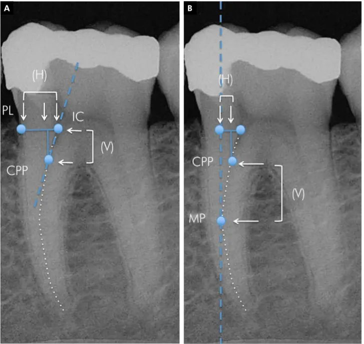
Image editing software, Adobe Photoshop 7.0 (Adobe Systems Inc., San Jose, USA), was used
for marking the canal paths of the roots and the
pre-determined anatomical points: IC, initial path of the root canal; CPP, critical penetration point of the ile in the canal; MP, maximum canal projection; and PL, periodontal root limit (Figure 1A). The
CPP point was evidenced by a straight line from the initial canal path up to the displacement of its
long axis, characterizing the beginning of the canal
curvature (Figure 1A). The MP point was located at the central point of the most convex part of the canal
path, evidenced by a vertical line tangent to this
To acquire numerical data for the marked points, we transferred the images to Microsoft Excel 2010 (Microsoft Corp., Washington, USA), in which a
millimeter grid was set over the images. The grid
had 0.5-mm markings, totaling 15 mm in length and 22 mm in height. The grid was set over the images
with the IC and PL points in the vertical zero limit and the MP point in the horizontal zero limit (Figure 1B). The distances (mm) between the anatomical
points were then obtained in the horizontal (H) and
vertical (V) directions (Figures 2A and 2B).
Simulation of the anticurvature filing
Two different anticurvature iling protocols were simulated in the present study: SF, straight access iling; and CF, conservative iling. SF was simulated through
a vertical line drawn from the crown to the maximum
canal projection in the vertical plane (MP) (Figure 3A),
A B
Morphometric evaluation and planning of anticurvature filing in roots of maxillary and mandibular molars
intended to allow for straight access of iles to the root
canal. CF was simulated to allow for straight access of endodontic instruments through a vertical straight line
parallel to the mesial root wall, connecting the occlusal
limit of coronal access (OL) to the MP point (Figure 3B).
The area of dentin removal in the root (DRR), for both iling protocols, was represented by a triangle formed by the IC, MP, and a point determined by the intersection between IC and PL, generated from the positioning of
the ile after determination of the anatomical points for the anticurvature iling (Figure 3). The area of dentin removal in the crown (DRC) for both iling protocols was
represented by a quadrangle or a triangle connecting the vertical line to the OL and IL points (Figure 3). The
DRR, DRC areas, and the remaining dentin distance after iling simulation were evaluated and quantiied in the mesial surface (RSZ, safety zone) and distal surface (RDZ, danger zone) with Image J (NIH, Bethesda, USA).
A B
The collected data were subjected to the Shapiro-Wilk
and Levene tests for the determination of normality and homogeneity. The comparison between the groups
before and after iling simulation was made by the t-test and the Mann-Whitney test. The data obtained after iling simulation were analyzed by one-way analysis of variance (ANOVA), with subdivided parcels and Tukey’s test for comparisons of both iling protocols inside
each group. The Spearman Rank Order Correlation
test was used to evaluate the correlation between the
data obtained after the iling simulations. All tests were performed at the 5% level of signiicance with SigmaPlot v.12.0 (Systat Software Inc., Chicago, USA).
Results
The data from the measurements of the distances
veriied between the anatomical points before the anticurvature iling simulation (Figures 2A and 2B)
Figure 3. (A) Simulated straight access filing (SF); (B) Simulated conservative filing (CF). Remaining dentin in the safety (RSZ) and danger (RDZ) zones (*yellow arrows), and areas of dentin removal in the root (*blue triangle) and in the crown (*white area).
Morphometric evaluation and planning of anticurvature filing in roots of maxillary and mandibular molars
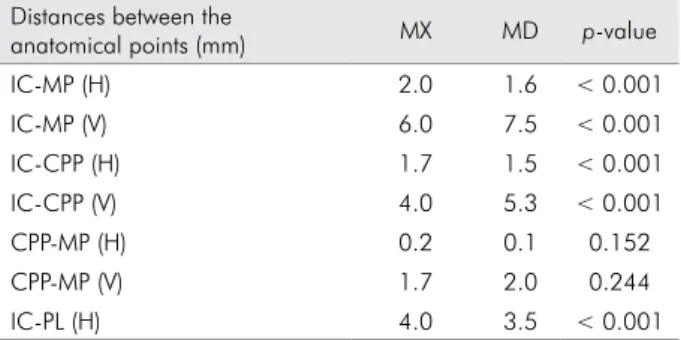
are shown in Table 1. In between-group comparisons,
significant differences were detected (p < 0.001),
with the MX group showing higher values in the
horizontal direction, while the MD group exhibited
higher values in the vertical direction.
The data from the measurements obtained after
the anticurvature iling simulation relative to the iling
area and remaining dentin (Figure 3) are shown in
Table 2. For between-group comparisons, signiicantly
higher values were found for the MX group (p < 0.001).
When the iling protocols were compared, signiicantly
higher values were found for the SF protocol (p < 0.001),
except for the dentin remaining in the safety zone.
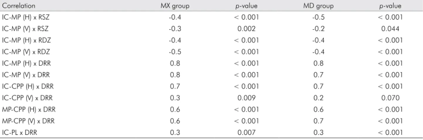
The correlations between the data veriied before
and after the anticurvature filing simulation are presented in Table 3. The distances between the anatomical points showed negative correlation to the dentin remaining in the safety and danger
zones in the root, and positive correlation to the
areas of dentin removal in the root (DRR) for both experimental groups.
Discussion
The anticurvature iling represents an important
technique for the endodontic treatment of curved
canals,3 though some care with the direction of the
instruments is required to prevent weakening of root dentin. Some anatomical parameters should be taken
into account in the planning of anticurvature iling, since anatomy imposes limits that, if correctly observed, will prevent excessive iling of the root structure.
Taking into account the anatomical points related
to the root canal path, as in the present study, can
allow for adequate planning of the anticurvature
iling. The critical penetration point (CPP) represents the initial curvature of the root canal path, in which endodontic instruments ind the irst obstacle during
canal penetration. This region can be located at any area of the canal that includes the initial canal
path (IC) and its maximum projection (MP), in the
mesiodistal (MD) and buccolingual (BL) directions
of the root. Its location is signiicant for the planning of anticurvature iling and, in this study, was a factor
in the results observed in the simulations performed. The CPP location was observed in the cervical third
in 57% of cases for the MX group and in 68% for the MD group, making its displacement necessary to the region of maximum projection of the canal,
allowing for approximation of the apical region. The
closer the CPP is to the root apex, the easier it will be to keep the original root canal path, due to the greater lexibility at the end of the ile. The literature
recommends that cervical pre-flaring performed before canal instrumentation should allow for free
straight access of iles up to the apex or to the initial
canal curvature.1,5,6,7,9,10,17 Following this precept, ile access at mesiobuccal canals in maxillary molars and
Table 1. Median distance values between the anatomical points in the vertical (V) and horizontal (H) directions related to groups of maxillary molars (MX) and mandibular molars (MD).
Distances between the
anatomical points (mm) MX MD p-value
IC-MP (H) 2.0 1.6 < 0.001
IC-MP (V) 6.0 7.5 < 0.001
IC-CPP (H) 1.7 1.5 < 0.001
IC-CPP (V) 4.0 5.3 < 0.001
CPP-MP (H) 0.2 0.1 0.152
CPP-MP (V) 1.7 2.0 0.244
IC-PL (H) 4.0 3.5 < 0.001
*IC: Initial path of the root Canal; MP: Maximum canal Projection; CPP: Critical Penetration Point; PL: Periodontal root Limit.
Table 2. Median values obtained after anticurvature filing protocols (SF, straight access filing; CF, conservative filing) re-lated to the thickness (mm) of the root dentin remaining in the safety zone (RSZ) and danger zone (RDZ) and the areas (mm2) of dentin removal in the root (DRR) and in the crown (DRC).
Median values
Filing protocol Region MX MD p-value
SF RSZ (mm) 2.0Aa 2.0Aa 0.066
CF RSZ (mm) 2.3Ba 2.0Bb 0.004
p-value < 0.001 < 0.001
SF RDZ (mm) 1.5Aa 1.5Aa 0.340
CF RDZ (mm) 1.5Aa 1.5Aa 0.340
p-value 1.000 1.000
SF DRR (mm2) 5.6Aa 5.2Aa 1.000
CF DRR (mm2) 4.8Ba 4.3Ba 0.224
p-value < 0.001 < 0.001
SF DRC (mm2) 12.1Aa 8.9Ab 0.002
CF DRC (mm2) 8.6Ba 6.6Bb < 0.001
p-value < 0.001 < 0.001
Table 3. Correlation of anatomical points and thickness of the remaining root dentin in the safety zone (RSZ), danger zone (RDZ), and area of dentin removal in the root (DRR) in the vertical (V) and horizontal (H) directions.
Correlation MX group p-value MD group p-value
IC-MP (H) x RSZ -0.4 < 0.001 -0.5 < 0.001
IC-MP (V) x RSZ -0.3 0.002 -0.2 0.044
IC-MP (H) x RDZ -0.4 < 0.001 -0.4 < 0.001
IC-MP (V) x RDZ -0.5 < 0.001 -0.4 < 0.001
IC-MP (H) x DRR 0.8 < 0.001 0.8 < 0.001
IC-MP (V) x DRR 0.8 < 0.001 0.7 < 0.001
IC-CPP (H) x DRR 0.7 < 0.001 0.7 < 0.001
IC-CPP (V) x DRR 0.3 0.009 0.2 0.070
MP-CPP (H) x DRR 0.6 < 0.001 0.6 < 0.001
MP-CPP (V) x DRR 0.6 < 0.001 0.7 < 0.001
IC-PL x DRR 0.3 0.007 0.3 < 0.001
mesial canals in mandibular molars would occur
only up to the initial canal curvature, represented
by the CPP point in this research. The extent of
anticurvature iling at only this point may promote the formation of steps in the canal path. Thus, iling extension until the maximum projection of the canal (MP) is suggested, since the initial barrier would be
overcome thereby.
The maximum canal projection (MP) represents the maximum vertical limit for the orientation of iling
on the outer walls of the root canal. The MP point was not coincident with the initial canal curvature (CPP) in 100% of canals from the MX group and in
99% from the MD group, being located at an average of 2.27 mm after the CPP. Following anticurvature filing simulation, the CPP was displaced to the MP, being located in the medium third in 89% of canals from the MD group and in 85% from the MX
group. This represents the displacement of the initial canal curvature from one canal third to another.
Additionally, the greater the distance between CPP and MP points, the higher the root dentin area removed in the anticurvature iling, for both the horizontal
and vertical directions.
The occlusal limit point (OL) located at the tooth
crown is the limit for the anticurvature iling in the
occlusal regions. This limit was considered after complete removal of the roof of the pulp chamber and pulp horns in the crown opening. A straight line connecting the OL and MP points of the canal path determined the positioning and inclination
of the file after anticurvature filing (Figure 3B).
In the simulations, it was observed that the file inclination presented various angles, depending on the
characteristics of each tooth. This fact demonstrates that it is not always necessary for canals to be accessed
with iles at a vertical straight line after anticurvature iling, as suggested by some studies.1,5,6,7,9,10,17
The straight access of iles in a vertical line after anticurvature iling simulation was possible in only 29% of mesiobuccal canals from maxillary molars and in 46% of mesial canals from mandibular molars. In the other cases, reaching straight ile access would
require excessive removal of dentin from coronal and
cervical third regions, which can lead to weakening of tooth structure, thus increasing the risk of vertical
root fractures (Figure 3A).
In comparison of wear produced by the two
anticurvature iling protocols for both experimental groups, the area of dentin removal at the danger zone (RDZ) was found to be unaffected. However,
the different filing protocols influenced the area of dentin removal in the crown and root in the safety zone (RSZ). The straight access filing (SF) promoted increased dentin removal compared with
the conservative iling (CF), showing total wear (crown and root) superior to 36% of the MX group and to 20% of the MD group. Since both iling protocols moved
the critical penetration point (CPP) to the maximum
Morphometric evaluation and planning of anticurvature filing in roots of maxillary and mandibular molars
produces less removal of crown and root dentin in
the safety zone (RSZ), reducing the risk of fractures
by tooth weakening.
Despite the increased area of dentin removal observed for the MX group compared with the MD
group with the same anticurvature iling protocol,
the dentin remaining in the two zones of the root was
similar for both groups. The inluence of anatomical
differences between the groups was detected only for
dentin removal in the crown, reinforcing the assertion
that there is no need to perform different anticurvature
iling techniques for maxillary and mandibular molars,
particularly if the anatomical points presented in this study are taken into consideration.
The distance between the initial canal path and the
maximum projection (IC-MP) inluenced the remaining dentin thickness after the anticurvature iling simulation.
It was observed that the greater the distance in the vertical
and horizontal directions, the lower the thickness of
the remaining dentin following the procedure in the danger and safety zones of the root. The increased distance between the IC-MP points is of clinical concern
in these two root zones. In the safety zone, this thickness presents no perforation risk, but may weaken dentin by excess iling in an attempt to obtain vertical straight access of iles. In the danger zone, the possibility of
perforation with periodontal exposure was observed more frequently in the mesiobuccal roots of maxillary
molars, which presented a 0.6-mm remaining thickness at the danger zone after anticurvature iling simulation.
Therefore, it is suggested that when a great distance between the initial path and its maximum projection (IC-MP) is observed radiographically, the anticurvature iling should be initiated with manual or rotary iles
of reduced conicity to increase the control of ile orientation and iling in the danger zone. In addition, excessive iling in the safety zone during attempts at straight canal access should be avoided because, in these cases, the ile will present distal inclination.
The research design of this study presents some
intrinsic limitations, since it was conducted during simulations of different anticurvature iling protocols in
digital radiographs of clinically obtained maxillary and mandibular molars. Future studies that overcome these limitations with laboratory and clinical evaluations of
the parameters presented will be of beneit.
Conclusion
The radiographic location of the critical penetration point (CPP) and its relation to the other anatomical points described are essential for maintaining the original root canal path and for planning the
anticurvature iling.
Conservative anticurvature iling seems the best option, since it may remove reduced amounts of crown and root dentin and, even with anatomical differences, can be performed in the same manner
for maxillary and mandibular molars.
Correlation was observed between the distance of the anatomical points and the amount of root dentin
removal after the anticurvature iling.
Acknowledgments
The authors would like to acknowledge to the
Fundação de Amparo à Pesquisa do Estado de Minas Gerais
(FAPEMIG) for the inancial support of the project
References
1. Goerig AC, Michelich RJ, Schultz HH. Instrumentation of root canals in molars using the step-down technique. J En -dod. 1982 Dec;8(12):550-4.
2. Hülsmann M, Peters OA, Dummer PMH. Mechanical prepa -ration of root canals: shaping goals, techniques and means. Endod Topics. 2005 Aug;10(1):30-76.
3. Abou-Rass M, Frank AL, Glick DH. The anticurvature filing method to prepare the curved root canal. J Am Dent Assoc. 1980 Nov;101(5):792-4.
4. Constante IGT, Davidowicz H, Barletta FB, Moura AAM. Study of the areas and thicknesses of mesiobuccal root canals prepared by three endodontic techniques. Braz Oral Res. 2007 Apr-Jun;21(2):118-26.
5. Iqbal A, Akbar I, AL-Omiri MK. An in vivo study to deter -mine the effects of early preflaring on the working length in curved mesial canals of mandibular molars. J Contemp Dent Pract. 2013 Mar;14(2):163-7.
6. Tan BT, Messer HH. The effect of instrument type and preflaring on apical file size determination. Int Endod J. 2002 Sep;35(9):752-8. 7. Pécora JD, Capelli A, Guerisoli DMZ, Spanó JCE, Estrela C.
Influence of cervical preflaring on apical file size determina-tion. Int Endod J. 2005 Jul;38(7):430-5.
8. Silveira LFM, Silveira CF, Castro LAS, César Neto JB, Martos J. Crown-down preflaring in the determination of the first apical file. Braz Oral Res. 2010 Apr-Jun;24(2):153-7.
9. Camargo EJ, Zapata RO, Medeiros PL, Bramante CM, Ber -nardineli N, Garcia RB, et al. Influence of preflaring on the accuracy of length determination with four electronic apex locators. J Endod. 2009 Sep;35(9):1300-2.
10. Ehrhardt IC, Zuolo ML, Cunha RS, De Martin AS, Kherla -kian D, Carvalho MC, et al. Assessment of the separation incidence of Mtwo files used with preflaring: prospective clinical study. J Endod. 2012 Aug;38(8):1078-81.
11. Wu M-K, Van der Sluis LWM, Wesselink PR. The risk of fur -cal perforation in mandibular molars using Gates-Glidden drills with anticurvature pressure. Oral Surg Oral Med Oral Pathol Oral Radiol Endod. 2005 Mar;99(3):378-82.
12. Akhlaghi NM, Kahali R, Abtahi A, Tabatabaee S, Meh -rvarzfar P, Parirokh M. Comparison of dentine removal using V-taper and K-Flexofile instruments. Int Endod J. 2010 Nov;43(11):1029-36.
13. Mahran AH, AboEl-Fotouh MM. Comparison of effects of ProTaper, HeroShaper, and Gates Glidden burs on cervical dentin thickness and root canal volume by using multislice computed tomography. J Endod. 2008 Oct;34(10):1219-22. 14. Sanfelice CM, Costa FB, Só MVR, Vier-Pelisser F, Bier CAS,
Grecca FS. Effects of four instruments on coronal pre-en -largement by using Cone Beam computed tomography. J Endod. 2010 May;36(6):858-61.
15. Ree M, Schwartz RS. The endo-restorative interface: current concepts. Dent Clin North Am. 2010 Apr;54(2):345-74. 16. Raiden G, Koss S, Costa L, Hernández JL. Radiographic mea
-surement of residual root thickness in premolars with post preparation. J Endod. 2001 Apr;27(4):296-8.