Nelson Miguel Costa Pinto
Licenciado em Engenharia InformáticaDatabase-Based IP Network Routing
Dissertação para obtenção do Grau de Mestre em
Engenharia Informática
Database-Based IP Network Routing
Copyright © Nelson Miguel Costa Pinto, Faculdade de Ciências e Tecnologia, Universi-dade NOVA de Lisboa.
A Faculdade de Ciências e Tecnologia e a Universidade NOVA de Lisboa têm o direito, perpétuo e sem limites geográficos, de arquivar e publicar esta dissertação através de exemplares impressos reproduzidos em papel ou de forma digital, ou por qualquer outro meio conhecido ou que venha a ser inventado, e de a divulgar através de repositórios científicos e de admitir a sua cópia e distribuição com objetivos educacionais ou de inves-tigação, não comerciais, desde que seja dado crédito ao autor e editor.
Este documento foi gerado utilizando o processador (pdf)LATEX, com base no template “novathesis” [1] desenvolvido no Dep. Informática da FCT-NOVA [2].
A c k n o w l e d g e m e n t s
I would like to express my gratitude to my advisor, José Legatheaux Martins, for his guidance, advice, support and dedication, and for all the knowledge that he transmitted to me throughout the preparation of this dissertation and in the course of my academic journey.
A b s t r a c t
The Software-Defined Networking (SDN) approach has the goal of simplifying net-work management. SDN uses a logically centralized approach to enable simpler netnet-work programmability and simplify the network architecture. SDN is in general associated with the OpenFlow protocol, which standardizes communication between a controller and network devices. Alternatively, a database approach could be used to tackle data exchange between controller and network devices. This solution requires the installation of a database server inside each switch, and replicas of those local switches databases, in the controller. The database approach offers several potential advantages over OpenFlow
such as higher level of abstraction, flexibility and the use of mature implementations of standardised database protocols to propagate information events and commands.
The purpose of this work is to apply a Database-Based Control Plane (DBCP) for SDN networks on a wide area environment. The objective is to implement a replacement of the control plane of a wide area network, currently achieved using a link-state protocol such as OSPF or IS-IS, by an SDN approach based on similar techniques as the ones used in [4].
We conducted an experiment, which we called IP-DBCP, that consisted of the defini-tion of data models and the construcdefini-tion of an SDN network with database replicadefini-tion as the means of communication between one controller and multiple switches. To this end, a switch was developed, using OpenSwitch software as a logical hardware layer, that is ca-pable of executing a MySQL database management system, load it with its characteristics and collect data related to its network neighbourhood. A controller was also developed that executes a MySQL database management system with the replicated databases of all switches. The controller uses those replicated databases to construct routing rules, using a shortest-path algorithm. Ultimately we tested the correct functioning of the solution and evaluated the convergence time by performing network state changes and compared the results with the ones found in traditional link state protocols.
R e s u m o
Uma abordagemSoftware-Defined Networking(SDN) tem como objetivo simplificar a gestão da rede. SDN utiliza uma abordagem logicamente centralizada de forma a permitir a programação da rede de forma mais simples e simplificar a sua arquitetura.
SDN é geralmente associado ao protocoloOpenFlow, que padroniza a comunicação entre o controlador e os dispositivos da rede. Em alternativa, uma abordagem de base de dados pode ser usada para lidar com a troca de dados entre um controlador e os dispositivos da rede. Esta solução necessita da instalação de um servidor de base de dados dentro de cada switche réplicas dessas bases de dados locais, no controlador. A abordagem com bases de dados oferece diversas potenciais vantagens como um maior nível de abstração, flexibilidade e o uso de implementações maduras e padronizadas de protocolos de bases de dados para propagar eventos e comandos.
O propósito deste trabalho é de aplicarDatabase-Based Control Plane(DBCP) para re-des SDN de grande âmbito. O objetivo é implementar um substituto de umcontrol plane numa rede de computadores de grande âmbito, atualmente conseguido utilizando proto-colos como oOSPFouIS-IS, por uma abordagem SDN baseada em técnicas semelhantes às usadas em [4]. Realizámos uma experiência, que chamámos de IP-DBCP, que consistiu na definição dos modelos de dados e na construção de uma rede SDN com replicação de base de dados como o meio de comunicação entre um controlador e váriosswitches. Um switchfoi desenvolvido, usando osoftwareOpenSwitch como uma camada de hardware lógico, que é capaz de executar um sistema de gestão de base de dados MySQL, carregá-lo com suas características e recolher dados relacionados com sua vizinhança de rede. Um controlador também foi desenvolvido sendo que executa um sistema de gestão de base de dados MySQL com as bases de dados replicados de todos os switches. O controlador usa essas bases de dados replicadas para construir regras de roteamento, usando um algoritmo de caminho mais curto. Testámos o funcionamento correto da solução e avalia-mos o tempo de convergência, realizando alterações no estado da rede e comparando os resultados com os encontrados em protocolos tradicionais delink state.
Palavras-chave: Software-Defined Networking, Bases de dados, Redes de computadores
C o n t e n t s
List of Figures xiii
1 Introduction 1
2 Related work 5
2.1 Introduction . . . 5
2.2 Software-Defined Networking . . . 6
2.2.1 Data plane . . . 7
2.2.2 Control Plane . . . 9
2.2.3 Management plane . . . 10
2.3 Design approaches and challenges. . . 10
2.3.1 Reactive vs Proactive Controller Policies . . . 10
2.3.2 Scalability concerns . . . 10
2.3.3 SDN applications . . . 11
2.4 Database approach versus OpenFlow . . . 12
2.5 Open Shortest Path First . . . 13
2.6 Conclusion . . . 14
3 Database-Based Control Plane 15 3.1 Database-Based Control Plane . . . 15
3.2 Components of the DBCP architecture . . . 18
3.3 Network model and other assumptions . . . 21
3.4 Data model . . . 21
3.4.1 Conceptual Data model . . . 22
3.4.2 Logical data model . . . 25
3.5 Conclusions . . . 28
4 IP Network Database-based Control Plane implementation 29 4.1 Introduction . . . 29
4.2 Switch. . . 31
4.2.1 OpenSwitch . . . 31
4.2.2 Switch deployment . . . 33
4.3 Controller . . . 38
4.3.1 Network Control Services implementation. . . 39
4.4 Physical data model . . . 45
4.5 Database replication. . . 46
4.6 The Bootstrapping sequence . . . 48
4.7 Conclusions . . . 49
5 Prototype evaluation 51 5.1 Introduction . . . 51
5.2 Evaluation methodologies and environment . . . 51
5.3 Evaluation . . . 52
5.3.1 Evaluating the system . . . 52
5.3.2 Results . . . 55
5.3.3 Evaluation Conclusions. . . 58
6 Conclusions 63 6.1 Concluding Remarks . . . 63
6.2 Future Work . . . 64
L i s t o f F i g u r e s
2.1 Plane oriented view of the SDN architecture . . . 7
3.1 OpenFlow network. . . 17
3.2 DBCP network. . . 17
3.3 DBCP view of switches and controller . . . 19
3.4 Data flow view between controller and switches. . . 22
3.5 Modular view of the data model . . . 24
3.6 An entity–relationship diagram for the base data model. . . 26
4.1 Complete view of the implemented system components . . . 30
4.2 Production network: Virtual networks created to connect switches running on virtual environments . . . 34
4.3 A modular view of SwitchDBCP . . . 35
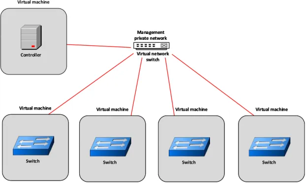
4.4 Management network: A Virtual network connecting switches and the con-troller . . . 39
4.5 A modular view ofSwitchDBCP . . . 40
4.6 The bootstrapping sequence of a switch . . . 49
5.1 The production network topology . . . 53
5.2 Database replication time using different SymmetricDS software configurations 55 5.3 Network convergence events flow after an interface state change . . . 57
C
h
a
p
t
e
r
1
I n t r o d u c t i o n
Management of traditional networks can be complex, time consuming and error prone. This is due to the fact that networks can consist of a large number of vendor-specific devices which are usually closed systems with limited interfaces. Often, policy enforce-ment and system manageenforce-ment must be done directly on the infrastructure, device by device. Additionally, with traditional network protocols, the control plane is distributed and scattered by all devices, therefore, managers have difficulty achieving a coherent and
logical view of the network.
The Software-Defined Networking (SDN) approach has the goal of simplifying net-work management [5]. SDN uses a logically centralized approach to enable simpler network management and simplify its control plane.
In an SDN controlled network, the control plane functions are concentrated in one or more control servers, known as SDN controllers. Switches have only flow tables (the data plane) and no other intelligence besides a control module, that fills the tables entries as ordered by the controller. The usage of SDN approaches are being widely tested and the success of its application is clear in a data centre, where hundreds of switches (with no control plane functionality) are controlled by logically centralized controllers.
Outside this natural setting, an SDN approach faces additional challenges related to the extra latency between controller and switches, heterogeneity of the system compo-nents and greater difficulty in setting up a logically centralized view at scale.
SDN is in general associated with the OpenFlow protocol, which standardizes com-munication between a controller and network devices in an SDN environment. An SDN architecture approach doesn’t necessarily need to use OpenFlow, other solutions are pos-sible to setup the dialogue between switches and controllers.
database server inside each switch, and replicas of those local switches’ databases, in con-trollers. The controller drives the switches by making updates to its replica databases, and the switch transmits information or its state the other way around. Control algorithms executions are triggered by the switches’ database updates. This database approach has several potential advantages over OpenFlow: higher level of abstraction; higher flexibil-ity since device enhancements are translated into database models’ modifications; low level custom communication protocols are replaced by standardised database protocols (query, updates and replication); well defined semantics in the dialogue between the different systems components (Eg. transactions can be used); the protocols, model and
mechanisms are well understood and mature implementations are available. This kind of system architecture has yet to be tested in a wide area network because of its intrinsic challenges.
The purpose of this work is to test and assess a database approach to implement a replacement of the control plane of a wide area network, currently achieved using a link-state protocol such as OSPF or IS-IS, by an SDN approach based on similar techniques as the ones used in [4].
In a data centre, dialogue and state synchronization among switches and controllers is easier since latency is very low. In the wide area we will face an extra challenge re-lated to higher and heterogeneous latencies, harder to implement controller availability requirements and higher scalability.
The main contributions of this work are:
• The definition of the data model required to implement the approach
• Study the implementation challenges
• Make a preliminary assessment of the performance challenges brought by this ap-proach.
• Highlight its advantages and drawbacks.
This document is structured this way:
• Chapter 2 will introduce Software-Defined networking, by giving the motivations for its creation and explaining its main principles. It also introduces the main components and views of an SDN and after, design approaches are discussed such as controller policies, scalability concerns and SDN applications.
• Chapter 3 presents Database-Based Control Plane approach (DBCP). It describes the DBCP model as well the data models it requires.
• Chapter 5 presents the tests and results measured with the IP-DBCP prototype.
C
h
a
p
t
e
r
2
R e l a t e d w o r k
2.1 Introduction
Traditional computer networks can be characterized as a layered architecture composed of three planes: the data, control and management planes. The management plane may in-clude software services which allow for functionality control, configuration and network policy definition. The control plane enforces those polices. It represents the protocols used to generate the network topology and data plane forwarding tables. The data plane represents the network devices and is responsible for implementing the policy by for-warding data accordingly.
In traditional networks, the data and control planes are coupled and embedded in the same devices, allowing them to take decisions on their own. This highly decentralized ar-chitecture contributed to the success of the Internet as it is today, assuring a fundamental requirement for operability: network resilience [11].
However, this comes at a cost of increased complexity: the tight coupling of data and control planes (vertically integrated) means that decisions about data flows are made onboard the device. The deployment of new functionality and policy enforcement must be done directly on the infrastructure which, together with the fact that there is a lack of a common interface to all devices and the presence of dynamic environments, requires a huge amount of time and can be error prone.
To cope with the lack of functionality, and the increased control requirements, spe-cialized devices such as firewalls, middle boxes and intrusion detection systems may be inserted into the networks which may further increase network design and operation complexity [11][16].
Networks can be composed of a large number of different, vendor-specific, routers,
The need for interoperability between different devices leads to the creation of specific
protocols which may take years to develop and to evolve to new functionality [11][4].
2.2 Software-Defined Networking
Software-Defined Networking (SDN) is a proposal for a “programmable network”, break-ing the vertical integration of network devices by decouplbreak-ing the control from the data planes, with the goal of simplifying network management and enabling innovation and evolution [11][16].
The Open Networking Foundation (ONF) defines SDN as follows: “Software-Defined Networking (SDN) is an emerging architecture that is dynamic, manageable, cost-effective,
and adaptable, making it ideal for the high-bandwidth, dynamic nature of today’s applica-tions. This architecture decouples the network control and forwarding functions enabling the network control to become directly programmable and the underlying infrastructure to be abstracted for applications and network services.” [5]. The SDN architecture is based on three principles [7]:
The decoupling of traffic from control:As described before, an SDN characteristic
is the decoupling of the data and control planes which is a precondition for logically centralized network control. Network devices become simple forwarding elements. This decoupling also allows for separated evolution and software life cycles.
Logically centralized control:An SDN major characteristic is the logical
centraliza-tion of control. As followed by the decoupling of the data and control planes, a single entity (which could be distributed) called an SDN controller or a Network Operating System (NOS), orchestrates resources and provides abstractions to facilitate the program-ming of forwarding devices.
Programmability of network services:This principal goal is to provide agility
through-out information exchange between a client and a SDN controller allowing configurations before and during the lifetime of a service.
These principles are subject to interpretation and may lead to different
2 . 2 . S O F T WA R E - D E F I N E D N E T WO R K I N G
Data Plane Data Plane
Management plane
Network applications
Network applications
Management plane
Network applications
Network applications
Control Plane Control Plane
Figure 2.1: Plane oriented view of the SDN architecture
2.2.1 Data plane
The data plane, also considered a forwarding abstraction, is the first layer of an SDN network and is directly associated with the network infrastructure. It is represented by several interconnected forwarding devices, each containing a set of traffic forwarding and
processing instructions. Its main role is to implement the forwarding decisions made by the control plane. A characteristic that differentiates it from traditional networks is
the removal of intelligence from the devices. They become simple forwarding devices and must receive instructions from the controller plane through an open interface called the southbound interface. The SDN data plane can be described by two layers: Network infrastructures and Southbound interface [11][6][7].
Network infrastructure
Network infrastructure is the composition of interconnected hardware and software forwarding devices such as routers, switches and virtual switches. The centralization of intelligence on the controller transforms these network devices in simple packet forward-ing entities that must receive instruction from the controller on how to operate. Network devices may still contain a minimal set of management and control functions allowing the necessary configurations to establish communication between devices and the controller [11][6].
Southbound interface
There are several approaches such as OpenFlow, ForCes and database. [11][16][7][4]. We will only refer the first one because it is the most known and the last because it plays a crucial role in this work.
Openflow
OpenFlow, managed by the Open Networking Foundation (ONF), is a communica-tion protocol which standardizes informacommunica-tion exchange between controllers and data plane devices. OpenFlow requires a compatible switch or router which may exist as two variations: a pure or a hybrid device. A pure device has no intelligence outside the bound-aries of OpenFlow, a hybrid has both support for OpenFlow protocol but maintains other traditional protocols allowing it to function outside an SDN environment.
The OpenFlow implementation has two abstractions: the controller communication and the flow tables. The flow tables consist of flow entries defining how packets from a flow should be forwarded in a switch and are composed of three parts: 1) Matching rules; 2) Actions for matching packets; 3) Statistical counters. Using the arrival of a packet to a switch as an example, the header fields are extracted and compared to the matching rules. If the result is a match, the appropriate actions for that match are taken for the packet. If the lookup process returns a miss, which could mean the switch is facing a new flow, it should use a default rule which is usually set to send the packet to the controller to be processed. The communication between the controller and data plane are made using the OpenFlow protocol which sets a number of messages, understood by both parties. [16][6][7].
Database approach
Alternatively, OpenFlow can be replaced by a replicated and distributed database approach as described in [4]. The principal characteristic of this alternative is to install a database server inside each switch and maintain replicas of those databases in the controller. Database techniques and protocols are then used to update both switches’ and controllers’ databases. A controller may force new rules on to a switch by making updates in its corresponding database replica. A switch may also transmit information or its state the other way around. Control algorithms executions are triggered by the switches’ database updates.
This database approach has several potential advantages over OpenFlow [4]:
• The use of standard database synchronization protocols, abstracts the details of data transfer between entities and conceals the low-level protocol details from the developers, who use an higher level of abstraction;
2 . 2 . S O F T WA R E - D E F I N E D N E T WO R K I N G
• Well defined semantics in the dialogue between the different systems components
(e.g. transactions can be used...);
• Low level custom communication protocols are replaced by standardised database protocols (query, updates and replication);
• The protocols, model and mechanisms are well understood and mature implemen-tations are available.
• Low level details of packet processing are left to the switch control software, which increases separation of concerns.
This approach has only been tried in a data centre environment, which means there is an incomplete understanding of how this may behave in a different environment such as
a wide area network. It needs to be taken into account that every switch on the network must maintain a database in order to be able to communicate and maintain configura-tions.
2.2.2 Control Plane
The control plane, considered the brain of the network, implements what is also known as the Network Operating System (NOS), solves the networking problems, provides services and creates abstractions to lower-level interconnecting devices. It facilitates network management by means of a logically centralized control and programmatic interfaces to the network.
The controller must understand the network topology under its domain and take decisions accordingly, based on policies defined by the management plane. Example of those are: through which switches and links should a packet be forward or is the packet authorized to go to the requested destination.
Controllers don’t require special hardware equipment as they can be deployed on traditional servers and platforms using traditional software. They have three commu-nication layers: the southbound interface, already described before, which standardizes communication between the controller and data planes and the Northbound and East-bound/Westbound interfaces [11][16][6].
2.2.2.1 Northbound
2.2.2.2 Eastbound/Westbound
Some SDN implementations may require the deployment of multiple distributed con-trollers across the network. The Eastbound/westbound is a horizontal layer of communi-cation providing the means for inter-controller communicommuni-cation. Such layer may be used for controller state synchronization and may vary depending on the implementation. There are no standards for Northbound, Eastbound and Westbound communications [11].
2.2.3 Management plane
The management plane uses the abstractions provided by the controller plane and is composed by services and applications. An application can be perceived as instructions that controls a set of resources provided by the controller [11][7].
2.3 Design approaches and challenges
As part of the description of the SDN architecture, there are some architectural design aspects that should be considered.
2.3.1 Reactive vs Proactive Controller Policies
When a network device receives a packet and gets a miss from the lookup process on the flow tables, a decision has to be made by the controller about that packet. The point is to forward that packet through the network until it reaches its destination or it leaves the network on the controller domain. In this scenario, the controller may adopt one of two policies: Reactive or Proactive. With a reactive policy, the controller installs a new flow entry on the network devices allowing the packets on that flow to be forward. With each new flow, setup time has to be considered and can be lengthened by geographically dispersed remote controllers. Also, with this policy, the controller becomes a bottleneck because the network work rate depends on the controller response performance. The proactive policy tries to anticipate the arrival of new flows and pre-installs multiple generic rules on all devices. Although this may cause a loss of precision, this approach may significantly reduce the number of new flow requests to the controller [16].
2.3.2 Scalability concerns
2 . 3 . D E S I G N A P P R OAC H E S A N D C H A L L E N G E S
requests to the controller by implementing proactive policies with the cost of loss of precision and flexibility.
A distributed set of controllers can be seen as an alternative to mitigate this problem. Although it might seem beneficial, those controllers now require synchronization to allow the same view of the network. Consistency algorithms imposes design trade-offs. As the
network grows, the use of strong consistency may lead to the reduction of throughput and increased response time. Alternatively, one could use weak consistency with the cost of possible loss of precision during synchronization periods. On flow based architec-tures, the initial flow setup delay may impose some scalability concerns. The constant appearance of new short lived flows, plus the use of a reactive policy by the controller, could mean a constant network device-to-controller communication overhead. Also, the memory available inside the switches is limited which raises scalability concerns with the increase of flow entries [16][25].
2.3.3 SDN applications
Data centres are an agglomerate of a large number of servers and network devices, usually inside a large building, where latency is small. Most data centres are shared among several different customers and constitute a multi-tenant environment.
Data centres have to cope with constantly changing environments, requirements and the need to enforce multiple network policies. Data centres also face challenges such as the need for optimization of resources, definition of QoS, power saving, provisioning, security and flexibility.
The low latency environment in a data centre provides a realistic environment for the deployment of a Software-defined Network. One of the pillars of an SDN is logically cen-tralized control. In a data centre, a controller or cluster of controllers, could be installed in the network connected to all network devices. This allows the controller to obtain a global view of the network topology. Such an approach enables the programmability of policies and configurations at a single point, avoiding the application of those policies directly to the infrastructure, which could be expensive and error prone due to the large number of different devices. With an SDN approach, network devices would become
sim-ple forwarding entities orchestrated by the controller. The controller may push new flow entries on to devices to deal with incoming traffic through proactive or reactive policies.
The global view of the controller enables it to optimize resources when needed, such as power saving.
2.3.3.1 SDN in the wide area environment
Wide area networks interconnect multiple local area networks and are characterized by its geographical span. Therefore, a characteristic of this kind of network is the increased latency of communication between network devices. Also, due to its role, it has a require-ment of a high availability since down time could be costly. Wide area networks must also be able to scale to withstand increased demands from its edges.
An SDN approach could be used in the wide area, just like other environments such as data centres, to enable simpler network management and simplifying its control plane. In a data centre, dialogue and state synchronization among switches and controllers is easer since latency is very low. In the wide area we will face extra challenges related to the higher and heterogeneous latencies. The switch to controller communication has increased latency, consequence of it geographical position, which has to be considered. Also it is harder to implement controller availability and higher scalability requirements.
Moreover, in order to deal with the challenges and avoid a central point of failure, the logicically centralized control of the network requires a hierarchical and recursive view of the control plane [13].
A production SDN for the wide area environment, was designed by Google and de-scribed in [10]. This work shows an SDN deployment for a wide area network (WAN) that connects Google’s data centres across the planet. Consisted on an hybrid approach with support for existing routing protocols and OpenFlow.
2.4 Database approach versus OpenFlow
A database approach for controller and switch communication was considered in the work [4]. This work discussed the construction of an SDN environment for data centres context, that achieved interoperability of different vendor network hardware devices. The
work focussed on the controller and switch communication.
For the design of the architecture, they considered that the OpenFlow protocol wasn’t sufficient enough to answer their requisitions and the need for interoperability. They
stated that because OpenFlow is a low level protocol, only devices that support it, can be inserted on the system. Also, different vendor switches require special OpenFlow
protocol adaptation in order to integrally make available all the features supported by switches’ ASICs to the controller. As this process of adaptation becomes complicated, the need for a higher level of abstraction arises. OpenFlow was also considered not flexible enough to freely evolve to new features.
2 . 5 . O P E N S H O R T E S T PAT H F I R S T
also separates the replication mechanisms from the network services. This approach ab-stracted the implementation details of data synchronizing from the network operations and presented a clear state consistency model that could be used by the whole system.
With this database approach, the challenge resided on constructing a data model that could be generic enough to be supported by all vendors and still allow the implementation of their specific hardware optimizations.
The flow definition processes was left to the switches themselves. The controller computes the control plane details and shares them with the switches using the Open vSwitch Database (OVSDB)[21] protocol. By doing so, they considered an higher level of abstraction.
A reference is made to a constraint of the database approach. Although new fea-tures could be expressed as a change to the data model, the controller and switch still require new code to consolidate the new capabilities. Also there is the case where dif-ferent switches could be running different data model versions, which requires further
consideration.
2.5 Open Shortest Path First
Open Shortest Path First (OSPF) is a routing protocol for IP networks, based on link-state technologies, that distributes network state information between routers belonging to the same Autonomous System (AS) [14].
The OSPF protocol produces, in a decentralized way, the routing rules that routers use to forward IP packets. Each router running OSPF contains a global view of the network and produce its own routing rules using a shortest path algorithm.
The global view of the network is built by the combined effort of every router. Routers
use the Hello Protocol to periodically send announcement packets to it’s neighbours through all router’s interfaces. The Hello protocol establishes and maintains neighbour relationships between routers and probes bidirectional communication between neigh-bours. This way neighbours may form an adjacency. It also allows the detection of router/link failures.
Each router contains a database, referred to as the Link-State Database, that describes the autonomous system topology. This database is composed by the router’s local hard-ware state and it’s neighbour relationships. The database is complemented with link-state advertisements (LSAs), produced by every router, consisting of each router’s local hard-ware state and it’s neighbour relationships and thus fully describing the network.
Based on the link-state database each router creates a shortest path tree with it self as root. This tree gives a path to every other reachable router and their locally associated IP prefixes and defines the best next-hop. When a topology change occurs, the changes are flooded and every router computes new shortest path trees based on the newly updated link-state database.
An Autonomous System can be dived in special groups called areas. These areas were conceived to break down the scale of the AS into multiple groups, reducing the convergence time and scale of the traditional routing protocols and creating isolation between different regions. Areas may be composed by multiple networks interconnected
by routers. At the edge of these areas, special routers called “Area Border Routers” work on forwarding traffic outside the area when needed. To maintain multiple areas in a
single AS, a backbone area exists composed by multiple interconnected routers that communicate with the areas border routers. This backbone is called the area 0. Each area runs an independent version of OSPF assuring the convergence of routers inside the area. The backbone also runs an independent version of the algorithm.
There is another link-state protocol, on which OSPF got inspiration, the IS-IS protocol, which is popular among ISPs.
Although the notion of areas makes part of both protocol definition, most large scale ISPs, only use one area since the introduction of areas introduces constraints and extra complexity on the network management processes.
2.6 Conclusion
In this chapter we introduced the main concepts behind Software-Defined Network as well as the most complex issues brought by this approach. We also analysed and compared two southbound protocols, namely OpenFlow and database-based approaches.
We also showed that some IGP protocols, namely OSPF and IS-IS, also rely on cen-tralized visions, replicated in each router, to create its own forwarding rules. In order to extend the information flooded, or to change the way forwarding rules are computed, it would require a new version of the protocol and its deployment in every router of each vendor.
C
h
a
p
t
e
r
3
Da t a b a s e - Ba s e d C o n t r o l P l a n e
In this chapter we start by introducing the Database-Based Control Plane (DBCP) ap-proach and compare it with other southbound protocols such as OpenFlow. We present the reasons for the construction of DBCP and discuss its’ components and models. We also present a particular experiment based on the implementation of this model, the IP Network Database-Based Control Plane (IP-DBCP). Finally, the chapter defines the conceptual data model and logical data model that we introduced in the IP-DBCP.
3.1 Database-Based Control Plane
SDN was introduced with the promise of simplifying network management. To achieve this goal, it centralizes the control and network management on a central controller. This is in contrast with the traditional approaches where network control is decentralized and scattered across all switches. The communication between controller and switch in SDN is an essential part of the network operation. It’s through this communication layer, also called southbound communication, that controllers and switches exchange data required for the network operation. The importance of this communication layer raised the need for definition of new protocols in response to this requirement.
One popular southbound protocol is OpenFlow. For SDN networks, it strictly defines the information exchange between controller and switch. OpenFlow changes the way switches work by stripping it offany intelligence and requires the controller to define all
controller to the switch and upcalls from the switch to the controller.
The controller implements a distributed flow management service that defines the appropriate flow entries for each switch it controls. These flows entries are constructed based on the controllers global view of the network topology. The network topology discovery and setup is fully enforced by the controller. The controller may also collect statistics about the functioning of the network. Figure3.1shows an example of an Open-Flow network.
OpenFlow is widely used but still presents some limitations. As the work in [4] states, the use of low level semantics for the definitions of data exchange makes OpenFlow inflexible, over-specified in low level details and hard to evolve, not allowing for a clear separation of concerns and abstractions.
As a consequence, an OpenFlow switch is completely dependent on a controller to leverage any hardware optimization. Moreover, OpenFlow lacks a synchronization model when involving multiple switches. There is a lack of specification that guarantees the ordering and consistency of the data exchange operations across multiples switches.
In this work, we attempt to test a different approach to controller and switch
com-munication by dealing with some of the OpenFlow challenges, using databases concepts inspired in [4]. In this work we also consider this database approach on a wide area (WAN) environment as opposed to the work presented in [4] that is applied inside a data centre.
To assess both challenges, we started with the definition of Database-Based Control Plane (DBCP), to replace a traditional shortest-path IP routing algorithm, with a central-ized approach using SDN and database techniques.
The DBCP approach aims to elevate the level of abstraction by using databases schemas, models and replication protocols as the way of sharing data among controllers and switches. The use of standard database techniques, abstracts the details of data transfer between entities and conceals the low-level protocol details from the developers, who use an higher level of abstraction. This approach increases flexibility because there is no need to evolve the communication protocol to support new features, which can be now made directly available on the database schema. Also, database replication protocols models and mechanisms are well understood and mature implementations are available. Those protocols offer a well defined distributed semantics.
3 . 1 . DATA BA S E - BA S E D CO N T R O L P L A N E Controller O p e n F lo w O p e n F lo w Flow table Flow table Flow table Network State Tables
Figure 3.1: OpenFlow network.
Network database Switch database Switch database Switch database Controller D a ta b a se S yn c h ro n iz a ti o n
Figure 3.2: DBCP network.
In order to demonstrate that the DBCP approach is realistic in the wide area network, it is necessary to define the adequate data models to build the abstractions required for the necessary network control goals. However, it is also necessary to demonstrate that the database protocols used to replicate data among the different components are able to
converge in a timely manner at least as good as, if not better, than the ones implemented by traditional purpose-built network protocols. On top of the paradigm change, the DBCP architecture must still be designed to support essential WAN requirements such as packet routing and network management.
To explain in more detail and to give a more general perspective about how DBCP is characterized, DBCP is composed of switches and controllers. Switches communicate between themselves using links connected by their interfaces, and also communicate with the controllers through its local database. State and configurations changes are con-verted to database operations locally, which are then synchronized with the controllers. Switches maintain a local view of their directly connected neighbours and forward pack-ets based on decisions received from the controller. Controllers are independent entities that use information from their local database to produce routing decisions and enforce configurations.
An SDN characteristic is the removal of intelligence from the switches. OpenFlow completely removes the intelligence from switches. As opposed to OpenFlow, in DBCP this removal is considered only partial. Switches lose the capability of reacting to con-figuration changes and knowledge of a global view of the network. On the other hand, switches still maintain a local vision of the neighbourhood, so the topology gathering pro-cess in DBCP is considered distributed on the switches as opposed to being centralized in OpenFlow, since this approach is still essentially a local one.
The switches outsource the capabilities of producing routing rules, to the controller. The controller produces routing data based on the network topology and propagates it to the switches.
Network Database-Based Control Plane"(IP-DBCP). The objective is to define and develop a first approach of an SDN setting, having controllers and switches communicate through their individual databases. We focus on the essential aspects of the wide area routing that enable its functioning, leaving more specialised components, such as QoS and traffic
engineering, for future developments.
3.2 Components of the DBCP architecture
DBCP has two main components: switch and controller. Controller and switches commu-nicate through database replication techniques over the network. This communication layer is called southbound communication. The rest of the chapter describes DBCP in more detail as well as the components and what was taken into consideration for the implementation.
Switch
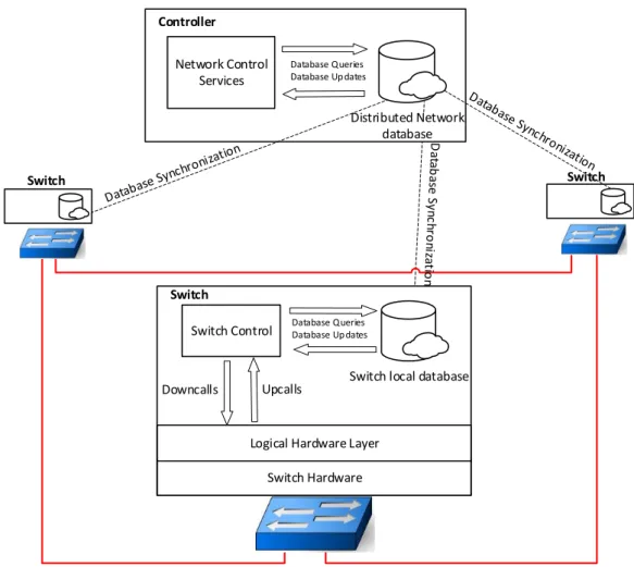
In DBCP a switch is characterized by the partial removal of the control plane. As opposed to the OpenFlow definition, in DBCP the switches still conserve a part of their control plane. As will be clearer below, all distributed control plane functions are, as with OpenFlow, under the responsibility of the controller, however most centralized control plane functions are still with switches in DBCP. Some of the control plane responsibilities are delegated to the controller using a database management engine. Figure3.3presents DBCP view of switches and controllers. A switch can be modularized by three compo-nents: a database, the switch control software and the logical and physical hardware.
The database is the divergent element on switches, as compared to other SDN ap-proaches. As stated before, this database is used as the base element of communication with the controller. For that reason, it is essential that the switch has the knowledge to be able to populate that database with the required data. Additionally, it must be able to drive its hardware, on the basis of information received from the controller. This database component is part of a database management system and requires mechanisms for database replication.
3 . 2 . CO M P O N E N T S O F T H E D B C P A R C H I T E C T U R E
Switch Hardware
Switch Control
Switch
Database Queries Database Up dates
Upcalls
Downcalls Network Control
Services
Database Queries Database Up dates Controller
Switch local database Switch
Distributed Network database
Switch
Logical Hardware Layer
Figure 3.3: DBCP view of switches and controller
The hardware components are the low level mechanisms that enable packet forward-ing, flow creation and capability configurations such as interfaces states. It can be further distributed in a logical hardware layer and the real hardware.
A switch may be connected to multiple other switches and hosts through its existing interfaces and links. The switch’s main role is to receive and forward incoming packets to the requested destination or next-hop. To achieve this, while not relaying on a spe-cific control plane, it operates on the base of the controller’s commands which arrive to the switch as database updates. For the purpose of this experiment, the data models used to implement routing include the routing information base (RIBs) and should also encompass interfaces, their state and neighbourhood.
To implement IP routing it is assumed that there is a level of abstraction on the switch that knows how to interpret the routing table, in order to generate a corresponding flow table. Also, packet forwarding mechanisms components and interface management are also assumed to be present.
on networks to be forward to the destination. The creation of new routing rules is de-pendent on a complete view of the network, in order to make them precise and efficient.
To create a global view, protocols like OSPF detect state changes through purpose-build protocols that periodically monitor all interfaces on switches and flood the changes to all other switches.
We could adopt a solution similar to the one available in most OpenFlow controller/switches. In general, OpenFlow upcalls signal to the controller the available interfaces, their sta-tus and state change. However, discovering which neighbours are available via each interface is implemented by the controller, in general using a process identical to the implementation of Link Layer Discovery Protocol(LLDP) [9].
We decided that switches in DBCP should be in charge of discovering their neighbours by reason of separation of concerns. It is possible to implement at the switch level, this discovery process almost in a centralized process. Therefore we decided to consider this a low level requirement the controller may ignore. This neighbour information collected by switches is considered for the database model of controller and switches.
A switch view of the world can be summarized to its database and directly connected neighbours. The switch view of the controller is abstracted by the database. Instead of communicating directly with a controller, a switch sees the database as repository of knowledge that enables its operation.
Controller
In DBCP, a controller, just like in other SDN approaches, is the central pillar of the architecture. The controller has the purpose of orchestrating the switches’ activity and maintaining a global view of the network based on information originated from switches. Figure 3.3also shows the role played by the controller on the network. A controller is characterised as containing the replicated state of all switches’ databases and a Network Control Services module. The controller’s goal is to use those databases to build a global view of the network and apply configuration rules to all switches that enable the appro-priate routing of packets. The Network Control Services are able to query the replicated databases to build a global view of the topology, configure switches and execute shortest path algorithms using the database’s information. Those services must also be able to react to database changes and apply corresponding solutions. This reaction is critical for the convergence time.
For routing, we opted for the implementation of a pro-active approach. The controller creates beforehand the necessary routes based on the current knowledge of the network topology and inserts those new routes on the database. Compared to a specific approach this does not require that, when a new packet arrives, that packet is sent to the controller to be analysed. We opted for this approach to follow what’s already done with link-state protocol and to essentially simplify the routing procedure.
3 . 3 . N E T WO R K M O D E L A N D O T H E R A S S U M P T I O N S
Southbound communication
As stated before, the action of communicating between controllers and switches and vice-versa is reduced to local databases updates. The communication is abstracted by mak-ing all operations seem local. The databases then use replication protocols to synchronize any update that occurs.
3.3 Network model and other assumptions
The implementation presented in this dissertation focuses on wide area network environ-ments. Since these networks are complex, some assumptions about the implementation were made in order to scale down this experiment.
The solution at this phase will only consider IPv4 routing and neighbour discovery, leaving IPv6 for future implementations. Also, unlike OSPF or IS-IS which supports the creation of multiple areas [14], it was decided that in the context of this work, an area free environment would only be considered.
To facilitate the construction of the experiment, we opted for the implementation of two separate networks: the management and production networks. The production net-work corresponds to all the links interconnecting all switches and focuses on transporting production packets. The management network is a private network, connecting switches and controllers, with the purpose of only being used for management data.
For switch-to-switch connectivity of the production network, we assumed only point-to-point links. Point-point-to-point links are characterized by connecting only two nodes.
Link and switch failures may occur on a network, which must be dealt with in order to maintain the network resilience. For this experiment, we assume only link and switch failures.
SDN implementations usually deploy more then one controller. On this experiment only one controller is considered.
3.4 Data model
This section presents the DBCP data model. A data model is a design model that describes data, data relationships, data semantics, and consistency constraints. It provides the means to describe the design of a database.
3.4.1 Conceptual Data model
A conceptual data model is an abstract view of the data model. It describes the semantics and main concepts within certain subjects.
For the definition of the data model it is important to first consider the requirements. These requirements are critical to build the data model since they define the rules and conditions necessary to achieve the defined objectives. At this phase, only the base data model is discussed. The base data model is composed by essential information that is common to the controller and switch.
The essential goal of the data model in DBCP is to be the base that supports the communication from switch to controller and vice-versa. For this reason, the base data model must support the distributed insertion and retrieval of data by both a controller and switches.
This base data model must be designed in such a way that the same model can be deployed on both a controller and a switch. It must also be generic enough to support basic IP routing in the network functioning and still allow different configurations to be
enforced by the controller. Also, the base data model must take into consideration the network model and the assumption previously presented.
So, for the definition of the base data model, we must first analyse what data is re-quired to be exchange between controllers and switches. This data will drive the base data model design.
Controller
Distributed Network database
Switch
Switch local database
Switch hardware characteristics Switch hardware configuration Switch neighbourhood data updates Routing data updates
Switch hardware configuration.
Figure 3.4: Data flow view between controller and switches.
3 . 4 . DATA M O D E L
Switch
As discussed before, the vision of a switch became restricted to their lower level func-tioning and direct neighbourhood, which consequently leads to the need for intervention by the controller in the definition of the guidelines for the switch functioning. Namely, in what concerns all data deployment of the network (as a whole). In this sense, for the functioning of a switch we can group data into two groups:
• Switch hardware configuration.
• IP Routing data
These two data groups essentially answer the lack of intelligence caused by the SDN design. A switch expects a controller to decide about its configuration. The hardware configuration group composes all the data produced by the controller that changes the hardware status of the switch.
The routing data group, considers all the data related to packet forwarding. A switch expects to receive, from a controller, all routing related data since it has no global network view.
Controller
From the controller’s perspective, the network is constituted by a set of distributed switches. To fulfil this vision of the network, the controller needs to understand the characteristics and capabilities of each switch as well as their neighbourhood status. This way, we can group the data required by the controller as follows:
• Switch hardware characteristics
• Switch hardware configuration.
• Switch neighbourhood data
One of the key and fundamental roles of the controller is to produce routing data. To this end, it requires a global view of the network topology. In DBCP the network view acquisition is distributed across every switch. A controller constructs a global view by collecting the individual neighbourhood view of each switch.
The controller also needs a view of the characteristics of every switch. This neces-sity is based on the vision that individual capabilities of each switch must be taken into consideration for the creation of routing rules. In this context, these characteristics are followed by related configurations and statistics that enable knowledge of the current state of the switch.
A modular view
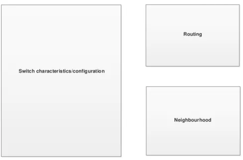
the routingbase, often called the Routing Information Base or RIB. Figure3.5shows a modular view of the base data model.
Switch characteristics/configuration
Neighbourhood Routing
Figure 3.5: Modular view of the data model
The switch characteristics/configurations:this module makes reference to all switches’
available characteristics and possible configurations. TheCharacteristicsof a switch can be grouped by all the information that describes a switch, or as its features and capa-bilities. An example of this kind is the physical address of a switch or the number of interfaces available, followed by all their individual characteristics. TheConfiguration part corresponds to all the values that map to possible configurations that may impact switch operations. Such status changes can be a change of an interface’s state or name. This information is important to the controller to enable better knowledge of all features supported by network devices and to allow possible state configurations changes to the switch. This module also includes statistics.
Routing:this module corresponds to the routing data. It would contain all
informa-tion relevant to routing, produced by the controller and used as the guiding map for the switches forwarding mechanisms.
Neighbourhood:this module’s main function is to gather all neighbour related
3 . 4 . DATA M O D E L
3.4.2 Logical data model
A logical data model is an implementation of a conceptual data model, presenting a more detailed view of a data model. It describes entities, attributes and relationships but abstracts implementations details.
For DBCP we start by defining an Entity-Relationship Model (ER). The Entity-Relationship Model is composed of entities, relationships and attributes that represent a description of interrelated things of interest.
For the definition of the ER model we consider the assumptions and requirements defined in the conceptual model. The base data model is divided into three groups:The switch characteristics/configuration,Routing,Neighbourhood. We started by defining the entities and relationships that play a role inside each of those groups. An entity is an object that is distinguishable from other objects.
Switch characteristics/configurationsencompasses entities that support the switch char-acteristics and configurations. First of all, we defined an entity calledswitch. Other pillar of switch management are the interfaces configurations. Although an interface is a char-acteristic of a switch, we consider it as an independent entity. In this sense we add a new entity called interfaces. This entity serves as the repository for all data related to interfaces in a switch. This entity needs to maintain a relationship with theswitchentity. This relationship is expressed as one-to-many. It is considered that an interface has to necessarily be associated with one switch, but a switch has more than one interface.
The routing module hosts data related to routing and the forwarding of packets in DBCP. It is assumed there is only one entity calledrouting. This entity hosts data related to several routes. Because the network model defines the network connections as being point-to-point, it can be assumed that there exists only one other switch behind an inter-face. So it is possible to define routing rules based only on the exiting interfaces. This originates a relationship between theinterfacesand theroutingentity. This relationship is mandatory for theroutingentity and can be expressed as one-to-many. One interface can be associated with many routing entries but one route can only be associated with one interface. Also, every route must be associated with a switch, representing the switch it belongs to. So, a one-to-many relation is the solution, where one switch can have multiple routes and one route belongs to one switch.
This is a one-to-many relation where a neighbour switch can be associated with many interfaces, assuming that two switches can be connected through two different links and
interfaces, and an interface can only be associated with a neighbour switch, as for the limitation of point-to-point interfaces.
1 N N 1 N 1 Iden tifier Iden tifier Name Name Chassi s Physsical add ress Chassi s Physsical
add ress Manag me nt IPManag me nt IP
Name Name Typ e Typ e Observed Link State Observed Link State
Link Spee d Link Spee d
Route P refix Route P refix
Pre fix Len gth Pre fix
Len gth WeightWeight
Chassi s Physica l Add ress Chassi s Physica l Add ress Switch characteristics/configuration Neighbourhood Routing Identifie r Identifie r Switch Neighbour Switch Routing Admini strative Link State Admini strative Link State Identifie r Identifie r Descrip tion Descrip tion Physsical add ress Physsical add ress Statistics Statistics Remote interface name Remote interface name
Remote in terface Physica l a ddress Remote in terface Physica l a ddress
MTU MTU 1 N N 1 Interface
Figure 3.6: An entity–relationship diagram for the base data model.
Entities can have attributes. An attribute is a property of an entity. In the following list we will describe those attributes, reason to its introduction and their importance to the data model.
Figure3.6shows an ER diagram with entities, relationships and attributes.
Switch
Identifier- Each switch has an identifier. This identifier allows the unique
identifi-cation of a switch on the network and the data model.
Name- The name of the switch. The objective of this attribute is to assign a human readable name to identify the switch.
Chassis Physical address- This attribute relates to the chassis’s MAC address of a
3 . 4 . DATA M O D E L
Management IP- The management IP is the IP address assigned to the switch on
the management network.
Interface
Identifier- Each interface has an identifier. It allows the unique identification of an
interface on the network.
Name- A name of the interface. The objective of this attribute is to assign a human readable name to identify the interface.
Type- The type of interface.
Description- A textual description of the interface.
Administrative Link State- The administrative link state relates to the configured
desired state of the interface. Its purpose is to enable the configuration of an interface’s state. This is the state that controller imposes.
Observed Link state - The observed link state is the actual state of the interface
reported by the switch.
Physical address- The MAC address of an interface.
Link Speed- The link speed of with an interface.
MTU- The Maximum Transmission Unit (MTU) of the interface.
statistics- Encompasses data produced by the switch that characterizes the
function-ing of the interface.
Routing
Identifier- Each routing entry has an identifier. This identifier will be unique for
each route entry and allows unique identification of an route on the network.
Route Prefix- The network destination IP address.
Prefix Length- The IP prefix length of the network destination.
Weight- A weight associated with this route entry.
Neighbourhood
Chassis Physical address- Represents the MAC address of the neighbour switch.
Remote interface physical address- Represents the physical address of the remote neighbour interface.
The above presented model has been established in an iterative way, being influenced by the implementation options presented in the next chapter. It is worth noting that this model has been established after the analysis of available RFC [2] [3].
3.5 Conclusions
C
h
a
p
t
e
r
4
I P Ne t w o r k Da t a b a s e - b a s e d C o n t r o l P l a n e
i m p l e m e n t a t i o n
4.1 Introduction
This implementation is an experiment, based on the DBCP model discussed in the pre-vious chapter, and consists of the development of a system that is capable of testing database protocols as the means for communication between a controller and switches and, at the same time, support the implementation of real IP packet forward and network management mechanisms on a wide area network.
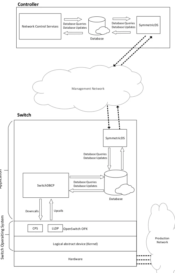
The implementation of this experiment consisted of the development of a controller that contains a local database and is able to produce routing rules, and a switch that also contains a local database. Both implement all the necessary tools that enables the opera-tion of the network by using their installed databases as the means of communicaopera-tions. Figure4.1shows an overview of the completed system architecture.
Switches were implemented as devices running OpenSwitch OPX operating system as a logical hardware abstraction on a virtual machine environment. OpenSwitch OPX offers
programmability interfaces that allow the control of a network device and the extraction of configuration, lower level hardware details and network details. The implemented switches are able to forward IP packets, and collect their neighbourhood state using the LLDP protocol.
Switches execute a database management system using a pre-defined data model that stores data related to its underneath capabilities, statistics and also data inserted by the controller. Switches run a control software called SwitchDBCP that intermediates the flow of data between OpenSwitch OPX services and the database.
Management Network
Database
Logical abstract device (Kernel)
Switch Database Queries Database Updates Upcalls Downcalls OpenSwitch OPX S w it c h O p er a it in g S y st em A p p li c a ti o n
Network Control Services
Database Database Queries Database Updates Controller SymmetricDS Database Queries Database Updates SwitchDBCP SymmetricDS Database Queries Database Updates CPS LLDP Hardware Production Network
4 . 2 . S W I T C H
and theNetwork Control Servicessoftware that manages data from the database and pro-duces routing rules based on the network topology. These routing rules are inserted in the controller’s database and propagated to the switches by the replication protocols.
Switches and the controller communicate with each other using the management network emulated in a virtual machine environment. The communication is achieved through the insertion of data into their local database and the use of SymmetricDS software, deployed on both controller and switch, that enables the replication of the database’s state. SymmetricDS is orthogonal to the database to separate, as much as pos-sible, the implementation of the switch and controller from the replication mechanisms since we think that an alternative replication substrate will be necessary in the future and is being designed right now.
Switches use the production network to forward packets to their destination.
To achieve the implementation of the purposed solutions the following tasks were pursued:
• Preparing an OpenSwitch OPX image based on one from [19].
• Integration of OPX virtual machines with VMware and the creation of custom vir-tual networks.
• Implementation ofSwitchDBCPcontrol software.
• Implementation of the data model schema based on OpenSwitch data model and launching of MySQL databases on switches and controller.
• Integration of SymmetricDS software, on switches and controller, with MySQL databases and a replication model.
• Implementation of theNetwork Control Servicessoftware on the controller.
Each of these tasks, as well as the related implemented solutions, will be described on the following sections.
4.2 Switch
4.2.1 OpenSwitch
OpenSwitch OPX provides to this experiment an abstraction of hardware details, allowing us to focus on the implementation and testing of the mechanisms supporting communication between controller and switches.
OpenSwitch, being a conventional Linux operation system, enables the execution of custom-made applications and the use of a wide range of software that is suitable for this implementation. These features are essential to deploy a database management system and related protocols. Furthermore, the use of OPX services helped us use already implemented and tested Linux IP stack network features for packet forwarding.
OpenSwitch OPX has several layers, starting with the hardware. It is currently avail-able in Linux platforms as well as in a range of Dell switches[20]. Thus it is easy to build virtual network devices in a virtual machine or container-based environment. Although OPX OpenSwitch allows testing by virtualization, a similar result is possible on a concrete hardware switch as well as using software-based routers.
On top of the hardware, a standard Linux distribution runs alongside OPX services.
The Control Plane Services (CPS) [17] is an object-centric API, provided by OPX, that enables an interaction between client applications and the OPX platform control and network abstractions. This API was crucial for the implementation, since it provided a way of interacting with OPX services by enabling the retrieval of switch network and hardware details and also the enforcement of configurations. Alternately, networking features could be accessed using the Linux standard API. However, with the former approach, the IP-DBCP software stack can run directly on any hardware platform based on OPX.
The CPS API uses YANG. YANG is a modular data modelling language created to standardize the definition and configuration of the network device characteristics. The YANG language is defined in [1]. Each attribute is represented by a tree path over the YANG model. The YANG model used by the CPS API influenced the design considerations and the definition of the physical data model.
The neighbourhood search and acquisition process was achieved using the Link Layer Discovery Protocol (LLDP) [9]. The LLDP protocol was used to fulfil the requirement for searching and constant updating of the neighbourhood state for the purpose of building the network topology.
LLDP is a vendor-neutral layer 2 discovery protocol used by network devices to ad-vertise their capabilities and identify neighbours. It periodically sends LLDP frames to neighbour devices. Those frames contain information, such as the switch’s chassis MAC address or management IP address. Receiving devices collect and store those frames on a management information database (MIB) and complete the received data with local information such as the interface from which the frame arrived.
4 . 2 . S W I T C H
In our opinion, the right place to implement LLDP in our environment is at the switch level, since it deals with details that only concerns the switch itself and doesn’t require any distributed coordination. OpenSwitch OPX includes an implementation of the LLDP protocol.
4.2.2 Switch deployment
For the deployment of switches we opted for the use of VMware virtual environment[23]. This option allowed a faster development of the software modules and offers flexibility
in testing and evaluating the developed components on a larger scale. We decided to use independent virtual machines to represent each device. Each virtual machine runs OpenSwitch OPX operating system.
OpenSwitch OPX has support for hardware virtualization. The OpenSwitch commu-nity provides an OPX version that simulates basic hardware functionality. For the devel-opment of this experiment an image was used, that is available on [19], as a starting point. This image is composed of a base Linux(Debian) operating system with pre-installed OPX services and software modules and their requirements, such as Python for example. Several updates were made to the base image in order to support the dependencies of the experiment. The following software was installed:
Python 2.7.9
Python is used by the CPS API and was also used for the implementation of SwitchDBCPand theNetwork Control Services.
MySQL Server 5.7.2
This version(or higher) is required in order to support the creation of multiple triggers with the same action on the same table. This is a requirement to support bothSwitchDBCPand SymmetricDS triggers that monitor the database.
Python MySQL connector 2.1.7
The MySQL Python connector that supports MySQL and Python versions.
SymmetricDS 3.9.2
The latest version available at the time of implementation was installed.
Java 8
Java 8 is a requirement of SymmetricDS version 3.9.2 .
LLDP 0.95-1