The Wire Drawing Mechanics of Near-Equiatomic NiTi SMA
André da Silva Antunesa , Osmar de Sousa Santosa, Leonardo Kenji Fudo Naitoa, Odair Dona Rigob,
Jorge Otuboa*
Received: October 18, 2017; Revised: January 24, 2018; Accepted: February 27, 2018
The wire drawing mechanic of Ti-49.82Ni (at. %) Shape Memory Alloy (SMA) was investigated through the true stress-strain curves and drawing stresses. The tensile tested solution treated wire
presented a four steps elongation at temperatures below the austenite finish temperature (AF), and a
conventional one-step behavior above the martensite deformation temperature (MD). The tensile yield stress for the formation of detwinned martensite (DTM) or stress-induced martensite (SIM) increased as the testing temperature increased; however, for larger deformation, the behavior reversed. The
efficiency of drawing work, which is the ratio of uniform work to total work, increased from 10% for
0.07 mm2.mm-2 area reduction at 25 °C to 50% for 0.21 mm2.mm-2 at 110 °C. Therefore, wire drawing
temperature and area reduction should be combined to increase the efficiency, taking into account the desired properties with reasonable workability. Furthermore, transformation work should be considered
on wire drawing shape memory alloys as phase transformation occurs in temperatures below MD.
Keywords: NiTi, Shape Memory Alloys, Wire Drawing, Uniform Work, Transformation Work.
*e-mail: jotubo@ita.br
1. Introduction
The NiTi SMAs are a special class of materials with
properties such as shape memory effect (SME) and/or superelasticity (SE)1,2. Those properties provide the capability
of recovering from the high amount of strain upon heating
(SME) or upon mechanical load relieve (SE)2,3. Those
non-conventional properties are useful in applications such as microgripper4, actuators, microactuators5, stents, surgical
implants, dental arc-wire6,7 and endodontic files, as well as
automotive, naval, and aerospace technologies6.
NiTi shape memory alloys are produced by EBM8 or
by VIM, and then thermomechanically transformed into
bars and wires. Thermomechanical processing influences the shape memory and/or superelasticity properties of NiTi
alloys2,9-11. Because most of the applications of NiTi SMAs
are in wire form, the end stage of the fabrication process is frequently done by wire drawing. Therefore, understanding the drawing mechanics is an important issue to broaden applications of NiTi SMAs.
In wire drawing of conventional metals and alloys,
the total drawing work per unit volume is given by the uniform work, redundant work, and frictional work. The only work that effectively contributes to deform the wire is the uniform work, while redundant work is the energy
spent to shear deform parallel to die surface to compensate
for the difference in mass flow gradient from the wire axis to surface, and frictional work is the energy spent due to
friction between die surface and wire surface. The total
work is equal to the drawing stress, and the uniform work
is the area under the true stress-strain curve for a respective strain or area reduction12.
The deformation under tensile or compressive load of conventional metallic materials develops in two steps: initially the elastic deformation and then the plastic deformation. In contrast, NiTi SMAs have non-conventional mechanical behavior at temperature below MD (maximum temperature at which the martensite phase can be stress induced)2,13,
deforming in four steps: initially the elastic deformation of
pre-existing phase (martensite (M), austenite (A) or a mix of M and A); next a pseudoplastic deformation associated with
the martensite variants reorientation or detwinned martensite (DTM) (if the previous phase is M) or the formation of stress-induced martensite (SIM) (if the previous phase is A); then the elastic deformation of martensite (DTM or
SIM); and finally the plastic deformation10. Therefore, it is
reasonable to expect that, at least in the first drawing pass of work hardening, NiTi SMAs will have distinct drawing
mechanics, due to the possible occurrence of the transformation
of M to DMT and/or phase transformation from A to SIM
during mechanical deformation compared to conventional metallic materials.
aITA Shape Memory Alloy Research and Technology Group - ITASMART, Instituto Tecnológico de
The literature related to the wire drawing of SMAs is very scarce and no information related to phase transformation occurring during wire drawing has been reported. Wu et al.14
concluded that a multi-pass drawing must be performed at drawing temperatures around martensite start temperature (MS). The objective of this work is to investigate the influences
of previous (pre-existent) phase on the wire drawing of
near-equiatomic NiTi SMA. It is industrially important to optimize the wire drawing setup and then reduce the energy consumption.
2. Experimental Procedure
The starting Ti-49.82Ni (at.%) ingot of 50 mm in diameter produced by vacuum induction melting (VIM) (hereafter-called NiTi) was hot rolled down to 15 mm diameter and then hot rotary swaged to 3.40 mm diameter using a 4-Dies and 2-Dies rotary swaging machines. The rolling and swaging temperature were about 850 °C with
a soaking time of 15 min. Next, using a 5 HP single bull block wire drawing machine, the bar was cold drawn into
wires with three distinct diameters: 2.080, 2.163, and 2.251 mm, using 8° half-angle tungsten carbide dies lubricated with MoS2-based lubricant. The area reduction per drawing pass was 15% (0.15 mm2.mm-2) at a drawing speed of ~760
mm.s-1. An intermediate annealing at 750 °C for 15 min
was applied for every single wire drawing pass. At final
diameters of 2.080, 2.163, and 2.251 mm, the wires were solution treated at 850 °C per 30 min in air, and then saved
for the next wire drawing experiment.
The martensitic transformation temperatures were
determined using a differential scanning calorimeter (DSC). The heating and cooling rate was 10 °C/min according to
ASTM Standard F 2004-0515. The following parameters were
recorded: for cooling, the MS, MP, and MF are, respectively,
the start, peak, and finish of direct martensitic transformation
temperatures; and for heating, the AS, AP, and AF, which are,
respectively, the start, peak, and finish of reverse martensitic transformation temperatures. The DSC sample was taken
from a solution treated 2.080 mm diameter.
To calculate the uniform work (per unit volume), which
is the area under the true stress-strain curve12, part of the
wire, saved at 2.080 mm in diameter in a solution treated
condition, was divided into five pieces. Then each piece was
tensile tested in one respective temperature of 25, 70, 75, 80, and 110 °C, using an Instron 5500R tensile testing machine coupled with an Instron 3119 environmental chamber.
To record the total drawing work (per unit volume),
the drawing test was carried out inside the environmental chamber with a die-holder using an Instron 5500R tensile testing machine as shown in Figure 1 a) and b). In this test,
the load was measured at different drawing conditions as
follow: the wires at diameters of 2.080, 2.163, and 2.251
mm from the previous stage were all drawn in a single pass down to 2.004 mm in diameter resulting respectively in 7, 14, and 21% of the area reduction (or 0.07; 0.14, and 0.21 mm2.mm-2 area reduction) at temperatures of 25, 70,
75, 80, and 110 °C. The total work or drawing stress is the
load force necessary to pull the wire downstream from the
die divided by the final area experimentally obtained as
presented in Figure 1. The carbide die was lubricated with MoS2 based lubricant and the drawing speed was 300 mm/s.
The included die angle 2α was adjusted to keep the Δ factor about 2 to avoid excessive non-uniform work (Δ factor is
the ratio of the average diameter of deformation zone to the length of deformation zone)12. The above experiments
made it possible to calculate the drawing works at different
temperatures by determining the drawing loads.
Figure 1. Wire drawing test: a) overall view of wire drawing apparatus inside the environmental chamber. b) details of the die holder.
3. Results and Discussions
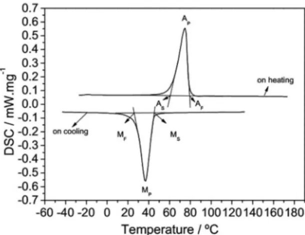
Figure 2 shows the transformation behavior of the solution treated 2.080 mm in diameter wire. The direct and reverse martensitic transformations occur at just one step,
B19' (martensite) ↔ B2 (austenite). The DSC results are
summarized in Table 1. The wires are in the martensitic
state at room temperature (25 °C), in a mixed state (M +
A) at 70 and 75 °C, and in the austenitic state at 80 and 110 °C, which is corroborated by tensile and wire drawing tests.
Figure 3 shows the true stress-strain curves of solution treated 2.080 mm in diameter wire, tensile tested at 25, 70,
75, 80, and 110 °C. At 25 and 70 °C, the wires exhibit a stress plateau (critical stress) after the first yield stress and
present the characteristic SMA pseudoplastic deformation16.
At 25 °C, the wire is in the martensitic state, according to
Table 1, and show two well-defined yield stresses, one at ~160 MPa and the other at ~600 MPa. The first yield stress
corresponds to the pseudoplastic deformation (beginning
of detwining or reorientation of pre-existing martensite
Table 1. Direct and reverse martensitic transformation temperatures of the solution treated 2.080 mm in diameter wire.
MS (°C) MP (°C) MF (°C) AS (°C) AP (°C) AF (°C) MD* (ºC)
46.0 36.7 26.0 60.6 74.8 79.0 Between 80 and 110
* The MD value was estimated by the shape of curves from tensile test presented in Figure 3.
Figure 2. DSC measurements of transformation behavior of the
solution treated 2.080 mm in diameter wire.
(DTM). At 70 °C, the wire has a mixed crystallographic state (M + A), where the temperature is between AS (60.6
°C) and AF (79.0 °C). Although the tensile curve profile at
70 °C was similar to the one at 25 °C, the first yield stress is 25% higher (~200MPa) and the second yield stress is 10% lower (~540 MPa) than that in the 25 °C test. The first
yield stress is related to the beginning of the detwinning of thermal martensite and the beginning of the stress-induced martensite (SIM). The second yield stress is the beginning
of plastic deformation of the martensite (DTM + SIM), as
before at 25 °C. At 75 and 80 °C, the characteristic double
yield stress almost disappears taking into account that AF is
79.0 °C. In this case, the yield stress is the stress necessary to stress induce the martensite which is higher, the higher the tensile testing temperature, indicating that the austenite is a stable phase10,16. At 110 °C, the tensile behavior tends to be
similar to a conventional metallic material presenting only one yield stress, and no SIM is seen, which indicates that the wire should be above MD (MD is the highest temperature to SIM2,13). Still from Figure 3, disregarding the type of
deformation, the specific NiTi mechanical behavior induces
the following conclusions: the 25 °C curve illustrates that up to about 0.07 mm2.mm-2 strain, the wire behaves like
a soft metallic material with low yield stress (e. g. ~160
MPa at 25 °C) and low work-hardening. For higher strains, the wire behaves like a hard-metallic material with a high yield stress of about 600 MPa, which surpasses mechanical
resistance of the higher testing temperature and has higher
work-hardening.
The upper plateau strength (UPS), also known as critical
stress, is the stress at 3% of strain during loading test13. The
Figure 3. True stress-strain curves of solution treated 2.080 mm
wire tensile tested at 25, 70, 75, 80, and 110 °C.
literature shows that the UPS, of a near equiatomic NiTi
shape memory alloy, increases monotonically from ~140
to ~325 MPa when the test temperature increases from AS
to AF11. As can be seen in Figure 3, the UPS increased from
213 to 331 MPa, when the temperature increased from 70ºC
(close to AS) to 80ºC (close to AF). It is expected that this
mechanical behavior will influence the wire drawing process.
The above results are very important in terms of practical wire drawing insofar as the area reduction involved is usually higher than 0.10 mm2.mm-2. For a complete understanding
of wire drawing work, the uniform drawing work and total drawing work should be analyzed.
Considering that the area under the true stress-strain curve
corresponds to uniform work, it is expected that the wire drawing will be influenced by this non-conventional mechanical
behavior originated by pseudoplastic deformation. As two
kinds of deformations exist, the plastic and the pseudoplastic, the uniform work must be distinguished by naming one as "plastic uniform work", and other as "pseudoplastic uniform work", and the total uniform work or just the uniform work is the sum of them. Figure 4 shows the uniform work, calculated
from the true stress-strain curves of Figure 3, limited to the left of vertical lines at 0.075, 0.15, and 0.24 mm.mm-1 of true
strain that correspond to 0.07, 0.14, and 0.21 mm2.mm-2 of
area reduction in wire drawing, as a function of the tensile testing temperature. Comparing the three deformations shows
that the pseudoplastic uniform work, for a 0.07 mm2.mm-2
jumped to ~25 J.m-3, indicating that the plastic uniform work
is higher than that of the pseudoplastic uniform work. The uniform drawing work for a 0.14 mm2.mm-2 area reduction,
also presents similar behavior as for 0.07 mm2.mm-2, but
the positive steepness as the temperature increases is lower, noting that, in this case, the plastic deformation of DTM and SIM is occurring due to higher strain. The values are respectively ~45 J.m-3 at 25 °C and ~65 J.m-3 at 110 °C. For a
0.21 mm2.mm-2 area reduction, the uniform work is constant
up to 70 °C and then decreases for deformation at a higher temperature of 75 and 80 °C, then slightly increases at 110
°C, with the extremes values of ~105 J.m-3. The uniform
work, in this case, corresponds to the conventional plastic
deformation of the austenite phase. Figure 5 presents the total
work as a function of temperature for 0.07, 0.14 and 0.21
mm2.mm-2 area reductions. Remember that the total work
corresponds to the sum of uniform work, redundant work, and friction work; the last two terms do not contribute to effective deformation and should be minimized.
As shown in Figure 5, for a 0.07 mm2.mm-2 area reduction,
the total work is almost constant up to 70 °C (~100 J.m-3),
and then increases steeply from 70 to 80 °C and then to ~175 J.m-3 at 110 °C, that is, a ~75% increase closely following
the behavior of uniform work. The pseudoplastic uniform work at 25 °C is about 10% and the plastic uniform work is about 14% at 110 °C of total work. Therefore, for a low area reduction, the efficiency of drawing work (i.e. the ratio of uniform work to total work) is low and most of the energy is spent as friction work, as the redundant work is supposed to be very low due to the low geometric factor, Δ, of 212. For
0.14 mm2.mm-2 area reduction, the total work is practically
constant at ~250 J.m-3, and in this case, the uniform work
corresponds to 20% at 25 °C and 26% at 110 °C of the total
work, improving the drawing efficiency compared to 0.07
mm2.mm-2 area reduction. The highest degree of deformation,
0.21 mm2.mm-2 of area reduction, present the best results
in terms of total work, and it steeply decreases from ~380
J.m-3 at 25 °C to ~310 J.m-3 at 110 °C. The uniform work
corresponded to 27% and 50% of total work in those extremes. The above analyses took into account only the wire drawing temperature and area reduction per drawing pass keeping constant other die parameters such as Δ factor, drawing angle,
and lubricant. The manipulation of those parameters should
optimize the uniform work, minimizing the redundant work and the frictional work.
Figure 4. The uniform work calculated from the tensile testing of
solution treated 2.080 mm diameter wire as a function of temperature for 0.07, 0.14, and 0.21 mm2.mm-2 area reduction.
Figure 5. The total drawing work as a function of drawing temperature
for the solution treated 2.080 mm diameter wire, drawn in a single pass of 0.07, 0.14, and 0.21 mm2.mm-2 area reduction.
Figure 6. True stress-strain curves at 25 °C for the wire drawn at
25 and 110 °C with 0.21 mm2.mm-2 area reduction.
Figure 6 shows the results of the tensile test at 25 °C for the wires drawn at 25 and 110 °C with 0.21 mm2.mm-2
area reduction. This resulted in two drawing products: the
work-hardened martensite wire drawn at 25 °C and the work-hardened austenite wire drawn at 110 °C, above MD,
therefore no SIM existed. The wire drawn at 25 °C presented higher tensile stress than that at 110 °C. This would reflect in higher uniform work if a new drawing step is to be carried
Summarizing, the above results indicate that, for wire drawing with low area reduction, it is much easier to wire draw at low temperature where the martensite state prevails, which corroborates with Wu14. However, for higher area
reduction, as is normal of wire drawing, it is more efficient
to wire draw in high temperatures, preferentially above MD,
where the total drawing work and tensile stress of the product are lower. Nevertheless, as shown in earlier work17, even for
wire drawing at low temperature (25ºC), which is usually done in industrial scale, area reduction as high as 56% with 15% area reduction per pass can be obtained.
4. Conclusion
The NiTi wire presented a well-known four-step tensile profile at temperatures below AS: an elastic deformation of the
previous phase; a transformation stress plateau after the first
yield stress; an elastic deformation of the new transformed
phase; and finally, the second yield stress corresponding to
the beginning of conventional plastic deformation. Those characteristics disappear as the temperature approaches AF, and above MD, the mechanical behavior is similar to a conventional material.
The results of uniform work and total work indicate that the efficiency of wire drawing increases as the area reduction
and drawing temperature increases. The contributions of
uniform work for 0.07 mm2.mm-2 area reduction are about
10 and 14% of total work, respectively, for 25 and 110 °C,
while for 0.21 mm2.mm-2 area reduction are 27 and 50% of
total work for the same range of temperature.
Two drawing products can be obtained varying the
drawing temperature: work-hardened martensite (below
MD) and work-hardened austenite (above MD).
It is recommended that the wire be drawn at an elevated temperature associated with high area reduction in order to
increase the ratio between uniform work and total work, taking into account the desired properties associated to reasonable workability.
Compared to conventional wire drawing, pseudoplastic
uniform work should be considered on wire drawing shape memory alloys to distinguish from the plastic uniform work.
Studies are underway to incorporate the pseudoplastic uniform
work into the total drawing work on wire drawing SMAs. The results from the wires with final diameters of about 2 mm can be extrapolated for larger and smaller diameters provided that a specific included die angle 2α can be
manufactured.
5. Acknowledgements
The authors wish to thank FAPESP, CAPES, CNPq, FINEP, Multialloy Metais Especiais Ltda, and Villares Metals
SA for supporting the ITASMART (ITA Shape Memory Alloy Research and Technology) Group.
6. References
1. Otsuka K, Wayman CM. Shape Memory Materials. 1st ed.
Cambridge University Press; 1998. 300 p.
2. Miyazaki S, Otsuka K. Development of Shape Memory Alloys. ISIJ International. 1989;29(5):353-377.
3. Otsuka K, Ren X. Physical metallurgy of Ti-Ni-based shape
memory alloys. Progress in Materials Science. 2005;50(5):511-678.
4. Kohl M, Just E, Pfleging W, Miyazaki S. SMA microgripper
with integrated antagonism. Sensors Actuators A: Physical. 2000;83(1-3):208-213.
5. Miyazaki S, Kohl M. Recent Development in TiNi-based Shape
Memory Alloys. Smart Structures and Materials. 1998; p. 2-13.
6. Fernandes DJ, Elias CN, Vidal R, Mendes AM. Mechanical Performance of Nickel-titanium Archwires. Materials Research. 2015;18(6):1264-1277.
7. Matheus TCU, Lopes HP, Albuquerque DS, Elias CN, Carmo
AMR, Otubo J, et al. The fracture evaluation of NiTi SMA
endodontics files. Materials Research. 2007;10(4):395-398.
8. Otubo J, Rigo OD, Moura Neto C, Kaufman MJ, Mei PR. Low
carbon content NiTi shape memory alloy produced by electron beam melting. Materials Research. 2004;7(2):263-267.
9. Soul H, Yawny A, Lovey FC, Torra V. Thermal effects in a
mechanical model for pseudoelastic behavior of NiTi wires.
Materials Research. 2007;10(4):387-394.
10. Kumar PK, Lagoudas DC. Introduction to Shape Memory Alloys. In: Lagoudas DC, ed. Shape Memory Alloys. New
York: Springer; 2008. p. 1-51.
11. Liu Y, Galvin SP. Criteria for pseudoelasticity in near-equiatomic
NiTi shape memory alloys. Acta Materialia. 1997;45(11):4431-4439.
12. Wright R. Wire Technology - Process Engineering and Metallurgy. Oxford: Butterworth-Heinemann; 2011. p. 25-26.
13. ASTM International. ASTM F2005-05(2010) - Standard Terminology for Nickel-Titanium Shape Memory Alloys. West
Conshohocken: ASTM International; 2010.
14. Wu SK, Lin HC, Yen YC. A study on the wire drawing of TiNi
shape memory alloys. Materials Science and Engineering. 1996;215(1-2):113-119.
15. ASTM International. ASTM F2004-16 - Standard Test Method for Transformation Temperature of Nickel-Titanium Alloys by Thermal Analysis. West Conshohocken: ASTM International;
2016.
16. Pelton AR, Dicello J, Miyazaki S. Optimisation of processing
and properties of medical grade Nitinol wire. Minimally Invasive Therapy & Allied Technologies. 2009;9(1):107-118.
17. Kabayama LK, Rigo OD, Otubo J. Influence of Thermomechanical Processing on the Martensitic Transformation Temperatures of