Relationship Between Aluminum-Rich/Intermetallic Phases and Microhardness of a
Horizontally Solidified AlSiMgFe Alloy
Carolina Rizziolli Barbosaa, José Otávio Monteiro de Limaa, Gabriel Mendes Hirayama Machadoa, Hugo André Magalhães de Azevedoa, Fernando Sousa Rochaa, André Santos Barrosb,
Otávio Fernandes Lima da Rochaa,b*
Received: May 23, 2018; Revised: September 02, 2018; Accepted: October 03, 2018
An experimental study with an A356-AlSiMgFe alloy was developed to evaluate the microhardness
performance in the microstructure resulting of an unsteady-state horizontal solidification process. The Al-7wt%Si-0.3wt%Mg-0.15wt%Fe alloy was elaborated and directionally solidified in a water-cooled horizontal solidification device. In order to experimentally determine the cooling and growth rates (VL
and TR, respectively), a thermal analysis was also conducted during solidification. Microstructural characterization by optical microscopy, SEM/EDS elemental mapping and microanalysis of the
punctual EDS compositions allowed to observe the presence of an Al-rich dendritic phase (Al(α)) with interdendritic phases second composed of an eutectic mixture: Al(α-eutectic) + Si + Al8Mg3FeSi6(π) + Mg2Si(θ). Furthermore, the dendritic microstructure was characterized by measuring the secondary
dendritic spacings (λ2) along the horizontally solidified ingot. Higher HV values were observed within
the eutectic mixture.
Keywords: Solidification process, Unsteady-state heat flow, Intermetallic phases, Microhardness, AlSiMg alloys.
*
e-mail:[email protected]
1. Introduction
It is known that aluminum-based multicomponent alloys
due to their high strength/weight ratio have been considered as one of the most promising materials for application in the automotive and aerospace industries as well as in those referring to electrical and naval engineering1-32. Depending
on the product, these alloys can be classified as plastic deformation and/or casting alloys. Among these alloys,
especially those for casting, are highlighted those containing
silicon as the main alloying element. In Al-Si alloys, the addition of some alloying elements (Mg and Cu, as example)
increases the strength by solid solution or precipitation hardening32. This hardening occurs through the formation
of barriers that hinder the movement of dislocations. It is highlighted that the Al-(5 to 12)wt%Si casting alloys with addition of magnesium ranging from 0.2 to 0.5 wt% allows
the hardening of the matrix by precipitation of second phases, with emphasis to the Mg2Si phase, after solution and artificial aging heat treatments29-32.
It is important to emphasize that the mechanical properties
of as-cast products depend on grain size, dendritic, lamellar
or fibrous spacing, heterogeneities of chemical composition,
size, shape and distribution of inclusions, formed porosity,
etc., whose characteristics are controlled and improved by refining the microstructure11-16. It is known that the
dendritic morphology is the microstructure predominantly observed in castings, whose characterization consists of the
quantification of a structural parameter known as interdendritic
spacing, which is obtained by measuring of the primary
(λ1), secondary (λ2) and tertiary (λ3) dendrite arm spacings.
These parameters are used to determine the effects of the solidification conditions, notably by the thermal parameters among which the growth rate (VL) and cooling rate (TR). It
is a consensus from the works reported in the literature 2-6,8-40 that the mathematical expressions that characterize the
dependence of the dendritic spacings with the solidification
thermal parameters are described by the following general
formula λ123=Constant.(VL, TR)
a, where the constant and exponent values depend on the types of alloys and the growth
direction (vertical/horizontal) of the solidification process. In the case of unsteady-state directionally solidified binary alloys,
both theoretical and experimental mathematical equations
that correlate λ2 as a function of VL and TR, the proposed
exponents are -2/3 and -1/3, respectively. It is highlighted the mathematical model of Bouchard-Kirkaldy16 that predicts the
growth of λ2 as a function of VL is given by λ2 α VL
-2/3, whose
exponent (-2/3) has been validated by several experimental investigations on unsteady-state directional solidification
of aluminum-based binary and multicomponent alloys, for both horizontal and vertical directions2,16,17,23,25-28,38,39. Among
the works on transient solidification, it is emphasized those
aInstituto Federal de Educação, Ciência e Teccnologia do Pará - IFPA, 66093-020, Belém, PA, Brasil
bFaculdade de Engenharia Mecânica, Universidade Federal do Pará - UFPA, 66075-110, Belém, PA,
reported for binary Al-Si2,38,39 and multicomponent Al-Si-(Cu and Mg)23,25-28,30 alloys.
With regard to the investigations on upward
steady-state solidification, Kaya et al.5,6 and Çadirli41 have reported
different exponents values for binary Al-Si and Al-Cu alloys, respectively. The following mathematical relations given by λ2 α VL
-0.47 and λ
2 α VL
-(0.27 to 0.46) have been proposed by
Kaya et al.6 for Al-3wt% Si and Çadirli41 alloys for Al-XCu
(X=3, 6, 15, 34 and 33wt.%Cu) alloys, respectively. For
multicomponent alloys, Rappaz-Boettinger 22 have reported
a mathematical model that correlates λ2 with a function
of the local solidification time (tSL) given by the general
formula λ2 = 5.5.[M (tSL)]
1/3, which has been validated by
works elaborated by the own authors22 and, more recently,
by our investigations with horizontally solidified Al-Si-Cu
alloys25,27,28.
Although the literature has presented in the last decades a large number of studies on the structural evolution of casting alloys, due to the number of operational and thermal parameters
involved during the solidification, several aspects of physical
nature related to the formation of the macrostructure and microstructure of products obtained by casting still need
to be effectively understood, especially with respect to the solidification growth direction and, consequently, the effect of the gravity that acts during the process. It is evidenced from the literature that most studies on directional solidification
consider the upward direction, where the direction of the gravity is parallel to that of heat extraction, but contrary
to the advance of solidification, promoting better thermal
stability to the process 2,5,6,8,9,17,18,23,25-27,31,36. On the other hand,
in horizontal solidification, the gravity is perpendicular to
the heat flow and solidification advance direction and, in
this case, thermal instabilities are always present due to
the effects of thermal and solutal convections3,4,21,25,28,37. In a recent study25, the Al-4wt%Si-6wt%Si alloy was solidified
upwards and horizontally and the effect of the gravity has
been discussed, where microanalyses by EDS compositons
have shown that the dendritic microstructure is more refined,
and that the results of the microssegration demonstrated that
in upward solidification the Si is more confined between the interdendritic branches reducing the λ1 and λ2 values.
The composition of Al-Si alloys is determined by the amount of iron impurity present. It is emphasized that iron (Fe) levels generally vary from 0.04% (best primary metal) to 0.50% (secondary metal), with typical primary levels in the 0.1 to 0.2% range30,32. In this sense, the formation of
Fe-intermetallic phases during the solidification of Al-Si alloys is inevitable, as can be seen by the solidification paths of Al7Si0.15Fe and Al7Si0.3Mg0.15Fe alloys shown in Figure 1. It is observed that for Al-Si hypoeutectic alloys (Figure 1a) the microstructure is predicted to consist of a primary phase (Alα) and by an eutectic mixture Al(α-eutectic) + Si + Fe intermetallic located between the Alα phases. On the other hand, the theoretical prediction of the microstructure for
the alloy for the Al7Si0.3Mg0.15Fe alloy consists of a Al-rich primary phase (Al(α)) and an eutectic mixture resulting from complex transformations of secondary phases, containing the eutectic phase Al(α) and intermetallic compounds,
i.e: Al (α-eutectic) + Si + Al8Mg3FeSi6 (π) + Mg2Si (θ) + Fe
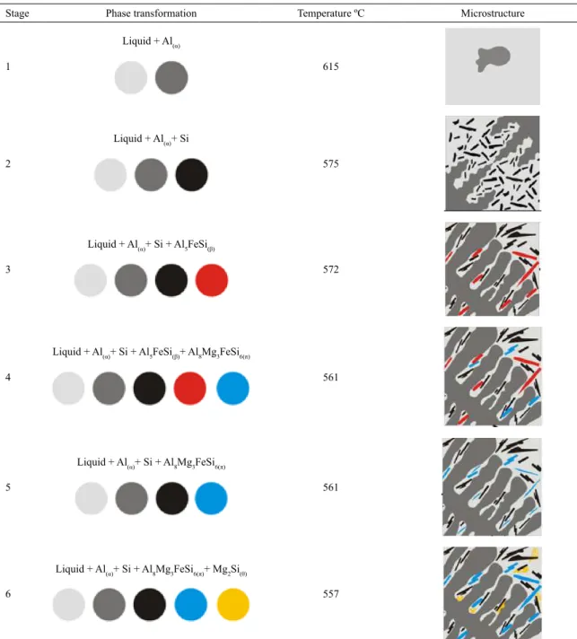
intermetallic. Figure 2 shows, for the Al7Si0.3Mg0.15Fe
alloy, a prediction illustration of the microstructural evolution
with the respective formation start temperatures of each phase
shown by the solidification path (Figure 1b).
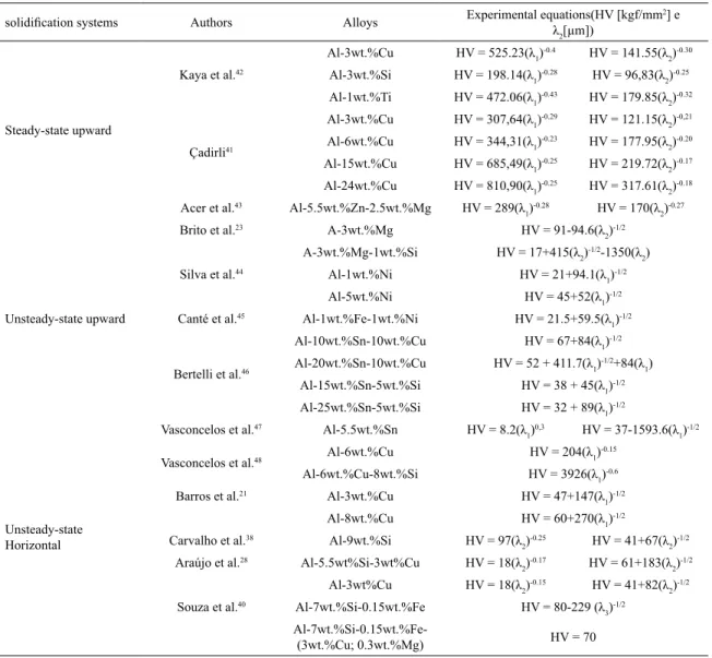
The dependence of the microhardness (HV) on the
microstructure in Al-based binary and multicomponent alloys
has been investigated for several directional solidification
systems23,28,38,41-48 and the results obtained in these studies
have shown that power and Hall-Petch types experimental equations may characterize the variation of HV with λ1, λ2
and λ3, of which the alloys containing the Si as the major
alloying element with Cu/Mg/Sn addition are highlighted. This can be seen in Table 1.
Chen et al.30 have proposed a study on the interconnection
between solidification microstructures with T6 heat treatment, whose results showed that more refined dendritic microstructures, i.e., smaller secondary dendritic spacings inherited greater yield strength (σYS) and ultimate tensile strength (σUTS) after
heat treatment. These authors have proposed to the literature for the as-cast Al-7wt%Si-0.3wt%Mg alloy the following mathematical equations: σYS = 0.0041(λ2)
2+0.118(λ
2) + 111.1
and σUTS = 0.029(λ2) 2+1.72(λ
2) + 155.8.
In Al-Si cast alloys the Si particles have a plate (or
lamellar) type morphology, which acts as initiators for
crack propagation and has a negative influence on ductility.
Stage Phase transformation Temperature ºC Microstructure
1
Liquid + Al(α)
615
2
Liquid + Al(α)+ Si
575
3
Liquid + Al(α)+ Si + Al5FeSi(β)
572
4
Liquid + Al(α)+ Si + Al5FeSi(β)+ Al8Mg3FeSi6(π)
561
5
Liquid + Al(α)+ Si + Al8Mg3FeSi6(π)
561
6
Liquid + Al(α)+ Si + Al8Mg3FeSi6(π)+ Mg2Si(θ)
557
This can be improved by changing the morphology of the Si from lamellar to fibrous or spheroidal, imposing, for example, high cooling rates (TR) during solidification, or
by the addition of a chemical modifier or by heat treatment, or by a combination of such processes. The microstructural
characteristics and properties corresponded presented by
the multicomponent Al-7wt%Si-0.3wt%Mg-0.15wt%Fe alloy, very well designed during the solidification and heat
treatment processes, allow it to be one of the most applied aluminum-based nonferrous metal alloys in the aerospace and automotive industries30,32.
As can be seen from Table 1, HV dependence on the
microstructure has been evaluated as a function of the dendritic spacing values, however, there is still a gap in the literature
about a study of the effects on microhardness of primary and secondary phases that are form during the solidification
path of Al-based ternary alloys, in particular on horizontal
solidification of AlSiMgFe alloys. Thus, the goal of this
paper is to analyze the relationship between aluminum-rich/
intermetallic phases and microhardness of the horizontally
solidified Al-7wt.%Si-0.3wt.%Mg-(0.15wt.%Fe) alloy. In
addition, the microstructural evolution in aluminum alloys has been evaluated in the majority for binary alloys and, in this sense, there is still a great vacancy in the literature
on studies of directional solidification, especially in the horizontal direction.
2. Experimental Procedure
The Al-7wt%-Si-0.3wt%Mg-0.15wt%Fe alloy was elaborated and directionally solidified in a water-cooled horizontal solidification device. Figure 3 shows a schematic of the device used to perform the horizontal solidification of the investigated alloy. It has been detailed and recently
published 28 and it was designed for the heat extraction process to be conducted only by a cooled mold plate, located on one of the sides of a stainless steel rectangular mold, which has
the following dimensions: thickness of 3 mm, a length of
Table 1. HV dependence on λ1, λ2 and λ3 reported in the literature for Al-based alloys.
solidification systems Authors Alloys Experimental equations(HV [kgf/mm
2] e λ2[µm])
Steady-state upward
Kaya et al.42
Al-3wt.%Cu HV = 525.23(λ1)
-0.4 HV = 141.55(λ
2)
-0.30
Al-3wt.%Si HV = 198.14(λ1)
-0.28 HV = 96,83(λ
2)
-0.25
Al-1wt.%Ti HV = 472.06(λ1)
-0.43 HV = 179.85(λ
2)
-0.32
Çadirli41
Al-3wt.%Cu HV = 307,64(λ1)
-0.29 HV = 121.15(λ
2) -0,21
Al-6wt.%Cu HV = 344,31(λ1)
-0.23 HV = 177.95(λ
2)
-0.20
Al-15wt.%Cu HV = 685,49(λ1)
-0.25 HV = 219.72(λ
2)
-0.17
Al-24wt.%Cu HV = 810,90(λ1)
-0.25 HV = 317.61(λ
2)
-0.18
Acer et al.43 Al-5.5wt.%Zn-2.5wt.%Mg HV = 289(λ
1)
-0.28 HV = 170(λ
2)
-0.27
Unsteady-state upward
Brito et al.23 A-3wt.%Mg HV = 91-94.6(λ
2) -1/2
A-3wt.%Mg-1wt.%Si HV = 17+415(λ2)
-1/2-1350(λ 2)
Silva et al.44 Al-1wt.%Ni HV = 21+94.1(λ
1) -1/2
Al-5wt.%Ni HV = 45+52(λ1)
-1/2
Canté et al.45 Al-1wt.%Fe-1wt.%Ni HV = 21.5+59.5(λ
1) -1/2
Bertelli et al.46
Al-10wt.%Sn-10wt.%Cu HV = 67+84(λ1)
-1/2
Al-20wt.%Sn-10wt.%Cu HV = 52 + 411.7(λ1)
-1/2+84(λ 1)
Al-15wt.%Sn-5wt.%Si HV = 38 + 45(λ1)
-1/2
Al-25wt.%Sn-5wt.%Si HV = 32 + 89(λ1)
-1/2
Unsteady-state Horizontal
Vasconcelos et al.47 Al-5.5wt.%Sn HV = 8.2(λ
1)
0,3 HV = 37-1593.6(λ
1) -1/2
Vasconcelos et al.48 Al-6wt.%Cu HV = 204(λ1)
-0.15
Al-6wt.%Cu-8wt.%Si HV = 3926(λ1)
-0.6
Barros et al.21 Al-3wt.%Cu HV = 47+147(λ
1) -1/2
Al-8wt.%Cu HV = 60+270(λ1)
-1/2
Carvalho et al.38 Al-9wt.%Si HV = 97(λ
2)
-0.25 HV = 41+67(λ
2) -1/2
Araújo et al.28 Al-5.5wt%Si-3wt%Cu HV = 18(λ
2)
-0.17 HV = 61+183(λ
2) -1/2
Al-3wt%Cu HV = 18(λ2)
-0.15 HV = 41+82(λ
2) -1/2
Souza et al.40 Al-7wt.%Si-0.15wt.%Fe HV = 80-229 (λ
3) -1/2
Figure 3. Scheme of the horizontal solidification apparatus used in this investigation.
Figure 4. Experimental cooling curves for six positions of the horizontally solidified Al-7wt%Si-0.3wt%Mg alloy. TSh, TL and TE, are the superheat, liquidus and eutectic temperatures of the studied alloy.
150 mm, a height of 60 mm, and a width of 60 mm. It can be noted in Figure 3, within the dashed line area.
A thermal mapping was performed during the
solidification process by a set of six thermocouples inserted
in the liquid metal, which were positioned from the cooled
mold. Figure 4 shows the cooling curves obtained, for each
thermocouple, which were used to determine experimentally
the solidification kinetic. It has been represented by a power-type mathematical expression given by P = Constant.(t)n,
where “P” is the liquidus isotherm displacement and “t” is the
time corresponding to the passage of this isotherm for each thermocouple, and the derivative of this equation allowed
to obtain the growth rate (VL), i.e., VL = d[Constant.(t) n]/dt.
The cooling rate has been determined by the derivative of each curve [T = f(t)] obtained experimentally, i.e., TR = dT/dt for "t" equal to the time of passage of the liquidus isotherm
for each thermocouple. This methodology has been detailed
in several of our articles3,4,21,25-28.
In order to reveal the macrostructure and microstructure,
the resulting ingot was subjected to traditional metallography
techniques, i.e, it was mechanically polished with abrasive
papers and subsequently etched with a solution 70 ml of
H2O, 10 ml of HCl, 15 ml of HNO3 and 5 ml of HF ~ 30s for
macrograph examination, and selected longitudinal (parallel to the growth direction) sections of the directionally solidified
samples at 6, 10, 15, 20, 30, 50, 80 and 100 mm from the cooled interface were electropolished and etched with an
solution of 5% of NaOH in water ~ 10s for micrograph examination. It was carried out to characterize and quantify the secondary dendrite arm spacing (λ2).
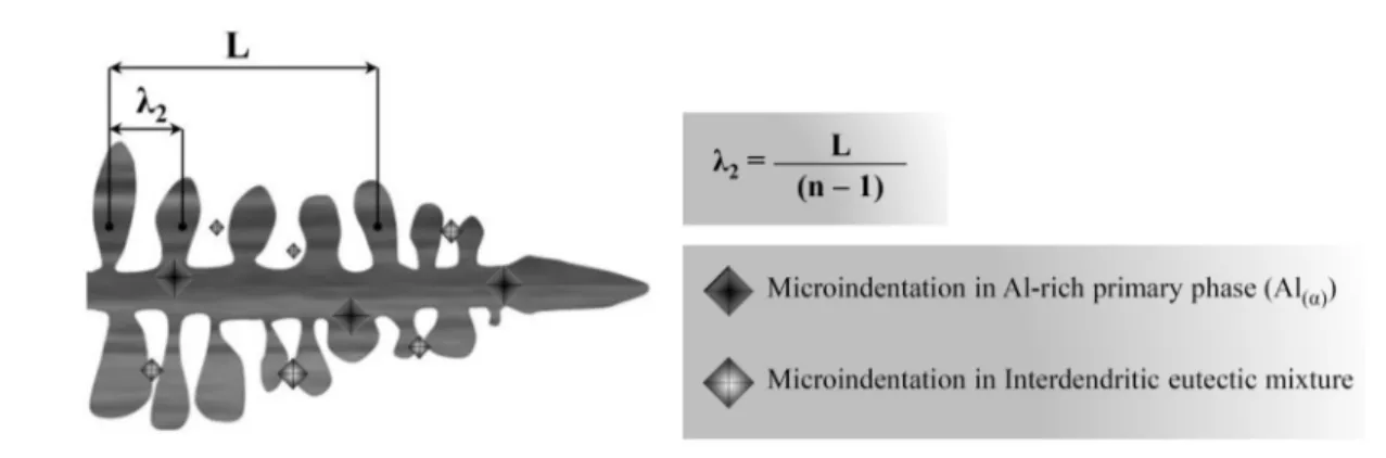
The mechanical strength of the studied alloy was evaluated by microhardness measurement. It has been carried out in
the center of the dendrite, aluminum-rich phase, as well as in the eutectic mixture located in the interdendritic region
of the Al-7wt%Si-0.3wt%Mg-0.15wt%Fe alloy. Figure 5
shows a representative scheme of the methodology used in
this work to obtain the λ2 and HV values. It is emphasized that at least 10 and 20 measurements were obtained for
HV (in each region) and λ2, respectively. In the case of microhardness the quantity of measurements occurred in
Figure 5. Measurement technique of the (2 and HV values.
A scanning electron microscope (SEM TESCAM, VEGA LMU) coupled to an energy dispersion spectrum (EDS X-MAX 20, Oxford) was used during microstructural
characterization, and the microhardness measurements were
carried out using by Shimadzu HMV-2 model hardness
measuring test device using a 50 g load and a dwell time
of 10 seconds.
3. Results and Discussions
Figure 6a shows the revealed macrography of the ingot of the investigated alloy and the microstructural evolution
with the growth of the horizontal solidification. The dendritic
morphology has been characterized along the length of
the ingot as the microstructure of the primary phase (Alα). The dendritic Alα microstructure has been characterized by
secondary dendritic spacing, and the λ2 dependence on VL and
TR values has been evaluated by power-type mathematical
expressions given by the general formulas λ2 = Constant.
(VL) -2/3 e λ
2 = Constant.(TR)
-1/3, as shown in Figure 6b.
The values of the exponents of -2/3 and -1/3 are exactly equal to the values proposed by the Bouchard-Kirkaldy
16 and Rappaz-Boettinger 22 mathematical models, which
characterize the λ2 variation with the growth rate and local
solidification time (tSL) through the following mathematical
relations λ2 α VL -2/3 and λ
2 α tSL
1/3, respectively. It is known
that the local solidification time is the time corresponding to
the passage of the solidus and liquidus isotherms (TE and TL shown in Figure 4, respectively) by a certain position in the casting 25, and the t
SL has been reported in the literature 7,25-28 to be determined by the following analytical expression tSL=ΔT/TR (ΔT=TL-TE).
Is obvious that lower VL and TR values have been observed for positions further away from the cooled interface, due to an increasing formation of the solid, which imposes a thermal resistance to the heat extraction by conduction and,
as consequence, an increasing profile of λ2 has been observed
with the advance of horizontal solidification. This is clearly seen by the three micrographs (6, 40 and 90 mm) shown
in the upper part of the macrograph (Figure 6a) the coarser microstructure from the cooled interface.
Figure 7 shows SEM micrographs with EDS/mapping microanalysis for two longitudinal samples in the
as-solidified ingot from the cooled interface. Microanalysis
has been performed by mapping elements to a linear length
through several secondary braches. It is observed, for both
cases, that the line intercepts the primary and interdendritic
phases. Obviously, this is evidenced higher spectra peaks for
the Si, Mg and Fe elements within the intedendritic region which have allowed to form the eutectic mixture consisting of Al (α-eutectic) + Si + Al8Mg3FeSi6 (π) + Mg2Si (θ), as seen
theoretically by Figures 1 and 2.
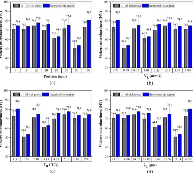
In this work, the HV dependence on the thermal and structural parameters of the Al-7wt.%Si-0.3wt.%Mg alloy has been evaluated by measuring of HV in the phases of the Al-rich (Alα) and interdendritic [Al (α-eutectic) + Si + Al8Mg3FeSi6 (π) + Mg2Si (θ)] regions. Figure 8 shows the
experimental results of HV = f (P, VL, TR and λ2), where
P is liquidus isotherm position. It is observed that higher HV values were obtained in the interdendritic regions, in which Si + π + θ particles of high hardness are present. Vasconcelos et al.48, Araújo et al.28 and Souza et al.40 have
found higher HV values for Al-Si multicomponent alloys with addition of Cu and Mg and the authors have attributed to the presence of intermetallic phases (Al2Cu and Mg2Si) of
high hardness in the interdendritic region of the as-solidified samples. In contrast to the procedure adopted in the present study, these authors did not perform HV measurements in the Al-rich and eutectic phases, the HV values reported by
them were the means of 20 measurements obtained directly
in the casting samples.
Figure 9 presents, for one of the analyzed samples
(P = 20 mm), the effect of Al-rich (dendritic primary phase) and interdendritic (eutectic mixture) phases on the formation
of microindentation caused during the application of the load
for HV measurement. It is noted that the HV microindentation
is smaller in the region of greater hardness, in which the
Figure 6. Microstructural evolution and correlation with the solidification thermal parameters: (a) Typical solidification macroestructure and microstructure and λ2 = f (P); (b) λ2 = f (VL and TR).
Figure 8. HV variation with a function of: (a) ingot position - P, (b) growth rate - VL, (c) cooling rate - TR and (d) secondary dendritic spacing λ2.
present. Barros et al.21 developed a study with horizontally
solidified Al-XCu (X = 3 and 8 wt%) alloys, presenting as results a comparison between the impressions of the HV
microindentations observed in the Al(α) dendritic primary and Al(α-eutectic) + Al2Cu interdendritic phases, which also showed
smaller microindentations in the interdendritic region. In order to analyze the phases present during the solidification process of the investigated alloy, SEM/EDS
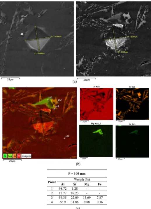
mapping and microanalysis of the EDS compositions have been elaborated in the sample positioned at 100 mm of the refrigerated interface, position of the liquidus isotherm
where higher HV values were found, and the results are shown in Figure 10. It is seen in Figure 10a that the L1
and L2 dimensions of the microindentation diagonals in
the aluminum-rich region are higher. The mean values obtained [(L1 + L2)/2] were 34.96 and 31.34 in the Alα and interdendritic Al (α-eutectic) + Si + Al8Mg3FeSi6 (π) + Mg2Si (θ)
regions, respectively, representing an approximate difference
of 11%. This percentage difference has also been evidenced between the HV values (72.8 and 80.7) for the same position (100mm), as observed in Figure 8a.
It was possible to verify in Figures 8a and 9 that the maximum HV value was obtained at position 100 mm, in which, although this position presents the lowest TR and
higher λ2 values (see Figures 8c and 8d), the Si particles are in larger size, in lamellar form and present high hardness,
as can be seen in Figure 11. It is also evidenced by SEM micrographs presented at the top of Figure 11 the influence of higher TR values in the formation of Si particles with fine
and fibrous morphology. In a recent paper, Costa et al.26 have
evaluated the effects of TR on the size and morphology of Si
particles in the Al-5.5wt%Si-3wt%Cu alloy, solidified in the
upward direction and subjected to a precipitation hardening
Figure 9. Schematic representation of the effect of the phases on the HV microindentation at position equal to 20 mm from the refrigerated interface.
Figure 10. Representation of microindentation by scanning electron microscopy (SEM) at position equal to 100 mm: (a) SEM micrograph, (b) elemental mapping, (c) ponctual EDS analysis.
fibrous form and this has potentiated the its spheroidization after the solution heat treatment.
4. Conclusions
The major conclusions can be drawn from the present
investigation:
1. SEM / EDS mapping combined with microanalysis of the EDS compositions showed that the as-cast
Figure 11. Effect of the cooling rate on the Si morphology and HV values.
mixture composed of the Al(α-eutectic) + Si + Al8Mg3FeSi6(π) + Mg2Si(θ) phases.
2. The dendritic morphology was the microstructure of the primary phase [Al(α)] observed along the length
of the ingot of the investigated alloy. It has been quantified by the secondary dendrite arms spacings
and the following mathematical expressions have
characterized the λ2 dependence on the VL and TR
values: λ2=20(VL) -2/3 and λ
2=28.5(TR) -1/3.
3. Obviously, higher HV values were observed in the
interdendritic region, where high hardness phases are
present. However, this work presents as novelty to the literature, for the investigated alloy and solidified
under assumed conditions, experimental values of
HV in the Al-rich and eutectic phases.
4. Finer and fibrous Si particles have been verified
in samples located closer to the cooled base of the
horizontal solidification device, in which the TR
and λ2 values are higher and smaller, respectively.
5. It was observed that the maximum HV values
were found at the position equal to 100 mm from the cooled interface, where the Si particles in the plate-type morphology of larger sizes and higher
harder are present.
5. Acknowledgments
6. References
1. Steinbach S, Ratke L. The Influence of Fluid Flow on the Microstructure of Directionally Solidified AlSi-Base Alloys. Metallurgical and Materials Transactions A. 2007;38(7):1388-1394.
2. Peres MD, Siqueira CA, Garcia A. Macrostructural and microstructural development in Al-Si alloys directionally solidified under unsteady-state conditions. Journal of Alloys and Compounds. 2004;381(1-2):168-181.
3. Carvalho DB, Guimarães EC, Moreira AL, Moutinho DJ, Dias Filho JM, da Rocha OL. Characterization of the Al-3wt.%Si alloy in unsteady-state horizontal directional solidification. Materials Research. 2013;16(4):874-883.
4. Carvalho DLB, Costa TAPS, Moreira ALS, Silva MAPS, Dias Filho JM, Moutinho DJC, et al. Solidification thermal parameters and dendritic growth during the horizontal directional solidification of Al-7wt.%Si alloy. REM: Revista Escola Minas. 2014;67(3):265-270.
5. Kaya H, Çadirli E, Gündüz M, Ülgen A. Effect of the temperature gradient, growth rate, and the interflake spacing on the microhardness in the directionally solidified Al-Si eutectic alloy. Journal of Materials Engineering and Performance. 2003;12(5):544-551.
6. Kaya H, Çadirli E, Gündüz M. Dendritic Growth in an Aluminum-Silicon Alloy. Journal of Materials Engineering and Performance. 2007;16(1):12-21.
7. Verma A, Kumar S, Grant PS, O'Reilly KAQ. Influence of cooling rate on the Fe intermetallic formation in an AA6063 Al alloy. Journal of Alloys and Compounds. 2013;555:274-282. 8. Gündüz M, Çadirli E. Directional solidification of
aluminium-copper alloys. Materials Science and Engineering: A. 2002;327(2):167-185.
9. Sá F, Rocha OL, Siqueira CA, Garcia A. The effect of solidification variables on tertiary dendrite arm spacing in unsteady-state directional solidification of Sn-Pb and Al-Cu alloys. Materials Science and Engineering: A. 2004;373(1-2):131-138.
10. Dong Y, Zheng RG, Lin XP, Ye J, Sun L. Investigation on the modification behavior of A356 alloy with a Sr-Y composite modifier. Journal of Rare Earths. 2013;31(2):204-208. 11. Kirkwood DH. Simple model for dendritic arm coaserning
during solidification. Materials Science and Engineering. 1985;73:L1-L4.
12. Trivedi R, Kurz W. Dendritic growth. International Materials Reviews. 1994;39(2):49-74.
13. Okamoto T, Kishitake K. Dendritic structure in unidirectionally solidified aluminum, tin, and zinc base binary alloys. Journal of Crystal Growth. 1975;29(2):137-146.
14. Hunt JD, Lu SZ. Numerical modeling of cellular/dendritic array growth: spacing and structure predictions. Metallurgical and Materials Transactions A. 1996;27(3):611-623.
15. Kurz W, Fisher DJ. Dendrite growth at the limit of stability: tip radius and spacing. Acta Metallurgica. 1981;29(1):11-20.
16. Bouchard D, Kirkaldy JS. Prediction of dendrite arm spacings in unsteady and steady-state heat flow of unidirectionally solidified binary alloys. Metallurgical and Materials Transactions B. 1997;28(4):651-663.
17. Rocha OL, Siqueira CA, Garcia A. Heat flow parameters affecting dendrite spacings during unsteady-state solidification of Sn-Pb and Al-Cu alloys. Metallurgical and Materials Transactions A. 2003;34(4):995-1006.
18. Kaya H, Böyük U, Çadirli E, Marasli N. Measurements of the microhardness, electrical and thermal properties of the Al-Ni eutectic alloy. Materials & Design. 2012;34:707-712.
19. Kaya H, Böyük U, Çadirli E, Marasli N. Influence of growth rate on microstructure, microhardness, and electrical resistivity of directionally solidified Al-7wt% Ni hypo-eutectic alloy. Metals and Materials International. 2013;19(1):39-44.
20. Çadirli E. Effect of solidification parameters on mechanical properties of directionally solidified Al-rich Al-Cu alloys. Metals and Materials International. 2013;19(3):411-422.
21. Barros AS, Magno IL, Souza FA, Moreira AL, Silva MA, Rocha OL. Measurements of microhardness during transient horizontal directional solidification of Al-rich Al-Cu alloys: Effect of thermal parameters, primary dendrite arm spacing and Al2Cu intermetallic phase. Metals and Materials International. 2015;21(3):429-439.
22. Rappaz M, Boettinger WJ. On dendritic solidification of multicomponent alloys with unequal liquid diffusion coefficients. Acta Materialia. 1999;47(11):3205-3219.
23. Brito C, Costa TA, Vida TA, Bertelli F, Cheung N, Spinelli, JE, et al. Characterization of Dendritic Microstructure, Intermetallic Phases, and Hardness of Directionally Solidified Al-Mg and Al-Mg-Si Alloys. Metallurgical and Materials Transactions A. 2015;46(8):3342-3355.
24. Chen R, Shi YF, Xu QY, Liu BC. Effect of cooling rate on solidification parameters and microstructure of Al-7Si-0.3Mg-0.15Fe alloy. Transactions of Nonferrous Metals Society of China. 2014;24(6):1645-1652.
25. Costa TA, Moreira AL, Moutinho DJ, Dias M, Ferreira IL, Spinelli JE, et al. Growth direction and Si alloying affecting directionally solidified structures of Al-Cu-Si alloys. Materials Science and Technology. 2015;31(9):1103-1112.
26. Costa TA, Dias M, Gomes LG, Rocha OL, Garcia A. Effect of solution time in T6 heat treatment on microstructure and hardness of a directionally solidified Al-Si-Cu alloy. Journal of Alloys and Compounds. 2016;683:485-494.
27. Gomes LG, Moutinho DJ, Ferreira IL, Rocha OL, Garcia A. The Growth of Secondary Dendritic Arms in Directionally Solidified Al-Si-Cu Alloys: A Comparative Study with Binary Al-Si Alloys. Applied Mechanics and Materials. 2015;719-720:102-105.
28. Araújo EC, Barros AS, Kikuchi RH, Silva AP, Gonçalves FA, Moreira AL, Rocha OL. The Role of Si and Cu Alloying Elements on the Dendritic Growth and Microhardness in Horizontally Solidified Binary and Multicomponent Aluminum-Based Alloys. Metallurgical and Materials Transactions A. 2017;48(3):1163-1175.
30. Chen R, Xu Q, Guo H, Xia Z, Wu Q, Liu B. Correlation of solidification microstructure refining scale, Mg composition and heat treatment conditions with mechanical properties in Al-7Si-Mg cast aluminum alloys. Materials Science and Engineering: A. 2017;685:391-402.
31. Çadirli E, Aker A, Kaygisiz Y, Sahin M. Influences of Growth Velocity and Fe Content on Microstructure, Microhardness and Tensile Properties of Directionally Solidified Al-1.9Mn-xFe Ternary Alloys. Materials Research. 2017;20(3):801-813.
32. Samuel AM, Doty HW, Valtierra S, Samuel FH. Relationship between tensile and impact properties in Al-Si-Cu-Mg cast alloys and their fracture mechanisms. Materials & Design. 2014;53:938-946. 33. Cruz KS, Spinelli JE, Ferreira IL, Cheung N, Garcia A. Microstructural
development in Al-Sn alloys directionally solidified under transient heat flow conditions. Materials Chemistry and Physics. 2008;109(1):87-98.
34. Goulart PR, Spinelli JE, Cheung N, Garcia A. The effects of cell spacing and distribution of intermetallic fibers on the mechanical properties of hypoeutectic Al-Fe alloys. Materials Chemistry and Physics. 2010;119(1-2):272-278.
35. Verissimo NC, Brito C, Afonso CR, Spinelli JE, Cheung N, Garcia A. Microstructure characterization of a directionally solidified Mg-12wt.%Zn alloy: Equiaxed dendrites, eutectic mixture and type/ morphology of intermetallics. Materials Chemistry and Physics. 2018;204:105-131.
36. Dias M, Brito C, Bertelli F, Garcia A. Cellular growth of single-phase Zn-Ag alloys unidirectionally solidified. Materials Chemistry and Physics. 2014;143(3):895-899.
37. Silva JN, Moutinho DJ, Moreira AL, Ferreira IL, Rocha OL. Determination of heat transfer coefficients at metal-mold interface during horizontal unsteady-state directional solidification of Sn-Pb alloys. Materials Chemistry and Physics. 2011;130(1-2):179-185.
38. Carvalho D, Rodrigues J, Soares D, Aviz J, Barros A, Silva M, et al. Microindentation Hardness-Secondary Dendritic Spacings Correlation with Casting Thermal Parameters in an Al-9wt.%Si Alloy. Materials Science. 2018;24(1):18-23.
39. Silva CAP, Leal LRM, Guimarães EC, Júnior PM, Moreira AL, Rocha OL, et al. Influence of Thermal Parameters, Microstructure, and Morphology of Si on Machinability of an Al-7.0wt.% Si Alloy Directionally Solidified. Advances in Materials Science and Engineering. 2018;2018:9512957.
40. Souza F, Lima J, Rizziolli C, Magno I, Barros A, Moreira A, et al. Microstructure and microhardness in horizontally solidified Al-7Si-0.15Fe-(3Cu; 0.3Mg) alloys. Materials Science and Technology. 2018;34(10):1252-1264.
41. Çardili E. Effect of solidification parameters on mechanical properties of directionally solidified Al-Rich Al-Cu alloys. Metals and Materials International. 2013;19(3):411-422. 42. Kaya H, Çadirli E, Böyük U, Marasli N. Variation
of microindentation hardness with solidification and microstructure parameters in the Al based alloys. Applied Surface Science. 2008;255(5 Pt 2):3071-3078.
43. Acer E, Çadirli E, Erol H, Gündüz M. Effect of Growth Rate on the Microstructure and Microhardness in a Directionally Solidified Al-Zn-Mg Alloy. Metallurgical and Materials Transactions A. 2016;47(6):3040-3051.
44. Silva BL, Cheung N, Garcia A, Spinelli JE. Sn-0.7wt%Cu-(xNi) alloys: Microstructure-mechanical properties correlations with solder/substrate interfacial heat transfer coefficient. Journal of Alloys and Compounds. 2015;632:274-285.
45. Canté MV, Brito C, Spinelli JE, Garcia A. Interrelation of cell spacing, intermetallic compounds and hardness on a directionally solidified Al-1.0Fe-1.0Ni alloy. Materials & Design. 2013;51:342-346.
46. Bertelli F, Cheung N, Ferreira IL, Garcia A. Evaluation of thermophysical properties of Al-Sn-Si alloys based on computational thermodynamics and validation by numerical and experimental simulation of solidification. The Journal of Chemical Thermodynamics. 2016;98:9-20.
47. Vasconcelos AJ, Silva CVA, Moreira ALS, Silva MAPS, Rocha OFL. Influence of thermal parameters on the dendritic arm spacing and the microhardness of Al-5.5wt.%Sn alloy directionally solidified. REM: Revista Escola de Minas. 2014;67(2):173-179.