Márcio Milton Nunes Temtem
Development of biocompatible and “smart” porous
structures using CO
2-assisted processes
Lisboa
Development of biocompatible and “smart” porous
structures using CO
2
-assisted processes
Dissertação apresentada para a obtenção do grau de Doutor em Engenharia Química,
especialidade Engenharia da Reacção Química, pela Universidade Nova de Lisboa, Faculdade
de Ciências e Tecnologia.
“Imagination is more important than knowledge”
Ainda me lembro do dia em que a “grande chefe” me chamou ao seu gabinete para me apresentar um plano de doutoramento ambicioso para o qual nem ela nem eu fazíamos a mínima ideia do que se poderia tornar. Simplesmente tínhamos um sonho, de criar uma área nova no grupo, de aplicar os conhecimentos acumulados durante muitos anos de estudo na área de fluidos supercríticos. Esse sonho é agora uma realidade. O meu primeiro muito obrigado vai para a Ana Isabel. Para a amiga, para a professora, para a orientadora, para a minha “mãe do continente” como por vezes lhe chamo. Este trabalho não poderia ter sido efectuado sem o seu empenho e orientação, sem as suas palavras de apoio nos momentos mais difíceis, sem os seus incentivos e até mesmo sem os seus “puxões de orelhas”. Qualquer que seja o desafio é a pessoa certa para termos ao nosso lado.
Gostava também de agradecer aos meus co-orientadores. Ao Prof. João Mano por toda a ajuda e orientação com os polímeros inteligentes, por me ter apresentado um mundo novo onde a imaginação é o limite, pela amizade e pelo carinho com que sempre me tratou. Ao Prof. Pedro Simões, por ter tido sempre a porta aberta quando alguma dúvida surgia, pela amizade, pelos grandes momentos e pelas longas conversas que tivemos ao longo deste período. Aprendi e cresci muito consigo!
Ao “grande chefe”, Prof. Manuel Nunes da Ponte por me ter recebido no seu grupo, por toda a ajuda com o financiamento, pelas experiências únicas que tornou possível (Socrates, MIT, Iguaçu), pelos seus sábios ensinamentos científicos, humanos e desportivos. É com saudade que recordo as nossas longas conversas, o seu desafio constante e o seu sentido prático das coisas…“para que é que isso serve?”.
À Teresa Casimiro antes de mais pela amizade, por ter estado sempre presente nos bons e nos maus momentos e pelas brilhantes discussões científicas. Foi com ela que aprendi o maravilhoso mundo dos fluidos supercríticos.
Ao Prof. João Sotomayor, ao Prof. Eurico Cabrita, à Prof. Isabel Fonseca, à Prof. Ana Botelho Rego, ao Prof. João Paulo Crespo e ao Dr. José Catita) pela ajuda nas mais variadas técnicas (ângulo de contacto, RMN, ASAP, MIP, XPS, permeabilidades, GPC/HPLC) e discussões científicas. Sem o seu esforço este seria com certeza um trabalho muito mais pobre.
Doutoramento (SFRH/BD/16908/2004) e do projecto PTDC/CTM/70513/2006. Queria também agradecer todo o apoio financeiro prestado pela Fundação Calouste Gulbenkian e pelo MIT-Portugal Program, Bioengineering Systems Focus Area.
A todos os meus colegas do grupo de “Polymer Synthesis and Processing” um obrigado por terem feito deste o melhor grupo onde se pode trabalhar. Um especial agradecimento ao Mindu (Daniel), à Ti Té (Telma), à Mara à Gigi (Lígia) e à Silvia Mihaila por toda a ajuda com o trabalho experimental. Sem o vosso esforço e dedicação este trabalho não seria o mesmo.
À D. Joaquina, D. Palminha, D. Maria José, D. Conceição, D. Idalina, Isabel Rodrigues, Carla Rodrigues, Drª Rosário Caras Altas e ao Srº Ramalho (Air liquide) um muito obrigado por todo o vosso apoio e ajuda durante todo este percurso.
Ao Srº Luís da Graça e Paulo Graça pela sábia ajuda na construção e reparação das células de alta pressão.
Aos gnus João “Caloiro”, João “Évora”, Ricardo, Rita, Sofiazinha que me acompanharam neste percurso, um muito obrigado pelos momentos de boa disposição, pela vossa amizade e pelo vosso apoio incondicional ao longo destes anos. Um agradecimento especial ao “Évora” por todas as discussões filosóficas, por todos os momentos brilhantes de discussão científica e finalmente por toda a ajuda na parte da modelação.
Aos meus pais e aos meus irmãos, ao meu tio Dinis, à minha família pelos minutos, pelas horas, pelos dias pelo tempo que não puderam estar comigo, pelo vosso apoio, pela vossa compreensão. Foram quase 10 anos afastados, mas nas alegrias e nas tristezas estiveram e estão sempre no meu coração.
List of contents
List of contents ... I List of Figures ... IV List of Tables ... XII Resumo ... XV Abstract ... XXI
1. Introduction ... 1
1.1 Porous structures ... 3
1.1.1 Foaming ... 3
1.1.2 Emulsion templating ... 5
1.1.3 CO2 assisted phase inversion ... 6
1.2 “Smart” hydrogels ... 12
1.2.1 Temperature responsive polymers ... 13
1.2.2 pH-sensitive polymers ... 16
1.3 “Smart” drug/biomolecule delivery devices ... 19
1.4 References ... 21
2. Production of porous structures with a CO2-assisted phase inversion method ... 33
2.1 Polysulfone membranes ... 33
2.1.1 Experimental ... 34
2.1.2 Results and discussion ... 38
2.1.3 Conclusions ... 54
2.2.2 Results and discussion ... 58
2.2.3 Conclusions ... 67
2.3 Chitosan membranes ... 69
2.3.1 Experimental ... 71
2.3.2 Results and Discussion... 76
2.3.3 Conclusions ... 90
2.4 References ... 92
3. "Green" preparation of smart polymers ... 101
3.1 Poly(N-Isopropylacrylamide) ... 101
3.1.1 Experimental ... 103
3.1.2 Results and discussion ... 107
3.1.3 Conclusion ... 115
3.2 Decreasing the LCST ... 116
3.2.1 Experimental ... 116
3.2.2 Results and Discussion... 121
3.2.3 Conclusions ... 129
3.3 Increasing the LCST ... 130
3.3.1 Experimental ... 130
3.3.2 Results and discussion ... 131
3.3.3 Conclusion ... 133
3.4 Dual stimulus – pH/Thermoresponsive polymers ... 133
3.4.1 Experimental ... 133
3.4.2 Results and discussion ... 136
3.5 References ... 141
4. Production of smart porous structures ... 151
4.1 Dual stimuli responsive scaffolds for drug release ... 151
4.1.1 Experimental ... 152
4.1.2 Results and Discussion ... 157
4.1.3 Conclusions ... 168
4.2 Thermoresponsive membranes ... 169
4.2.1 Introduction ... 169
4.2.2 Experimental ... 172
4.2.3 Results and discussion ... 177
4.2.4 Conclusions ... 188
4.3 PMMA loaded membranes for drug delivery ... 190
4.3.1 Materials and methods ... 193
4.3.2 Results and discussion ... 197
4.3.3 Conclusions ... 203
4.4 References ... 204
5. Conclusions and Prospects ... 215
5.1 General conclusions ... 215
5.2 Future perspectives ... 217
List of Figures
Figure 1.1 – Carbon dioxide phase diagram ... 1 Figure 1.2 - Schematic representation of the foaming process using scCO2. ... 4
Figure 1.3– Schematic representation of the CO2/Water emulsion templating process. Adapted
from [35] ... 5 Figure 1.4 - Schematic description of the CO2 induced phase inversion method ... 7
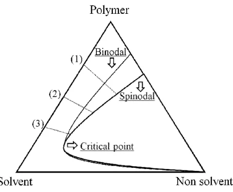
Figure 1.5– Carbon dioxide density vs temperature and pressure ... 9 Figure 1.6– General phase diagram for the system polymer/solvent/non-solvent with different
concentration paths. ... 11 Figure 1.7– Typical behaviour of a thermoresponsive polymer. PNIPAAm case: soluble in a
aqueous solution below the LCST and insoluble above this temperature ... 15 Figure 1.8 - Examples of thermoresponsive polymers based of PNIPAAm ... 16 Figure 1.9– Typical behaviour of a pH sensitive polymer acidic groups ... 17 Figure 1.10 - Representative pH-responsive polyacids; (a) poly(acrylic acid) (PAAc), (b)
poly(methacrylic acid) (PMAAc), (c) poly(2-ethyl acrylic acid) (PEAAc), (d) poly(2-propyl acrylic acid) (PPAAc). ... 17 Figure 1.11 - Representative pH-responsive polybases. (a) Poly(N,N-dimethyl aminoethyl
methacrylate) (PDMAEMA), (b) poly(N,N-diethyl aminoethyl methacrylate) (PDEAEMA), (c) poly(4 or 2-vinylpyridine) (PVP), (d) poly(vinyl imidazole). ... 18 Figure 1.12 – Drug levels in the blood with (a) traditional drug dosing and (b) controlled-delivery
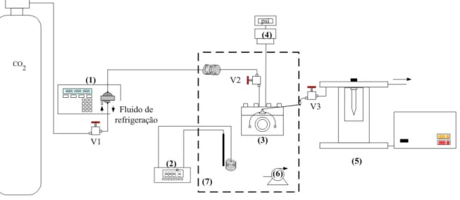
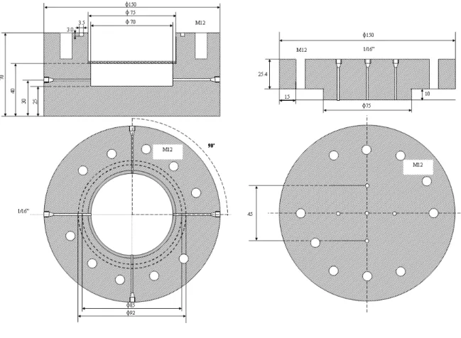
Figure 2.1 - Layout of the high-pressure apparatus for the membrane formation: (1) Gilson 305 piston pump; (2) temperature controller; (3) high-pressure cell; (4) pressure transducer (5) back Pressure Regulator ... 35 Figure 2.2 - Schematic representation of the new high pressure cell used for membrane
preparation. ... 36 Figure 2.3 – Polysulfone membrane obtained with the scCO2-assisted phase inversion method . 37
Figure 2.4 - Scanning electron micrographs of membranes cross sections obtained with fast depressurization. Solvents: a) chloroform; b) N,dimethylformamide; c) N, dimethylacetamide; d) N,dimethylpropionamide; e) dimethylsulfoxide; f) N-methylpyrrolidone. ... 39 Figure 2.5 - Pore size distribution of PS membranes produced using different solvents with a
depressurization in less than one minute. ... 40 Figure 2.6 - Influence of the solvent molecular size in the pore size diameter. ... 41 Figure 2.7 - Vapour liquid equilibrium of the mixtures carbon dioxide + chloroform, carbon
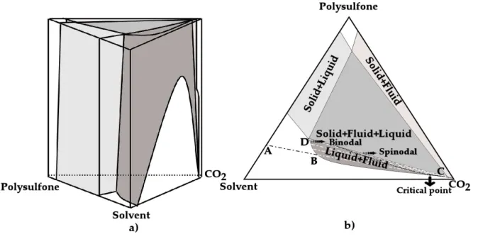
dioxide + N,N-dimethylformamide and carbon dioxide + N-methylpyrrolidone at 318.15 K. ... 45 Figure 2.8 - a) Schematic representation of an isothermal phase diagram for the ternary system
PS–solvent–CO2. Diagram is not to scale. b) Cross section of the ternary diagram at
pressures above the critical point of the binary mixture carbon dioxide + solvent. ... 46 Figure 2.9 - Scanning electron micrographs of PS membranes produced using chloroform as the
Figure 2.10 - Depressurization effect in the pore size distribution of PS membranes using two different solvents: a) chloroform b) N,N-dimethylacetamide. Doted line - slow depressurization; continuous line - fast depressurization ... 50 Figure 2.11 - Surface details of PS membranes. a) 45º cut (N,N-dimethylformamide and fast
depressurization) b) SEM picture of a pore in the surface (N,N-dimethylacetamide and slow depressurization). ... 54 Figure 2.12 - Scanning electron micrographs of the cross section of the membranes with different
PCL weight percentage: (a) 0 wt.%; (b) 10.3 wt.%; (c) 24.4 wt.%; (d) 40.4 wt.%; (e) 51.6 wt.%. ... 61 Figure 2.13 - Pore size cumulative distribution curves. ( ) – 0 wt.%; ( ) – 10.3 wt.%; ( )– 24.4
wt.%. ... 62 Figure 2.14 – DSC analysis of the blend membranes with different PCL weight percentage. ( ) –
0 wt.%; ( ) – 10.3 wt.%; – 24.4 wt.%.; (∇) 40.4 wt.%; (◆) 51.6 wt.%. ... 64 Figure 2.15 - DMA spectra of the prepared porous matrixes with different PCL compositions (see
legend). Tensile frequency scan experiments at room temperature where the storage modulus (a) and the loss factor (b) were recorded: ( ) – 0 wt.%; ( ) – 10.3 wt.%; – 24.4 wt.%.; (∇) 40.4 wt.%; (◆) 51.6 wt.%. ... 66 Figure 2.16 - (a) Different operational modes that can be used to introduce the co-solvent
(ethanol) in the non-solvent (CO2) stream. Hatched line-gradient mode; SEM pictures of
chitosan membranes prepared (b1) isocratic mode and (b2) gradient mode. ... 72 Figure 2.17 - SEM pictures of the membranes cross section prepared with different co-solvent
Figure 2.18 - Hypothetical ternary phase diagram for the system Polymer – Solvent – Non-solvent. a) Composition paths that can occur during membrane formation; b) Possible structure formation in the different paths of the gelation/vitrification region and liquid-liquid demixing gap: dense structure formation (1), nucleation and growth of droplets of the polymer lean phase with further solidification of the polymer-rich phase, leading to a cellular structure (2), bicontinuous morphology due to spinodal decomposition (3) microparticles due to nucleation and growth of droplets of the polymer-rich phase, followed by solidification of the polymer-rich phase (4). ... 80 Figure 2.19 - Stress-strain curves for chitosan membranes under a) dry conditions and b) wet
conditions (soaked in PBS for 1 h). ... 82 Figure 2.20 - Degradation of the different chitosan porous structures. (a) Lysozyme solution and
(b) Phosphate buffer solution. ... 84 Figure 2.21 - In vitro drug release profiles for chitosan membranes loaded with 40, 80 and 160
mg gentamicin /gchitosan ... 86 Figure 2.22 - Representative images of L929 fibroblast cells cultured on chitosan membranes
(2.5% isocratic) (a) and polystyrene control (b) after 3 days in culture, presenting their characteristic morphology. (c) Cytotoxicity tests of the chitosan membranes following the ISO standards for biomaterials. Negative control: tissue culture plate control (polystyrene); Positive control: 0.01 M phenol. ... 88 Figure 2.23 - Output of MSC culture on chitosan membranes (2.5% isocratic) in terms of fold
Figure 3.1 - Schematic representation of the apparatus used in the polymerisation reactions. 1- nitrogen cylinder; 2-gas regulator; 3-rupture disc; 4- high-pressure manometer; 5- check-valve; 6- line filter; 7-water bath; 8-immersible stirrer; 9-high pressure cell ... 104 Figure 3.2- Characterization of the PNIPAAm hydrogel polymerized without cross-linker a) 1H
NMR in CDCl3 b) MALDI-TOF MS spectrum. ... 108
Figure 3.3- Scanning electron microscopy images of the hydrogels prepared in different conditions. Samples: a) 0 wt% MBAM, b) 1.2 wt% MBAM, c) 2.4 wt% MBAM, d) 4.5 wt% MBAM. ... 109 Figure 3.4- DSC thermograms of the hydrogels prepared. 1- 0 wt% MBAM; 2- 1.2 wt% MBAM;
3- 2.4 wt% MBAM; 4- 4.5 wt% MBAM. ... 110 Figure 3.5- Equilibrium swelling at 37ºC and 25ºC for PNIPAAm hydrogels. 2- 1.2 wt% MBAM;
3- 2.4 wt% MBAM; 4- 4.5 wt% MBAM ... 111 Figure 3.6- Particle size distributions of the different samples. ... 113 Figure 3.7- SEM pictures of PNIPAAm hydrogel impregnated in a chitosan scaffold. ... 114 Figure 3.8 - Cloud point measurements apparatus scheme. HPC, high-pressure cylinder; MC,
manual controller; C, cell; M, manometer; DB, decantation blister. ... 118 Figure 3.9 - Comparison of experimental data (symbols) for the CO2 + HEMA system with
calculated data (solid lines) obtained with the Soave-Redlich-Kwong equation of state with kij = - 0.0085, λij = 0.004 and lij = - 0.003. The black symbols ( , and ) represent experimental data obtained in this study at 40ºC, 50ºC and 65ºC, respectively. ... 123 Figure 3.10 - 1H NMR spectrum for PHEMA ... 125 Figure 3.11 - NMR for the different HEMA-NIPAAm copolymers. Labelling according to Table
Figure 3.12 – Scanning electron microscopy images of the hydrogels prepared in different conditions. Samples: a) PHEMA 0; b) PHEMA 20; c) PHEMA 40; d) PHEMA 60; e) PHEMA 80; f) PHEMA 100. ... 127 Figure 3.13 – DSC thermograms of the thermoresponsive hydrogels prepared ... 128 Figure 3.14 – DSC thermograms of the PNIPAAm-PEO hydrogels ... 132 Figure 3.15 – Scanning electron microscopy images of the hydrogels prepared with different
monomer proportions. a) MAA 0; b) MAA 20; c) MAA 40; d) MAA 90; e) MAA 100 ... 137 Figure 3.16 – Equilibrium volume swelling ratio of a ) thermoresponsive hydrogels (MAA0,
MAA20 and MAA40) in a PBS solution at 37 °C as function of temperature and b ) Pulsatile swelling behavior in response to a stepwise pH change between 2.1 and 7.4 at 37°C. ... 138 Figure 3.17 – Fluorouacil release profiles for the PNIPAAm-co-MAA hydrogels at different pH
and temperature conditions. a) Temperature pulse effect at pH 7.4; b) pH pulse effect at 37ºC. ... 140 Figure 4.1- High-pressure apparatus for scaffold reticulation: (1) Gilson 305 piston pump; (2)
high pressure cell with crosslinker; (3) high pressure cell with the scaffolds; (4) pressure transducer; (5) temperature controller; (6) recirculation pump; (7) thermostated water bath; (8) back pressure regulator ... 153 Figure 4.2 - SEM pictures of CHT scaffolds. a) previous to impregnation/ coating; b) after
Figure 4.4- Equilibrium volume swelling ratio of CHT scaffolds and PNIPAAm coated scaffolds with a ) temperature pulses between 20°C and 37°C in PBS (pH=7.4); b ) pH pulses between 5.5 an 7.4 in a buffered solution at 37 °C. ... 160 Figure 4.5 - Biodegradability of the CHT scaffolds coated and non coated with PNIPAAm
(a)PBS with Lysozyme (b) PBS... 162 Figure 4.6 - a) Release of Ibuprofen from PNIPAAm coated CHT scaffolds; b) Different charges
that are present in the scaffold and in the drug in the tested conditions. ... 164 Figure 4.7 - Release of BSA from PNIPAAm coated CHT scaffolds. ... 167 Figure 4.8 - Schematic description of thermoresponsive membranes preparation methodology 171 Figure 4.9 - Schematic representation of the filtration cell. ... 174 Figure 4.10 - Scanning electron micrographs of: (a) membranes surface morphology and (b)
membranes cross section morphology. (1) unmodified polysulfone membranes and (2) PNIPAAm-coated membrane. ... 178 Figure 4.11 - Pore size distribution of membranes before and after coating with PNIPAAm. ... 179 Figure 4.12 - XPS spectrum of unmodified polysulfone membrane and polysulfone membrane
coated with PNIPAAm; (a) Sulphur (S 2p) peak, (b) Nitrogen (N 1s) peak, (c) Carbon (C 1s) peak and π→π transition. ... 180 Figure 4.13 - Temperature dependence for dynamic contact angle changes on polysulfone
membrane unmodified and coated with PNIPAAm. ... 182 Figure 4.14 - (a) Phosphate buffer solution flux variation with temperature; (b) a schematic
Figure 4.15 - (a) Diffusion cell experiment with 3 mg/ml BSA, pH 7.4 and 0.1M PBS at 20 and 40 ºC. (b) Effect of step temperature gradient on protein filtration. The curve fitting was performed according to the mathematical model developed in this work. ... 186 Figure 4.16 - Hydroxypropyl-beta-cyclodextrin chemical structure. R=CH2CHOHCH3 and H 192
Figure 4.17- Appearance of a PMMA membrane prepared with the CO2-assisted phase inversion
method. ... 194 Figure 4.18 - Scanning electron micrographs of a PMMA membrane produced: a) surface top
view; b) cross-section. ... 198 Figure 4.19 - Pore size distribution of PMMA membranes produced using different amounts of
HP- -CDs. Entries correspond to table 4.4. ... 199 Figure 4.20- Scanning electron micrographs of PMMA membranes produced with 9.2 wt% of
HP- -CDs in the casting solution: a) before; b) after impregnation. ... 200 Figure 4.21- Ibuprofen release profile from the different membranes into buffer solution pH 7.4.
List of Tables
Table 1.1 – Comparison of physical properties of gases, supercritical fluids and liquids ... 2
Table 1.2 - Critical properties of various solvents [3]. ... 2
Table 1.3- Resume of the materials that were processed by CO2 induced phase inversion method 7 Table 1.4 – Examples of stimuli-responsive hydrogels in drug delivery ... 12
Table 1.5- Examples of thermoresponsive polymers ... 14
Table 1.6 – Resume of new technologies for controlled drug delivery ... 20
Table 2.1- Solubility parameters and boiling points of the pure solvents. ... 42
Table 2.2 - Values of the critical temperatures (Tc), critical pressures (Pc) and acentric factors ( ) used in the PR-EOS... 43
Table 2.3 - Binary interaction parameters used in PR-EOS. ... 43
Table 2.4 - Solubility parameters for mixtures solvent–CO2 (5% w/w), estimated for 318.15 K and 18.6 MPa. ... 44
Table 2.5 - Water fluxes of PS membranes produced using different solvents with low and fast depressurization rate. ... 52
Table 2.6 - Effect of the different amounts of PCL in the water flux measurements and contact angles. ... 58
Table 2.7 - Enthalpy of melting of PCL phase, glass transition temperatures and melting ... 65
Table 2.8 - Influence of nonsolvent composition in devices morphology and water permeability. ... 79
Table 3.1 - Effect of cross-linker ratio on the PNIPAAm polymerization in scCO2. ... 105
Table 3.2 - Critical constants and accentric factor for CO2 and HEMA ... 120
Table 3.4 - Experimental results obtained in the polymerization of HEMA and NIPAAm and copolymerization of HEMA with NIPAAm. ... 124 Table 3.5 – Details of feed composition, sample designation for grafted polymers prepared and
experimental results obtained in the graft polymerization of EO and NIPAAm... 131 Table 3.6 - Formulations used for the synthesis, sample designations and experimental results
obtained in the copolymerisation of NIPAAm and MAA ... 134 Table 4.1 - Parameters used to adjust Fick law of diffusion to ibuprofen and BSA release ... 165 Table 4.2 - Bulk initial concentration, Cbi, monolayer adsorption capacity, qm, and Langmuir
constant or association constant, K, used in the model. ... 187 Table 4.3 - Estimated values for protein diffusion coefficient, D, pure water permeability, Lp, and
selectivity, σ, in this work. ... 188 Table 4.4- HP-β-CD content in the casting solution and in the produced membranes and
Resumo
Nas últimas três décadas a utilização de dióxido de carbono supercrítico (scCO2) tornou-se uma
alternativa atractiva para a produção e processamento de polímeros. O objectivo principal desta tese foi o desenvolvimento de estruturas porosas inteligentes utilizando tecnologia supercrítica. Esta tese está organizada em quatro capítulos principais. O primeiro revê e destaca algumas potencialidades da tecnologia supercrítica e os seguintes compilam o trabalho experimental e os resultados obtidos. O trabalho desenvolvido encontra-se dividido em três partes principais: na primeira (2º capítulo) é aplicado um processo de inversão de fases para a produção de estruturas porosas, nomeadamente membranas, em que o não solvente é o dióxido de carbono supercrítico; na segunda parte (3º capítulo) aborda-se a síntese de polímeros inteligentes, em especial polímeros sensíveis à temperatura e/ou pH; finalmente estas duas áreas são conjugadas (4º capítulo) com vista à produção de estruturas porosas inteligentes com propriedades físicas e químicas definidas. Todos os trabalhos têm em comum a preparação e o processamento de materiais biodegradáveis e/ou biocompatíveis para a obtenção de matrizes porosas, nomeadamente membranas e scaffolds, com morfologia controlada.
Para a preparação das membranas foi desenvolvida, no laboratório, uma nova instalação e uma nova célula de alta pressão. O primeiro estudo consistiu na preparação de membranas de polisulfona, um polímero biocompatível com largas aplicações na medicina, em especial em membranas de hemodiálise. Neste trabalho foi estudada a influência de dois parâmetros: a velocidade de despressurização no final do processo e a afinidade entre solvente e não solvente (CO2). A incorporação de um agente de expansão (policaprolactona) capaz de originar estruturas
liquefazê-lo a temperaturas relativamente baixas. Durante o processo de descompressão a libertação rápida do gás dá origem à formação de uma espuma que ao solidificar leva à formação de uma estrutura porosa.
Finalmente foram preparadas membranas e partículas de quitosano, um polímero derivado do 2º polímero natural mais abundante na Terra, a quitina. Estes dispositivos foram produzidos utilizando três dos mais promissores solventes amigos do ambiente (etanol, água e CO2). A sua
morfologia e a estrutura tridimensional foram controladas através da alteração da composição do co-solvente (etanol) no não solvente (CO2) durante o processo de inversão de fases. A análise por
microscopia electrónica permitiu verificar que a forma como o co-solvente é introduzido (modo isocrático ou modo gradiente) era relevante para a estrutura obtida. Uma das vantagens apresentadas por estes dispositivos é a sua baixa solubilidade em condições neutras de pH, mesmo sem se proceder a processos adicionais de tratamento, como seja a reticulação, o que permite aumentar a biocompatibilidade das estruturas preparadas. Por esta razão, as membranas foram testadas em termos de citotoxicidade e capacidade de adesão e proliferação de célula estaminais humanas do mesenquima. Após duas semanas de cultura verificou-se um aumento de 9 vezes no crescimento das células nas membranas de quitosano contra um aumento de 6 vezes no meio de controlo, preservando a sua capacidade de diferenciação.
Demonstrou-se ainda que o método de preparação em causa era capaz de preparar, num único passo, membranas para libertação controlada, apenas por co-dissolução de uma molécula modelo (gentamicina) na solução de quitosano utilizada para preparar a membrana.
O próximo objectivo desta tese consistiu na preparação de polímeros inteligentes. No capítulo 3 é apresentada a síntese em scCO2 de um dos polímeros sensíveis à temperatura mais estudados, o
estruturas porosas inteligentes. Para provar este conceito foram utilizados “scaffolds” de quitosano.
A temperatura baixa de transição crítica, denominada LCST, que para o PNIPAAm se encontra perto dos 32ºC foi também ajustada através da copolimerização ou grafting do NIPAAm com outros monómeros. A copolimerização com hidroxietilmetacrilato (HEMA) permitiu diminuir o LCST de 32.2 para aproximadamente 27.7ºC. A medição de pontos de nuvem a 40 ºC, 50 ºC e 65 ºC conjuntamente com a modelação efectuada utilizando a equação de estado Soave-Redlich-Kwong com a regra de mistura Mathias-Klotz-Prausnitz permitiu optimizar as condições para a reacção de polimerização.
Para aumentar o LCST, produziram-se polímeros de PNIPAAm por grafting com poli(óxido de etileno). Foram ainda preparados polímeros sensíveis a dois estímulos (temperatura e pH) através da copolimerização do PNIPAAm com ácido metacrílico. Através dos estudos de impregnação e libertação de drogas modelo testaram-se as capacidades destes hidrogéis para serem aplicados em libertação controlada de moléculas bioactivas.
Finalmente no capítulo 4 combinaram-se os trabalhos descritos nos capítulos 2 e 3 referentes à preparação de estruturas porosas e à síntese de polímeros inteligentes para produzir estruturas porosas inteligentes, com propriedades físico-químicas bem definidas: i) scaffolds de quitosano; ii) membranas de polisulfona termosensíveis e iii) membranas de polimetilmetacrilato.
livres) nomeadamente, a capacidade de incharem na presença de água em diferentes proporções consoante as condições de pH e temperatura do meio.
Estas estruturas foram ainda impregnadas com drogas/ proteínas modelo (ibuprofeno e bovine serum albumin), utilizando duas estratégias distintas: impregnação com fluídos supercríticos e incorporação na solução de preparação dos scaffolds. A libertação de ambos os compostos ocorreu após vários dias e prolongou-se durante várias semanas, revelando um padrão de acordo com as condições de pH e temperatura.
Esta mesma metodologia foi utilizada na preparação de membranas de polisulfona sensíveis à temperatura. Estas membranas foram preparadas segundo a técnica e o procedimento desenvolvidos no capítulo 2 em que o CO2 é utilizado como não solvente. A medida do fluxo de
água através destas membranas a várias temperaturas diferentes demonstrou que estas apresentam uma resposta rápida de abertura e fecho dos poros quando a temperatura ultrapassa o LCST. O mecanismo de abertura e fecho dos poros devido a variações de temperatura foi testado utilizando uma proteína modelo (BSA). Foi possível verificar que com mudanças de temperatura era possível controlar a difusão da proteína através da estrutura porosa. Desenvolveu-se um modelo de difusão baseado na lei de Fick e na adsorção de Langmuir para descrever o mecanismo de libertação através da membrana.
Finalmente foram preparadas membranas de poli(metilmetacrilato) contendo hidroxipropil -ciclodextrinas (HP- -CDs) para aplicação em sistemas de libertação controlada. As membranas foram preparadas com HP- -CD numa gama de 0 a 33.4% (p/p) através da incorporação destas na solução utilizada para preparar as membranas. A impregnação com um fármaco modelo (ibubrofeno), através de utilização de CO2 como solvente permitiu a preparação de membranas
através da quantidade de ciclodextrina incorporada na membrana, representando uma alternativa para a preparação de estruturas porosas inteligentes.
Os materiais e os processos desenvolvidos nesta tese demonstram que o CO2 supercrítico pode
Abstract
Over the past three decades the use of supercritical carbon dioxide (scCO2) has received much
attention as a green alternative in the synthesis and processing of polymers. The scope of this thesis is the development of biocompatible and “smart” porous structures using CO2-assisted
processes.
This thesis is organized in four main chapters. The first one reviews and highlights some potentialities of supercritical fluid technology and the following ones compile the experimental work developed. The work is divided in three main parts: in the first part (2nd chapter) a CO2
-assisted phase inversion method was developed in order to prepare porous structures, namely membranes. In the second part (3rd chapter) the focus was the synthesis of “smart” polymers, especially thermo and pH sensitive polymers. Finally, these two areas were combined (4th chapter) for the preparation of “smart” porous structures. The common guide line was the preparation or processing of biodegradable and/or biocompatible materials with special emphasis on the preparation of porous matrices, namely membranes and scaffolds, with controlled morphology.
For membrane preparation a new high pressure apparatus and a new high pressure cell were developed. Polysulfone membranes (a biocompatible polymer with numerous applications in the medical field) were prepared and the effect of the solvent affinity and depressurization rate in the morphology and in the performance in terms of pure water flux of the membranes was investigated. The incorporation of a foaming agent was also analyzed and the high pressure CO2
to the low affinity between water and CO2. To induce the phase inversion a co-solvent (ethanol)
was introduced in the CO2 stream. The obtained devices (membranes and beads) were fabricated
using moderate temperatures and “green” solvents (ethanol, water and CO2). The morphology
and the three dimensional (3D) structures were controlled by altering the co-solvent (ethanol) composition in the CO2 non-solvent stream during the demixing induced process.
Microarchitectural analysis by scanning electron microscopy identified the formation of particulate agglomerates when 10% of ethanol in the scCO2 stream was used and detected the
development of porous membranes with different morphologies and mechanical properties depending on the programmed gradient mode and the entrainer percentage (2.5-5%) added to the scCO2 stream. These chitosan matrices exhibited low solubility at neutral pH conditions, with no
further modifications, demonstrating their applicability in bioreactors as static (membranes) or stirred (beads) culture devices. It was also demonstrated that the current method is able to prepare, in a single-step, an implantable antibiotic release system by co-dissolving gentamicin with chitosan and the solvent. In addition, the cytotoxicity as well as the ability of these structures to support the adhesion and proliferation of human mesenchymal stem cells (hMSC) in vitro were also addressed. After 2 weeks in culture, a 9-fold increase was obtained (versus 6 of the control). More importantly, cells maintained their clonogenic potential and immunophenotype (>95% CD 105+ Cells after 7 days of culture). In this chapter, a hypothetical schematic ternary diagram for the systems polymer–solvent–CO2 is used to discuss and explain the results.
Another goal of this thesis was the synthesis of “smart” polymers. Chapter 3, addresses the precipitation polymerization of a thermoresponsive hydrogel, poly(N-isopropylacrylamide) (PNIPAAm), in scCO2. This hydrogel has a transition temperature, hereinafter called low critical
suggested, in order to further extend the applications of membranes or porous bulky systems. The in situ synthesis of PNIPAAm within a chitosan scaffold was tested as a proof of concept, in
order to produce smart partially-biodegradable scaffolds for tissue engineering applications. The LCST was tuned by copolymerization or graft polymerization of NIPAAm with other monomers. Copolymerization with hydroxyethyl methacrylate (HEMA) was used to decrease the LCST temperature from 32.2 ºC to approximately 27.7 ºC. Cloud point measurements of CO2 +
HEMA system were used to optimize the polymerization temperature. Experimental data were obtained at 40 ºC, 50 ºC and 65 ºC and pressures up to 21.1 MPa. Soave-Redlich-Kwong equation of state with Mathias-Klotz-Prausnitz mixing rule was used to model experimental results and a good correlation was achieved.
To increase the LCST, polyethylene oxide (an hydrophilic polymer) was grafted to PNIPPAAm. Dual stimulus (thermo and pH responsive) hydrogels were also prepared by copolymerizing methacrylic acid with PNIPAAm. As a proof of concept fluorouracil was incorporated in the hydrogels network and their release was controlled by temperature and pH stimulus.
In chapter 4 the concepts of the previous chapters were put together envisaging the preparation of “smart” functional polymeric devices with targeted physical and chemical properties namely: (i) chitosan-based dual stimulus scaffolds (temperature and pH responsive); (ii) polysulfone-based thermoresponsive membranes and (iii) polymethylmethacrylate-based membranes.
The chitosan scaffolds (pH sensitive) were coated/impregnated with a thermoresponsive polymer, poly(N-isopropylacrylamide) (PNIPAAm), using scCO2 as a carrier to homogeneously distribute
Microarchitectural analysis by scanning electron microscopy and mercury intrusion porosimetry proved that the coating of the inner pore structure was efficiently achieved without a considerable loss of porosity. Two different strategies were used to upload the porous structures with target molecules: supercritical fluid impregnation to impregnate with a low molecular weight model drug (ibuprofen) and bulk loading for a model protein (bovine serum albumin, BSA). Both for ibuprofen and BSA the release appeared after several days and prolonged for several weeks. The release profiles showed a specific pattern accordingly to the parameters (pH and temperature). The same methodology was used to prepare thermoresponsive polysulfone (PS) membranes. PS membranes were prepared using the CO2-assisted phase inversion method using the procedure
described in the previous chapters. Their pores were coated/impregnated with a thermoresponsive polymer - poly(N-isopropylacrylamide) using the same approach that was applied for the chitosan scaffolds. The on/off mechanism was tested using a model protein (BSA) as a proof of concept for the ability to control pore aperture by temperature stimulus. A diffusion model based on Fick`s law and Langmuir adsorption was developed.
The last application was the preparation of cyclodextrins-containing polymers that have proved themselves to be useful for controlled release. For that, poly(methylmethacrylate) (PMMA) membranes were prepared containing hydroxypropyl- -cyclodextrins (HP- -CDs) for potential application as drug delivery devices. The polymeric membranes were obtained with HP- -CD contents ranging from 0 to 33.4 wt%, by changing the composition of the casting solution, and were further impregnated with ibuprofen using scCO2 in batch mode. The influence of the
membrane functionalization in the controlled release of ibuprofen was studied by performing in vitro experiments in buffer solution pH at 7.4. The release of the anti-inflammatory drug could be
The materials and processes developed in the present work demonstrate that supercritical CO2
can play a major role for the synthesis and preparation of a range of well defined porous polymeric structures that could have applicability in both biomedical and biotechnological fields. It demonstrates that it is possible to transport monomers, active molecules and drugs with high efficiency and at the same time to prepare new structures that could be utilized as a platform for different applications.
Chapter 1
1.
Introduction
The emergent demand in medicine and in the biomaterial field for materials with a more efficient therapeutic activity and without any contaminants has driven research to find new molecules and new synthetic approaches to produce and process polymers. Supercritical fluids (SCF) have assumed an important role, during the last two decades, as an efficient alternative not only by the environmental aspect, but also due to a number of specific physical, chemical and toxicological advantages that offer the opportunity to manipulate the outcome of reactions, including the polymer structure [1].
A supercritical fluid is any substance at a temperature and pressure above its thermodynamic critical point (pressure and temperature) but below the pressure at which the fluid will solidify (Figure 1.1) [2].
In general terms, supercritical fluids have properties (viscosity, diffusivity and density) between those of a gas and a liquid, tuneable through the control of pressure and temperature (Table 1.1) [3].
Table 1.1 – Comparison of physical properties of gases, supercritical fluids and liquids
Density (Kg/m3) Viscosity (cP) Diffusivity (mm2/s
Gases 1 0.01 1-10
Supercritical 100-1000 0.05-0.1 0.01-0.1
Liquids 1000 0.5-1.0 0.001
Several substances can be used as supercritical fluids. In Table 1.2 it is presented some of the critical properties of the most commonly used fluids.
Table 1.2 - Critical properties of various solvents [3].
Solvent Critical temperature (K) Critical pressure (MPa)
Carbon dioxide 304.1 7.38
Water 647.3 22.12
Ethane 305.3 4.87
Ethylene 282.4 5.04
Propane 369.8 4.25
Methanol 512.6 8.09
Acetone 508.1 4.70
Supercritical fluids and specially supercritical carbon dioxide (scCO2) have found applications in
a broad range of areas [4]: extraction [5], polymerization [6, 7], particle design [8, 9], chemical reactions [10], drug impregnation [11], formation of porous structures [12, 13], dry cleaning [14], etc. In this thesis special attention will by given for polymer synthesis and processing, particularly the formation of porous structures and synthesis of “smart” polymers in scCO2.
1.1 Porous structures
There are several reasons to consider SCF an alternative medium for the synthesis and processing of porous materials. Besides its environmental advantages, scCO2 allows the production of a dry
polymeric product (CO2 is a gas under ambient conditions) [15, 16], introduces additional
parameters (pressure, temperature, depressurization) to control membranes morphology, improves mass transfer (much lower viscosities than organic liquids, and easily adjusted with variations in pressure and temperature) [17] and reduces the solvent recovery costs. Surface modification of porous materials can be facilitated because SCF and in particular CO2 are
extremely versatile wetting agents due to their low surface tension (e.g.., liquid CO2 will wet
Teflon) and pore collapse can also be avoided because SCF do not give rise to a liquid-vapour interface.
During the years several techniques have been applied for the preparation of porous structures using SCF technology but the main processes are: foaming, emulsion templating and CO2
assisted phase inversion method [12].
1.1.1 Foaming
transition temperature (Tg) found for many polymers in the presence of CO2 [21, 22, 23, 24]
which means that the polymer may be kept in the liquid state at relatively low temperatures. Polymer foams are formed when a polymer, plasticized by saturation in the supercritical fluid is rapidly depressurized at a constant temperature. As pressure is released pockets of gas nucleate and grow in the polymer. As the supercritical fluid leaves the polymer, the Tg increases, generating nuclei due to supersaturation, which will grow to form the cellular structure until vitrification occurs. Figure 1.2 gives a schematic representation of the foaming process.
Swollen
Polymer
CO
2Sorption
Depressurization
Figure 1.2 - Schematic representation of the foaming process using scCO2.
1.1.2 Emulsion templating
Emulsion templating is a versatile method for the preparation of well-defined porous polymers [31, 32] and inorganic materials [33]. The technique involves two steps: formation of a high internal phase emulsion and locking the structure of the external phase, usually by reaction induced phase separation (e.g., sol-gel chemistry, free-radical polymerization). Subsequent removal of the internal phase (i.e., the emulsion droplets) gives rise to a skeletal replica of the emulsion. This final step is very critical due to the fact that the internal oil phase (often an organic solvent) must be removed from the porous structures. Cooper and co-workers [34, 35] have developed a process for emulsion templating without volatile organic solvents, using only water and CO2. CO2 being a gas under normal pressure/conditions can be removed easily by
depressurization.
Figure 1.3– Schematic representation of the CO2/Water emulsion templating process. Adapted from [35]
Several organic and inorganic porous matrixes were obtained using this technique: polyacrylamide [35], calcium Alginate hydrogels [36], silica [37], poly(vinyl alcohol) and naturally derived chitosan [38], dextran [39], etc.
1.1.3 CO2 assisted phase inversion
A number of different techniques are available to prepare porous polymeric films, such as sintering, stretching, track etching, phase separation, sol-gel process, vapour deposition and solution coating. However, the majority of porous flat membranes are prepared from a homogenous polymer solution by the wet-phase inversion method in which a polymer solution (polymer plus solvent) is cast on a suitable support and immersed in a coagulation bath containing a solvent. Since the precipitation occurs due to the exchange of solvent and non-solvent, the correct choice of the pairs of solvents is a very important parameter to control the morphology of the membrane. Other important preparation parameters are: polymer concentration, temperature, humidity, evaporation time, and the composition of the casting solution (e.g. additives) [40].
Figure 1.4 - Schematic description of the CO2 induced phase inversion method
Kho et al. [41] were the first ones to report the preparation of membranes of a semicrystalline polyamide, Nylon 6, by exposing a 2,2,2-trifluoroethanol solution to scCO2 to induce the phase
separation of the polymer solution. Since then many authors have been applied to produce membranes of different materials as presented in Table 1.3.
Table 1.3- Resume of the materials that were processed by CO2 induced phase inversion method
Authors Polymer Analysed effect
Kho et. al [41] Polyamide (Nylon 6)
Polymer concentration, temperature and pressure.
Matsuyama et. al [42]
Polystyrene
Polymer concentration, temperature and pressure.
Matsuyama et. al [43]
Cellulose acetate Solvent - nonsolvent affinity
E. Reverchon and
Cellulose acetate
E. Reverchon and S. Cardea [45]
Polysulfone
Polymer concentration, temperature and pressure.
E. Reverchon et. al [46]
Poly (methyl methacrylate)
Polymer concentration, temperature and pressure.
E. Reverchon and S. Cardea [47]
Poly(vinylidene fluoride)-co- hexafluoropropylene
Polymer concentration, temperature and pressure.
Reverchon et. al [48]
Poly(vinyl alcohol)
Polymer concentration, temperature, pressure, addition of an entrainer to the
solvent.
Reverchon et. al [49]
Poly(vinyl alcohol)
Polymer concentration, temperature, pressure and different ethanol:CO2
ratios for the Phase inversion, Tsivintzelis et. al
[50]
Poly(l-lactic acid)
Polymer concentration, temperature and pressure.
Xu et. al [51] Polylactide
Polymer concentration, solvent affinity, depressurization rate and
non-solvent composition.
Huang et. al [52] Poly(vinylidene fluoride)
Polymer concentration, temperature, pressure and addition of poly(methyl methacrylate) in the casting solution.
Li et. al [53] Poly(vinyl butyral)
Polymer concentration, temperature, pressure and depressurization. Temtem et. al
[54]
Polysulfone
Temtem et. al [55]
Blends of polysulfone-polycaprolactone
Foaming vs phase inversion.
Temtem et. al [56]
Chitosan Entrainer effect.
When the solution of polymer is first immersed as a film into a coagulation bath rapid changes occur and usually a skin forms at the interface. As time proceeds, changes in the concentration occur in the layers further away from the interface, but these occur less rapidly than the interfacial changes. The rate at which the changes occur in the sub-layers has a profound effect on the structure. The ‘tuneable’ solvent power of the supercritical fluid, owing to its variable (with pressure or temperature) solvent density and viscosity is a serious advantage when compared with the traditional solvents.
0 200 400 600 800 1000 1200
0 50 100 150 200 250 300 350 400
pressure [bar]
d
e
n
s
it
y
[k
g
/m
3]
0 C 20 C 40 C 60 C 80 C 100 Ck
P two- phase-region bFigure 1.5 shows the density-pressure phase diagram for carbon dioxide. One of the particularities of the critical point is that close to it a small increase in pressure or temperature causes a large increase in the density. This property is very important for the phase inversion process because it is closely related with the nonsolvent (CO2) strength and it is known that the
manipulation of the strengths of the solvent and nonsolvent is one of the primary means to control the properties of membranes formed by this process. Many authors have analysed the influence of these two parameters in membrane morphology (Table 1.3) and they all observed that the average pore size and membrane porosity decreased by increasing the pressure or decreasing the temperature [41, 42, 44, 45, 46, 47, 48, 49, 50, 52, 53].
A change in these two parameters will modify the phase diagram of the ternary system polymer/solvent/non-solvent, pressure and temperature dependent. In the analyses of these diagrams it is usually assumed a hypothetic diagram due to the inexistence of experimental data (vapour-liquid, liquid-liquid and solid-fluid). In this thesis a similar analysis will be performed on Chapter 2. Typically, a simple rule, is that higher CO2 densities (high strength) will induce the
formation of a large number of nucleation points, inducing the formation of small pores in a large quantity. In opposition smaller densities will produce very few nucleation points that will be responsible for the formation of large pores in small quantity.
CO2-assisted phase inversion also guides with the same rules of the conventional process which
Figure 1.6– General phase diagram for the system polymer/solvent/non-solvent with different concentration
paths.
Increasing the polymer concentration in the starting solution, i.e., passing from point 3 to
1 the operative point (the intersection between the tie-line and the composition path) shifts towards the polymer rich phase. Therefore, using the lever rule, we can observe that the polymer-lean phase decreases. As a consequence membranes will be produced with a larger number of pores but with a small diameter.
Other parameters, such as the depressurization rate or the ability of CO2 to liquefy polymers have
1.2 “Smart” hydrogels
Another main research area explored in this work was the preparation and processing of smart polymers, particularly thermoresponsive and pH-sensitive hydrogels.
The last two to three decades have witnessed explosive growth in the synthesis and processing of smart polymers. They were widely used in the biomedical field due to their tuneable chemical and three-dimensional physical structure, biocompatibility properties and possibility to respond external stimulus, such as pH , temperature, ionic strength, and electric field [57]. Table 1.4 it is presents some examples of stimuli-responsive hydrogels used in drug delivery.
Table 1.4 – Examples of stimuli-responsive hydrogels in drug delivery
Stimuli Polymer Drug Ref
Magnetic field Ethylene-co-vinyl acetate Insulin [58]
Electric Field
Poly(2-hydroxyethyl methacrylate)
Propranol [59]
Glucose Ethylene-co-vinyl acetate Insulin [60]
Urea
Methyl vinyl ether-co-maleic anhydride
Hydrocortisone [61]
Morphine
Methyl vinyl ether-co-maleic anhydride
Naltrexone
22 [62]
pH Chitosan-poly(ethylene oxide)
hydrochloride pH Poly(acrylamide-co-maleic acid) Terbinafine, hydrochloride [65] pH N-vinyl pyrrolidone, polyethylene, glycol diacrylate,
chitosan
Theophylline, 5- Fluoroacil
[66]
Temperature Poly(N-isopropyl acrylamide) Heparin [67]
Temperature and pH
Poly(N-isopropyl acrylamide-co-butyl
methacrylate-co-acrylic acid)
Calcitonin [68]
1.2.1 Temperature responsive polymers
Temperature is the most widely used stimulus in environmentally responsive polymer systems not only because they are relatively easy to control, but also easily applicable both in vitro and in vivo.
Some hydrogels exhibit a separation from solution and solidification above a certain temperature. This threshold is defined as the lower critical solution temperature (LCST). Below the LCST, the polymers are soluble. Above the LCST, they become increasingly hydrophobic and insoluble, leading to gel formation. In contrast, hydrogels that are formed upon cooling of a polymer solution have an upper critical solution temperature (UCST). However, most applications are related to LCST based polymer systems [69,70].
attributed to the higher entropy term (∆S) with respect to the increase in the enthalpy term (∆H) in the thermodynamic relation ∆G = ∆H-T∆S. The entropy increases due to water–water associations which are the governing interactions in the system. In Table 1.5 it is presented some examples of thermoresponsive polymers.
Table 1.5- Examples of thermoresponsive polymers
Thermoresponsive polymer Obs.
Poly(N-isopropylacrylamide) It is the most studied thermoresponsive polymer.
Methylcellulose [71]
It gells at temperatures in the range of 60–80 ºC and turns into a solution upon cooling.
Poly(N-vinylisobutylamide) [72] -
Poly(vinyl methyl ether)[73] It has a LCST at moderate temperature ~35 °C.
Poly(N-vinylcaprolactam) [74]
Shows a dissolution/precipitation transition in water at temperatures close to physiological temperatures
(30±40 ºC)
Gelatin [75]
By cooling the temperature the chains transform their conformation from random coil to triple-helix, during
which physical junctions are promoted and gel networks occur.
Gellan benzyl ester [76]
Double helix conformations via hydrogen bonding in aqueous systems
Elastin-like polypeptides
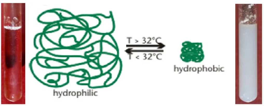
Poly(N-isopropylacrylamide), PNIPAAm, is probably the most studied thermoresponsive hydrogel. It has low critical solution temperature (LCST), around 32 ºC in an aqueous solution [77, 78], close to body temperature and dissolves in water below the LCST; precipitates from the aqueous solution above the LCST due to the disruption of hydrogen bonding with water and the increasing hydrophobic interactions among isopropyl groups (Figure 1.7). Due to this unique property, PNIPAAm gels have been widely used in biomedical fields, for example, as matrices in protein-ligand recognition, in drug controlled release, in enzyme and cell immobilization and in artificial organs / cell sheet technology [79, 80, 81, 82, 83, 84] .
Figure 1.7– Typical behaviour of a thermoresponsive polymer. PNIPAAm case: soluble in a aqueous solution
below the LCST and insoluble above this temperature
Figure 1.8 - Examples of thermoresponsive polymers based of PNIPAAm
In general, as the polymer chain contains more hydrophobic constituents the LCST becomes lower. Copolymerization of NIPAAm with a more hydrophilic monomer increases the overall hydrophilicity of the polymer, and the stronger polymer–water interactions lead to an increase in the LCST. Likewise, copolymerization with a more hydrophobic monomer results in a lower LCST than PNIPAAm [85]. Moreover, the phase transition temperature is influenced by the presence of salts [86] and pH to a certain extent [87].
A good review about the functional copolymers of NIPAAm for bioengineering applications can be found in the literature [88].
1.2.2 pH-sensitive polymers
All the polymers containing pendant groups that either accept or release protons in response to changes in environmental are pH sensitive polymers. Such materials, called polyelectrolytes, swell or collapse depending on the pH of their environment.
There are two kinds of pH sensitive materials: one which have acidic group (-COOH, -SO3H) and
swell in basic pH (Figure 1.9), and others which have basic groups (-NH2) and swell in acidic pH.
Figure 1.9– Typical behaviour of a pH sensitive polymer acidic groups
The response is triggered due to the presence of ionisable functional groups (like -COOH, -NH2)
which get ionized and acquire a charge (+/-) in a certain pH. As the environmental pH changes, the degree of ionization in a polymer bearing weakly ionizable groups is dramatically altered at a specific pH that is called pKa. This rapid change in net charge of pendant groups causes an alternation of the hydrodynamic volume of the polymer chains. The transition from collapsed state to expanded state is explained by the osmotic pressure exerted by mobile counterions neutralizing the network charges. There are two types of pH-responsive polyelectrolytes; weak polyacids and weak polybases.
Examples of pH sensitive polymers that are polyacids and polybases are represented in Figure 1.10 and in Figure 1.11.
Figure 1.10 - Representative pH-responsive polyacids; (a) poly(acrylic acid) (PAAc), (b) poly(methacrylic
Figure 1.11 - Representative pH-responsive polybases. (a) Poly(N,N-dimethyl aminoethyl methacrylate)
(PDMAEMA), (b) poly(N,N-diethyl aminoethyl methacrylate) (PDEAEMA), (c) poly(4 or 2-vinylpyridine)
(PVP), (d) poly(vinyl imidazole).
1.3 “Smart” drug/biomolecule delivery devices
The field of drug delivery is developing rapidly and is gaining the attention of scientists, pharmaceutical makers and industry.
The final aim of pharmacy and medicine is the delivery of any drug at the right time in a safe and reproducible manner to a specific target at the required level [89]. With traditional tablets or injections, the drug level in the blood follows the profile shown in Figure 1.12. a), in which the level rises after each administration of the drug and then decreases until the next administration. The problem consists in the fact that the blood level of the agent should remain between maximum values, which may represent a toxic level, and a minimum value, below which the drug is no longer effective. In controlled drug delivery systems designed for long-term administration, the drug level in the blood follows the profile shown in Figure 1.12. b), remaining constant, between the desired maximum and minimum, for an extended period of time.
Figure 1.12 – Drug levels in the blood with (a) traditional drug dosing and (b) controlled-delivery dosing.
Another issue is the fact that patients do not always follow the doctor’s orders, so there is a concern about patients’ compliance.
In the last decades several systems were developed in order to overcome these issues.
Table 1.6 – Resume of new technologies for controlled drug delivery
Technology Application Description
Drug polymer conjugates [90]
Prepare a form of insulin that can be
given orally.
Low molecular weight polymers (PEG) are attached to specific sites on drug molecules to
create drug–polymer conjugates Usage of
absorption enhancers [91]
Pulmonary drug delivery
Chitosan powder was tested for
the nasal administration of insulin and morphine
Iontophoresis and Ultrasound [92]
Transdermal drug delivery
Administration of iontocaine for local dermal anesthesis Micelles and liposomes [93] Encapsulation of therapeutic active molecules
Transport molecules unto the interior of cells
Drug releasing chambers [94]
Diabetes, cancer and for a range of target sites (i.e. eye, brain)
Delivery of potent drugs for extended periods.
Nanoparticles [95]
Nanoparticles that can become nanopills taking drugs through diminutive capillaries into the cell's internal machinery
Herein it is reported the development of a new strategy that could be applied in the preparation of smart porous structures with application as controlled delivery devices.
hydrogels inside the porous structures; (iii) the possibility to impregnate the smart devices with a non-residue technology; (iv) the potential of these smart devices to be used in controlled drug release.
1.4 References
[1] E.J. Beckman, Supercritical and near-critical CO2 in green chemical synthesis and processing.
J. Supercrit. Fluids 28 (2004) 121-191.
[2] P. Jessop, W. Leitner, Chemical Synthesis using supercritical fluids, Wiley-VCH, New York,
1999.
[3] R.C. Reid, J.M. Prausnitz, B.E. Poling, The properties of gases and liquids. 1987:
Mc-Graw-Hill.
[4] M. Perrut, Supercritical Fluid Applications: Industrial Developments and Economic Issues, Ind. Eng. Chem. Res. 39 (2000) 4531-4535.
[5] P. C. Simões, P. J. Carmelo, P. J. Pereira, J. A. Lopes, M. Nunes da Ponte, G. Brunner, Quality assessment of refined olive oils by gas extraction. J. Supercrit. Fluids 13 (1998) 337-341.
[6] P. Christian, M.R. Giles, R.M.T. Griffiths, D.J. Irvine, R.C. Major, S.M. Howdle, Free Radical Polymerization of Methyl Methacrylate in Supercritical Carbon Dioxide Using a Pseudo-Graft Stabilizer: Effect of Monomer, Initiator, and Stabilizer Concentrations. Macromolecules, 33 (2000) 9222–9227.
[7] J. M. DeSimone, E. E. Maury, Y. Z. Menceloglu, J. B. McClain, T. J. Romack, and J. R. Combes, Dispersion Polymerizations in Supercritical Carbon Dioxide. Science 265 (1994)
356-359.
[9] Z. Knez, E. Weidner, Particles formation and particle design using supercritical fluids. Current Opinion in Solid State and Materials Science 7 (2003) 353–361.
[10] E. Bogel-ukasik, I. Fonseca, R. Bogel-ukasik, Y. A. Tarasenko, M. Nunes da Ponte, A. Paiva and G. Brunner Phase, equilibrium-driven selective hydrogenation of limonene in high-pressure carbon dioxide. Green Chem. 9 (2007) 427 – 430.
[11] A.R.C. Duarte, M. S. Costa, A. L. Simplício, M. M. Cardoso and C. M.M. Duarte, Preparation of controlled release microspheres using supercritical fluid technology for delivery of anti-inflammatory drugs. Int. J. Pharm. 308 (2006) 168-174.
[12] A.I. Cooper, Porous Materials and Supercritical Fluids. Adv. Mater. 15 (2003) 1049-1059.
[13] J.J.A. Barry, H.S. Gidda, C.A. Scotchford, S.M. Howdle, Porous methacrylate scaffolds: supercritical fluid fabrication and in vitro chondrocyte responses. Biomaterials 25 (2004)
3559-3568.
[14] M. Sousa, M. João Melo, T. Casimiro and A. Aguiar-Ricardo, The art of CO2 for art
conservation: a green approach to antique textile cleaning. Green Chem. 9 (2007) 943- 947.
[15] T. Casimiro, A.M. Banet-Osuna, A.M. Ramos, M. Nunes da Ponte and A. Aguiar-Ricardo, Synthesis of highly cross-linked poly(diethylene glycol dimethacrylate) microparticles in supercritical carbon dioxide, Eur. Polym. J., 41 (2005) 1947-1953.
[16] M.R. Giles, R.M.T. Griffiths, A. Aguiar-Ricardo, M.M.C.G. Silva and S.M. Howdle, Fluorinated graft stabilizers for polymerization in supercritical carbon dioxide: the effect of stabilizer architecture. Macromolecules, 34 (2001) 20-25.
[18] J. E. Martini, The Production and Analysis of Microcellular Foam. Ph.D. Thesis, Massachusetts Institute of Engineering, 1981.
[19] S.K. Goel, E.J. Beckman, Generation of microcellular polymers using supercritical CO2.
Cellular Polymers 12 (1993) 251 -274.
[20] D.J. Mooney, D.F. Baldwin, N.P. Suh, L.P. Vacanti, R. Langer, Novel approach to fabricate porous sponges of poly(D,L-lactic-co-glycolic acid) without the use of organic solvents. Biomaterials 17 (1996) 1417-1422.
[21] S.K. Goel, E.J. Beckman, Generation of microcellular polymeric foams using supercritical carbon dioxide. Cell-growth and skin formation. Polym. Eng. Sci. 34 (1994) 1148–1156.
[22] S.K. Goel, E.J. Beckman, Generation of microcellular polymeric foams using supercritical carbon-dioxide.1. Effect of pressure and temperature on nucleation. Polym. Eng. Sci. 34 (1994)
1137–1147.
[23] P.D. Condo, K. P. Johnston, In situ measurement of the glass transition temperature of polymers with compressed fluid diluents. J. Poly. Sci., Part B, Poly. Phys. 32 (1994) 523-533.
[24] P. D. Condo, I. C. Sanchez, C. G. Panayiotou, K. P. Johnston, In situ measurement of the glass transition temperature of polymers with compressed fluid diluents. Macromolecules 25 (1992) 6119-6127.
[25] M.H. Sheridan, L.D. Shea, M.C. Peters; D.J. Mooney, Bioabsorbable polymer scaffolds for tissue engineering capable of sustained growth factor delivery. J. Control. Release 64 (2000) 91–
102.
[27] B. Krause, R. Mettinkhof, N.F.A. van der Vegt, M. Wessling, Microcellular Foaming of Amorphous High-Tg Polymers Using Carbon Dioxide. Macromolecules 34 (2001) 874-884.
[28] B. Krause, H. J. P. Sijbesma, P. Münüklü, N. F. A. van der Vegt, M. Wessling Bicontinuous Nanoporous Polymers by Carbon Dioxide Foaming. Macromolecules 34 (2001) 8792 -8801.
[29] S. Siripurapu, Y.J. Gay, J.R. Royer, J.M. DeSimone, R.J. Spontak, S.A. Khan, Generation of microcellular foams of PVDF and its blends using supercritical carbon dioxide in a continuous process. Polymer 43 (2002) 5511-5520.
[30] M.T. Liang, C.M. Wang, Production of engineering plastics foams by supercritical CO2. Ind.
Eng. Chem. Res. 39 (2000) 4622-4626.
[31] P. Hainey, I. M. Huxham, B. Rowatt, D. C. Sherrington, L. Tetley, Synthesis and Ultrastructural Studies, of Styrene-Divinylbenzene Polyhipe Polymers. Macromolecules 24 (1991) 117-121.
[32] A. Barbetta, N. R. Cameron, S. J. Cooper, High internal phase emulsions (HIPEs) containing divinylbenzene and 4-vinylbenzyl chloride and the morphology of the resulting PolyHIPE materials. Chem. Commun. 3 (2000) 221-222.
[33] A. Imhof, D. J. Pine, Uniform Macroporous Ceramics and Plastics by Emulsion Templating. Adv. Mater. 10 (1998) 697-700.
[34] R. Butler, C. M. Davies, A. I. Cooper, Emulsion Templating Using High Internal Phase Supercritical Fluid Emulsions. Adv. Mater. 13 (2001) 1459-1463.
[35] R. Butler, I. Hopkinson, A. I. Cooper, Synthesis of Porous Emulsion-Templated Polymers Using High Internal Phase CO2-in-Water Emulsions. J. Am. Chem. Soc. 125 (2003)
[36] S. Partap, I. Rehman, J. R. Jones, and J. A. Darr, “Supercritical carbon dioxide in water" emulsion-templated synthesis of porous calcium alginate hydrogels. Adv. Mater. 18 (2006) 501–
504.
[37] J. Wang, Y. Xia, W. Wang, R. Mokaya and M. Poliakoff, Synthesis of siliceous hollow spheres with large mesopore wall structure by supercritical CO2-in-water interface templating. Chem. Commun. 2 (2005) 210–212.
[38] J.-Y. Lee, B. Tan, and A. I. Cooper, CO2-in-Water Emulsion-Templated Poly(vinyl alcohol)
Hydrogels Using Poly(vinyl acetate)-Based Surfactants. Macromolecules 40 (2007) 1955-1961.
[39] C. Palocci, A. Barbetta, A.L. Grotta, and M. Dentini, Porous Biomaterials Obtained Using Supercritical CO2-Water Emulsions. Langmuir 23 (2007) 8243-8251.
[40] M. Mulder, Basic Principles of Membrane Technology, Kluwer Academic Publisher, Netherlands, 1997.
[41] Y.W. Kho, D.S. Kalika, B.L. Knutson, Precipitation of Nylon 6 membranes using compressed carbon dioxide. Polymer 42 (2001) 6119-6127.
[42] H. Matsuyama, H. Yano, T. Maki, M. Teramoto, K. Mishima, K. Matsuyama, Formation of porous flat membrane by phase separation with supercritical CO2. J. Membrane Sci., 194 (2001)
157-163.
[43] H. Matsuyamaa, A. Yamamoto, H. Yano, T. Maki, M. Teramoto, K. Mishima, K. Matsuyama, Effect of organic solvents on membrane formation by phase separation with supercritical CO2. J. Membrane Sci. 204 (2002) 81–87.
![Figure 1.3– Schematic representation of the CO 2 /Water emulsion templating process. Adapted from [35]](https://thumb-eu.123doks.com/thumbv2/123dok_br/16475126.731987/41.892.166.765.602.800/figure-schematic-representation-water-emulsion-templating-process-adapted.webp)