ASSESSMENT OF LOW CURRENT TANDEM GMAW
PROCESSES WITH WAVEFORM CONTROL AND
WITH AID OF LASER BEAM
FEDERAL UNIVERSITY OF UBERLÂNDIA
FACULTY OF MECHANICAL ENGINEERING
ASSESSMENT OF LOW CURRENT TANDEM GMAW PROCESSES
WITH WAVEFORM CONTROL AND WITH AID OF LASER BEAM
Thesis presented to the Post-Graduation Program in Mechanical Engineering of the Federal University of Uberlândia as part of the
requisites to obtain the title of DOCTOR IN
MECHANICAL ENGINEERING.
Concentration Area: Materials and
Manufacturing Processes.
Supervisor: Prof. Dr. Américo Scotti Co-supervisor: Prof. MSc. John Norrish
Dr. Dominic Cuiuri
R375a Reis, Ruham Pablo, 1979-
Assessment of low current tandem GMAW processes with waveform control and with aid of Laser beam / Ruham Pablo Reis. - 2009.
290 p. : il.
Orientador: Américo Scotti.
Co-orientadores: John Norrish e Dominic Cuiuri.
Tese (Doutorado) – Universidade Federal de Uberlândia, Programa de Pós-Graduação em Engenharia Mecânica.
Inclui bibliografia.
1. Soldagem - Teses. I. Scotti, Américo, 1955- II. Norrish, John. III. Cuiuri, Dominic. IV. Universidade Federal de Uberlândia. Programa de Pós-Graduação em Engenharia Mecânica. V. Título.
CDU: 621.791
ALUNO:
Ruham Pablo Reis
NÚMERO DE MATRÍCULA:
5052923
ÁREA DE CONCENTRAÇÃO:
Materiais e Processos de Fabricação
PÓS-GRADUAÇÃO EM ENGENHARIA MECÂNICA:
NÍVEL DOUTORADO
TÍTULO DA TESE:
“Assessment of Low Current Tandem GMAW Processes
with Waveform Control and with Aid of Laser Beam”
ORIENTADOR:
Prof. Dr. Américo Scotti
A Tese foi
APROVADA
em reunião pública, realizada na Sala 206 do
Bloco 1M, Campus Santa Mônica, em 13 de novembro de 2009, às
14:00 horas, com a seguinte Banca Examinadora:
NOME
ASSINATURA
Prof. Dr.
Américo Scotti
UFU ______________________
Prof. Dr. Volodymyr Ponomarov
UFU ______________________
Prof. Dr. Louriel Oliveira Vilarinho
UFU ______________________
Prof. Dr. Jair Carlos Dutra
UFSC _____________________
Prof. Dr. Hélio Cordeiro de Miranda
UFC ______________________
Prof. Dr. Willian Lucas
TWI(UK) __________________
(avaliador externo não presencial)
ACKNOWLEDGEMENTS
First of all I would like to express my sincere gratitude to my supervisors Prof. Américo Scotti, at Federal University of Uberlândia, and Prof. John Norrish and Dr. Dominic Cuiuri, at University of Wollongong, for providing me with many helpful suggestions, important advices and constant encouragement during the course of this work.
Sincere thanks are extended to Prof. Valtair Antonio Ferraresi, Prof. Louriel Oliveira Vilarinho, Prof. Volodymyr Ponomarov, Prof. Eduardo Kojy Takahashi and Prof. Ricardo Hernandez Pereira, for the ideas and advices, and to Alex Nicholson, Joe Abbott, Greg Tillman, Thiago Larquer and Lázaro Henrique, for devoting their time in helping me with laboratorial issues.
I also wish to express my appreciation to Daniel Souza and all colleagues at Federal University of Uberlândia, who made many valuable suggestions and gave constructive collaborations.
I would also like to thank the CNPq, for the award of scholarships during the time spent in Brazil and Australia for the development of this work, and the FAPEMIG, for the infrastructural support through the project TEC 1763/06.
I am also indebted to all staff of the Faculties of Mechanical Engineering at Federal University of Uberlândia and at University of Wollongong.
Special gratitude goes to Helen Newbold, Scott Pavy and Alex Newbold, for being my Australian family, and to all my Aussie friends, who made Australia feel like home.
I cannot end without thanking my family, on whose constant encouragement and love I have relied throughout my life. Their unflinching example will always inspire me. It is to them that I dedicate this work.
INDEX
List of Symbols ...………..………. xi
Abstract ………. xiii
CHAPTER I Introduction ………..….………..………... 1
CHAPTER II Bibliographic Review ……….……..……… 5
2.1 Controlled Short Circuit Transfer ………..……… 5
2.2 Tandem GMAW ………...……… 16
2.2.1 Tandem GMAW versus Twin GMAW ………. 16
2.2.2 Pulsed GMAW ……… 18
2.2.3 Tandem GMAW advantages and limitations ……….... 21
2.2.4 Parameters general influence ……….. 23
2.2.5 Difficulties in operating with pulsed mode in low mean current levels .. 24
2.3 Laser - GMAW Hybrid Welding ………..…... 29
2.3.1 Laser Beam Welding ………. 30
2.3.2 Type of Lasers used for welding ………. 31
2.3.3 Laser - arc welding ……… 32
2.3.4 Welding speed in Laser - arc hybrid welding ……….. 37
2.3.5 Gap tolerance (bridgeability) in Laser - arc welding …....……… 38
2.3.6 Reduction of porosity formation ……… 40
2.3.7 Effects of hybrid welding parameters on the weld bead ……….. 42
2.3.8 New developments in Laser - arc hybrid welding ……….. 47
CHAPTER III
Equipments and Resources ….….……….…… 55
3.1 Welding Table ………..………..……….. 55
3.1.1 Travel speed calibration ……… 56
3.2 Tandem GMAW Torch ………..………..………... 56
3.3 Backlight Sources and Data-Image Synchronisation and Analisys ……..….. 59
3.3.1 Backlight sources ……….. 59
3.3.2 Data-image synchronisation and analisys ………. 61
3.4 Extra Information ………. 62
3.4.1 Data acquisition ………. 62
3.4.2 Power sources ……….…….. 63
3.4.3 Electrodes and gases ……… 63
CHAPTER IV Study on Current Waveform Control ……….…….. 65
4.1 Tandem GMAW with Pulsed Current Waveform ..………... 65
4.1.1 Controller ………. 65
4.1.2 Description ……….. 67
4.1.4 General comments ……… 82
4.2 Pulsed Welding Condition with Low Mean Current ..…...………..…… 83
4.2.1 Specimen and support used ……… 83
4.2.2 Conditions for one droplet per pulse ………...…... 85
4.2.3 Delay and plate surface condition effect ……… 92
4.2.4 Inter-wire distance effect ……….. 97
4.2.5 General comments ……… 101
4.3 Tandem GMAW with Controlled Short-Circuit Waveform ………....…… 102
4.3.1 Introduction ………. 102
4.3.2 Description ……….. 103
4.3.3 First trials using the TandemOptarc - Version 1 program ………... 110
4.3.4 General comments ……… 112
4.4 Assessing the Tandem GMAW with Controlled Short-Circuit Mode .……... 113
4.4.1 Experimental conditions ……… 113
4.4.2 Using the leading wire or the trailing wire in single configuration …….. 115
4.4.4 General comments ……… 129
4.5 Tandem GMAW with Controlled Short-Circuit and Pulsed Waveform ...…… 130
4.5.1 Introduction ………. 130
4.5.2 Description ……….. 130
4.5.3 First trials using the TandemOptPulse1 program ………. 135
4.5.4 General comments ……… 152
CHAPTER V Study on Laser Beam Application ….………..……….……… 155
5.1 Introduction ………..…..………….. 155
5.2 Equipment Setup ……….………..………..……... 155
5.3 First Evaluation of Laser - Tandem GMAW Process ……….…………...……. 160
5.3.1 Visual analysis of the process ……….…………...……. 163
5.3.2 Weld bead characteristics ……….………...……… 182
5.4 General Comments …………..……….…..…………... 189
CHAPTER VI Study on the Effect of Magnetic Fields on Arc Stiffness .………... 191
6.1 Characteristics of Magnetic Attraction between Welding Arcs …………...…. 191
6.2 Electromagnet Design ………..……….. 195
6.3 Tests with GTAW Arcs ………..………. 206
6.3.1 Welding current influence (arc deflected backwards) ………. 211
6.3.2 Arc length influence (arc deflected backwards) ……… 221
6.3.3 Torch angle influence (arc deflected backwards) ………. 227
6.3.4 High-frequency current pulsing influence (arc deflected backwards) … 231 6.3.5 Welding current influence (arc deflected forwards) ……….. 237
6.4 Considerations on the Arc Extinction Process ….…..………..….. 241
6.4.1 The case of tandem GMAW arcs ………..…..…… 244
6.5 General Comments ………..……... 248
CHAPTER VIII
Recommendations for Future Developments …………..…….………. 253
CHAPTER IX Bibliographic References ...………... 257
RESUMO EXTENDIDO (Extended Abstract) ..………..….. 265
APPENDIXES ……….………. 269
1 Models to Describe Plasma Jet, Arc Trajectory and Arc Blow Formation in Arc Welding ………. 269
2 Welding Travel Speed Calibration ……… 282
3 FlexTandem - Pulsed 1 Program Files ……….………... 283
4 TandemOptarc - Version 1 Program Files ………...…... 285
5 TandemOptPulse Program Files ………...………... 287
6 Corrections for the Acquisition System used in Chapter 5 ……….……….……. 289
LIST OF SYMBOLS
AVC – Arc Voltage Control CMT – Cold Metal Transfer
CTWD – Contact to Work-Piece Distance DSP – Digital Signal Processor
GMA – Gas Metal Arc
GMAW – Gas Metal Arc Welding GTAW – Gas Tungsten Arc Welding HPDL – High Power Diode Lasers
HyDRA – Hybrid Welding with Double Rapid Arc IPD – Inter-Pole Distance
IWD – Inter-Wire Distance LBW – Laser Beam Welding
MFLOPS – Million Floating Point Operations per Second PC – Personal Computer
REIS, R. P. Assessment of Low Current Tandem GMAW Processes with Waveform Control and with Aid of Laser Beam. 2009. 290 p. PhD Thesis, Federal University of Uberlândia, Uberlândia.
Abstract
In face of manufacturing-related limitations in the present-day industry, the welding sector has looked for new, or even not so new, processes. In other words, it has invested in the development of new processes and, especially, in the use of new arrangements for conventional processes. Thus, the aim of this work was to assess the use of combined processes and techniques as means of overcoming welding-related manufacturing limitations. In order to achieve this target, different tandem GMAW versions were assessed concerning welding current waveform control by developing dedicated softwares. The high-speed welding potential of a tandem process was coupled with the penetration control ability of controlled short-circuit and/or pulsed transfer modes. A combination of tandem GMAW with Laser beam welding was also assessed. As a consequence of difficulties faced in tandem GMAW, an investigation on arc interruptions was carried out by using electromagnetic fields to blow out the arcs. The tandem GMAW versions with both wires operating in controlled short-circuit mode and also with controlled short-circuit mode in the leading wire and pulsed mode in the trailing wire were highly unstable because of the intense interaction between the arcs and the weld pool. The tandem GMAW version with pulsed mode (low mean current) in both wires presented disturbances and interruptions, but such events were circumvented by using a very small delay between the current pulses of each wire. As the tandem pulsed GMAW was the only approach that showed practicability, it was combined with Laser beam welding. This hybrid process was able to increase the maximum welding travel speed or penetration depth significantly in comparison to tandem pulsed GMAW. The Laser beam showed to aid the tandem GMAW process, but more efficiently if placed half way between the wires. In relation to the investigation on arc interruptions, the higher the arc welding current and the shorter the arc length, the more the arc resists to the extinction. High-frequency current pulsing decreased the arc resistance to extinction. A model to explain the arc interruptions was proposed based on a heat balance in the arc column. Eventually, recommendations for future developments are presented.
CHAPTER I
INTRODUCTION
Driven by requirements for low cost, effective, fast and reliable production, the industrial need for sophisticated and advanced manufacturing solutions has increased. In face of this demand for productivity in the contemporary industry, the manufacturing sector has looked for new, or even not so new, processes. The goal has been to overcome manufacturing-related limitations of present-day processes. This is not different for welding and can only be achieved with comprehensible solution approaches. Therefore, solutions for welding-related manufacturing challenges have been accomplished by developing new processes and, especially, by using new arrangements for conventional processes.
A classical example of new approaches for welding is the use of hybrid processes in manufacturing plants. Laser beam added to GMAW has been reported to avoid welding defects at high welding travel speeds (CHO; FARSON, 2007, BAGGER; OLSEN, 2005). In this case, both energy sources act simultaneously in one welding zone, influencing and supporting each other. Others vanguard methods, also for highly productive welding, are tandem GMAW and waveform control for the welding current, which could be classified as combined and modified processes, respectively.
process. Plates 15-mm thick could be welded at 1.2 m/min. The filler wire usage was also reduced by an estimated 80 percent. As seen, by using a hybrid approache, weding routines previously manually done, or at best with certain mechanical aids, such as tractors, could be performed without human intervention. This saves time and improves quality.
Let us now take the root runs case. Concerning pipeline constructions, welding is one of the most important issues. Assessing the case of pipeline welding as a whole, the root run is the first and more critical welding pass to be accomplish. This task is not so simple by itself and the difficulties are even increased as the weld metal must be deposited in overhead and vertical positions. A poor root run can deteriorate not only the deposition of subsequent weld runs (filling passes), but also introduce local discontinuities in the pipe inner surface, which can induce turbulent flows and erosion/corrosion, for instance. According to the American Petroleum Institute (API) 1004 specifications (HAHN, 2004), 80 to 90 percent of the pipe weld defects and inconsistencies are related to root runs. Therefore, a successful pipeline joint is almost synonymous of a successful root run.
In order to cope with the difficulties involved in root run welding, the GMAW process has been modified by using controlled waveforms for the welding current. This process enhancement method is in evidence in the equipments with controlled short-circuit transfer (STT, CMT, RMD, etc.), which have been designed to provide better control over the metal transfer and stabilisation of the heat input. These features, respectively, lead to spattering minimisation and allow sheet and root run welding. The techniques involving current waveform control have been industrially applied most frequently in manual (the so-called semi-automatic) approaches, with the claim of outstanding results in pipeline welding. However, there is the requirement for highly skilled welders. In addition, the pace of a pipeline is determined based on how fast the root run can be carried out (the longer the more expensive). Although some time can be saved by putting more than one welder for carrying out the job, there is a practical limit to this approach (two welders at most).
Considering the sensible improvements that have been carried out for the filling runs (YAPP; BLACKMAN, 2003), the productivity in pipeline construction has been each time more limited by the root run production. Thus, one option for pipeline welding would be the mechanisation of the root run. It would lead to higher metal deposition rates and, consequently, higher welding travel speeds than those developed by a human being, which means more productivity. However, it is still difficult to mimic the role played by the welder skill in the process. This shows that there is still challenges to be overcome and opportunities for inovative solutions in welding.
it is possible, at least, to double the welding travel speed and have penetration control with the pulsed transfer mode (OHNAWA et al., 2003, UEYAMA et al., 2004). So a question emerges: why not try to join the virtues of two variants of GMAW? Such as by joining the stability and transfer control qualities of a controlled short-circuit and/or pulsed transfer mode to the high-speed welding potential of a tandem process. Furthermore, why not enhace the performance of such approach by means of a Laser beam? Unfortunately, when two processes are combined, not only the advantages might be joined, but also the limitations. For instance, by combining tandem GMAW with Laser beam welding, both regarded as high energy processes, burn-through problems are likely to take place. Moreover, there are still some intrinsic problems in such processes. Arc interruptions in tandem pulsed GMAW, for example, have been reported by Ueyama et al. (2005) when operating at low levels of mean current. In this case, despite some investigation, the cause of the respective problem is not well understood.
As seen, all the processes and techniques pointed out above present foreseen possibilities to be explored and exploited. As mentioned before, development must be coupled with comprehensible solution approaches; there is the need to understand phenomena involved in such cases. Thus, the aim of this work is to assess the use of combined processes and techniques as means of overcoming welding-related manufacturing limitations of the contemporary industry. In order to achieve this target, different versions of tandem GMAW, concerning welding current waveform control, are going to be assessed. The idea is to join the high-speed welding potential of a tandem process to the penetration control ability of controlled short-circuit and/or pulsed transfer modes. In addition, a combination of tandem GMAW with Laser beam welding, forming a highly productive hybrid process, is another possibility to be tried. As a consequence of difficulties faced in tandem GMAW, an specific objective of this work is to investigate arc instabilities and interruptions.
Bibliographic Review
Controlled Short Circuit Advantages & Limitations Pulsed GMAW
Advantages & Limitations
Tandem GMAW Advantages & Limitations
Tandem Pulsed GMAW Tandem Controlled Short Circuit / Pulsed GMAW Laser Beam Welding
(Hybrid Welding) Advantages & Limitations
Laser - Tandem Pulsed GMAW
Tandem Controlled Short Circuit GMAW
Chapter II
Chapter IV
Arc Interruptions in Tandem GMAW
Chapter VI Chapter V
Possibility of new applications in welding Welding limitations of the contemporary industry
Looking for new solutions
Chapter VII
CHAPTER II
BIBLIOGRAPHIC REVIEW
2.1 Controlled Short-circuit Transfer
Before introducing the controlled short-circuit transfer methods (based mainly in current waveforms), firstly it is useful to describe the “conventional” (uncontrolled) short-circuit transfer mode and the commonly used stability evaluation methods for this transfer mode.
0 50 100 150 200 0 10 20 30 40 50
0 10 20
U (V)
t (ms)
U
I (A) I
t (ms) 0 50 100 150 200 0 10 20 30 40 50
0 10 20
U (V) t (ms) U I (A) I t (ms)
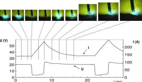
Figure 2.1: Example of electrical transient for current (I) and voltage (U) in short-circuit transfer mode and stages of the metal transfer
The most common means of short-circuit stability assessment is based on the electrical signals (current and voltage) analyses. An ideal arc (welding process totally stable) should have a uniform metal transfer, uniform arc burning and short-circuiting times (in short-circuit transfer case), the same time between the transfer of two consecutive drops (in spray transfer mode), the transfer of one droplet per pulse (in pulsed transfer case), a steady arc length and no spattering. Welding with a stable arc has a lot of advantages, such as economical (avoiding spattering less time is required to clean up the workpiece and torch nozzle) and operational (it is easier monitoring and controlling a stable process).
As the typical electrical signal of a short-circuit transfer can be divided in arc burning and short-circuiting phases along the time axis (Figure 2.2), this two times can be processed and presented in terms of probability distribution. By assessing the probability distribution of the short-circuiting phase, it is possible to determine if there is less or more variation in the time of this phase, therefore if the process is more or less stable. Figure 2.3 shows two probability distributions for two different shielding gases used in short-circuit GMA welding under the same welding parameters. According to Suban and Tusek (2003), the welding
process is more stable for CO2 as shielding gas, since the variation in the respective curve is
smaller than in the Ar/CO2 one. It is important to point out that when Suban and Tusek
mentioned that CO2 promotes more stable conditions, there is no evidence they tried to set
Figure 2.2: Arc burning (tO) and short-circuiting (tKS) phases in short-circuit electrical signals
(SUBAN; TUSEK, 2003)
Figure 2.3: Probability distribution of short-circuiting phase with CO2 and Ar/CO2 as shielding
gases (SUBAN; TUSEK, 2003)
Another way of analysing the stability in short-circuit transfer is by cyclogrammes, which present the arc voltage versus the welding current. Two zones in this graph may be noticed to analyse the stability. The arc period is defined by a high voltage and low current zone, and the short-circuiting period is defined by a low voltage and high current zone. Figure 2.4 presents cyclogrammes for the same welds performed in the Figure 2.3. The
higher stability is found using the CO2 gas, since the cyclogramme occupies a smaller area
remarkable frequency (SUBAN; TUSEK, 2003), otherwise more than one main characteristic frequency appears or it will be impossible to define the main frequencies.
50 45 40 35 30 25 20 15 10 5 0
0 100 200 300 400 500 600
50 45 40 35 30 25 20 15 10 5 0
0 100 200 300 400 500 600 0 100 200 300 400 500 600
50 45 40 35 30 25 20 15 10 5 0
0 100 200 300 400 500 600
50 45 40 35 30 25 20 15 10 5 0
Figure 2.4: Cyclogrammes for short-circuit welding using CO2 and Ar/CO2 as shielding gases
(SUBAN; TUSEK, 2003)
Another means of evaluating process stability in a short-circuit transfer, probalbly the most used, is by using stability indexes. For instance, the stability index (SI) can be defined as a function of the relation between the standard deviation of the weld cycle duration ( ) and the mean value of the weld cycle duration (T), as shown by Eq. (2.1) (CUIURI, 2000). This stability index is ranged from 0 to 1 and increases as the process regularity gets better. By using this method, values of stability index above 0.65 corresponded to good welds using the waveform control method showed in Figure 2.11 and values higher than 0.80 resulted in high quality welds for controlled short-circuit transfer (CUIURI, 2000).
T 1
SI = − (2.1)
The standard deviation of the short-circuiting frequency can be also taken as a stability index (HERMANS; DEN OUDEN, 1999). If the amount of short circuit is required to be
evaluated, it is necessary to measure the mean duration of the short-circuiting period (tc) and
the mean period of the weld cycle (T). Thus, a short-circuit presence index (%SC) may be defined as shown by Eq. (2.2) (MODENESI; AVELAR, 1999).
100 T t %SC c × = (2.2)
et al., 1987, STAVA, 1993) have been tried and accomplished along the last 30 years dealing with current waveform control methods. The common and main objectives of all developments were the improvement of the metal transfer stability (absence of spattering) and better heat input control (penetration control). Almost all the previous and also the recent methods rely on the capability of rapid current turn off that is offered by modern power sources and in monitoring and feedback techniques to control the metallic transfer by an established waveform for the welding current. As a consequence of all these developments (methodologies, software and hardware), there are already some processes for controlled short-circuit transfer available in the market.
One of these techniques is the so-called STT™ (Surface Tension Transfer) (STAVA, 1993). This technique is a modified short-circuit GMAW process that claims to use high-frequency inverter technology with advanced waveform control to produce high quality welds while also significantly reducing spattering and fume generation. It has been advertised that the STT™ technology has the ability to control weld pool heat independently of wire feed speed. This fact enables more control over the weld pool and provides the ability to adjust the heat input to achieve the desired root bead profile (DERUNTZ, 2003). A description about how the STT™ process works is summarized as following (STAVA, 1993, DERUNTZ, 2003, LINCOLN ELECTRIC, 2007a).
A B C D E A
Figure 2.5: STT™ method waveform and metallic transfer stages (after LINCOLN ELECTRIC, 2007a)
The STT™ technique, as the name indicates, relies on the surface tension action to promote the metal transfer, but speeds up the metal transfer using a controlled pinch effect. The STT™ operating (setting) variables are wire feed speed, peak current, background current and tail-out. The wire feed speed controls the deposition rate. According to the STT™ manufacturer (LINCOLN ELECTRIC, 2007b), the peak current controls the arc length, which affects the shape of the weld root face (Figure 2.6), the background current is a “fine” heat control, which affects the back of the bead (Figure 2.7), and the tail-out setting serves as a “coarse” heat control (many open root applications set this control to zero). Figure 2.8 shows a typical weld bead on root run made using the STT™ process.
Figure 2.7: Effect of STT™ background current on the root back (LINCOLN ELECTRIC, 2007b)
Figure 2.8: Typical weld bead on root run made using the STT™ process (LINCOLN ELECTRIC, 2007b)
the current to an even lower level to allow the short circuit and to make sure the arc force does not push the weld pool back (prevents excessive agitation).
A B C D E F G
Current Wave Form
A B C D E F G
Current Wave Form
Figure 2.9: RMD™ method waveform and metallic transfer stages (after MILLER'S NEW, 2007)
Another available technique that relies on current waveform control to improve the short-circuit transfer GMAW process is the CMT™ (Cold Metal Transfer). But this technique manages also the movement of the wire (it feeds or returns the wire as necessary) to enhance the metal transfer dynamics. The CMT™ process works as described in Figure 2.10. In stage A, during the arcing period, the electrode is moved towards the weld pool. When the electrode short-circuits into the weld pool the arc is extinguished and stage B starts dropping the welding current to a low level. In stage C the short-circuit current is kept low and the rearward movement of the wire supports droplet detachment. Thus, in stage D the wire motion is reversed and the process cycle starts again. This method relies almost on the surface tension mechanism to promote the metallic transfer, except for the assistance from the wire returning movement.
A B C D
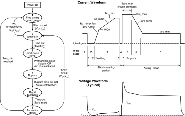
Other techniques have been also developed in research centres around the world (CUIURI, 2000, DEAN, 2003, GONÇALVES e SILVA, 2005, CUIURI; NORRISH, 2006). Recently, researches at University of Wollongong, Australia, developed new approaches to control the short-circuit transfer. One of these approaches (CUIURI, 2000, CUIURI; NORRISH, 2006) also relies on the current rapid turn off capability of the power source. This method considers the welding cycle as a finite number of sequential steps (states), so that the output current can be controlled using different strategies (related to events or pre-determined time limits) depending on the weld state. The method uses two independent current controllers to supply the dynamic main current and the constant background current which is used as “pilot arc” (the welding current in each step is the sum of the main current and the background current).
This method for short-circuit transfer control is described in Figure 2.11. The beginning of a short-circuiting event (weld state 2) is detected by the controller as soon as the voltage
drops bellow an established threshold Vsc (usually 5 V). Thus, the current is rapidly turned off
Power-up 1 Free arcing I=Iarc_min 2 Wetting-in Short circuit
(Vfb<Vsc)
Arc re-established
(Vfb>Varc)
3 Short-circuit ramp Time-out (Twetting) 4 Rupture Premonition circuit triggers OR Arc re-established 5 Rapid burnback
Rupture time-out OR Arc re-established Iarc_ramp Iarc_min Iarc_max Tarc_max (Rapid burnback) Isc_ramp 100A I_backgr Isc_ramp_fast (300 A/ms) Isc_max Weld
state 1 2 3 4 5 6 1
Trupture Twetting
Short-circuiting
period Arcing Period
6 Arc ramp-down Time-out (Tarc_max) Short circuit
(Vfb<Vsc)
Iarc_min reached Current Waveform Vsc Varc 0 Voltage Waveform (Typical)
Figure 2.11: Logic diagram and typical waveform for controlled short-circuit transfer developed at UOW (CUIURI; NORRISH, 2006)
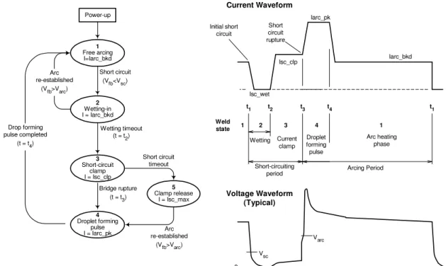
Another innovative technique (DEAN, 2003, CUIURI; NORRISH, 2006), also developed at University of Wollongong, tried a different approach to control the short-circuit transfer. This method relies practically in the surface tension force only to transfer the droplet to the weld pool and can be used with conventional inverter power sources, since it needs only the detection of the rapid voltage increasing on arc ignition and the rapid voltage decreasing at the beginning of the short circuit as references to control the process (it does not need the rapid current turn off capability neither the premonition detection for metal bridge rupture). This method was based on the principle that if a droplet has developed a critical size prior to short circuiting, surface tension forces can be used as the main droplet detachment mechanism. This alternative control technique uses a short-circuit current clamping methodology (the maximum short-circuit current is maintained at levels lower than those that normally would happen when using conventional constant voltage techniques). The advantage of using such methodology is that the short-circuit droplet transfer is allowed to occur predominantly under the influence of surface tension, since the pinch effect is limited by the low level of current applied. This method also minimizes spattering, since the short-circuit current is limited to low values, and it is able to control heat input (penetration control).
short-circuit initiation, the current is reduced to allow the droplet a wetting-in time into the weld pool (weld state 2). After the wetting-in time, the short-circuit current is increased to the clamp level and held at this value until the metal bridge rupture (weld state 3). When the bridge rupture is detected, a current pulse is applied to push the weld pool down and promote the droplet growth, but without detachment (weld sate 4). Then, the current returns to weld state 1, which controls the heat input, and the cycle starts all over again.
Power-up 1 Free arcing I=Iarc_bkd 2 Wetting-in I = Iarc_bkd
Short circuit
(Vfb<Vsc)
Arc re-established
(Vfb>Varc)
3
Short-circuit clamp I = Isc_clp
Short circuit timeout Wetting timeout
(t = t2)
4
Droplet forming pulse I = Iarc_pk
Iarc_bkd Iarc_pk Short circuit rupture Isc_wet Initial short circuit Isc_clp Weld
state 1 2 1
Wetting
Short-circuiting
period Arcing Period
5
Clamp release I = Isc_max Bridge rupture
(t = t3)
Drop forming pulse completed
(t = t4)
Current Waveform Vsc Varc 0 Voltage Waveform (Typical) 3 4
t1 t2 t3 t4 t1
Current clamp Droplet forming pulse Arc heating phase Arc re-established
(Vfb>Varc)
Figure 2.12: Logic diagram and typical waveform for another controlled short-circuit method developed at UOW (DEAN, 2003)
Figure 2.13: Root run performed using a controlled short-circuit process in a mechanized approach (YAPP; BLACKMAN, 2003)
2.2 Tandem GMAW
As a result of the continuous need for improvements in productivity (high welding travel speeds and/or high metal deposition rates) and due to the advanced power electronics available, new welding processes have been developed and some “reinvented” (reformulated for new applications) during the last years. One of these “new” processes is the Tandem/Twin GMAW. Ueyama et al. (2004) cite that the use of Tandem/Twin wires remote to the 1970’s years, but only within the last decade the process became really feasible.
Previous to discussing further more about this process, it is important to define tandem GMAW, distinguish it from Twin GMAW and introduce the basis of pulsed GMAW (the usual transfer mode for tandem GMAW).
2.2.1 Tandem GMAW versus Twin GMAW
Sync Sync Sync
Figure 2.14: Typical system for tandem GMAW using a single torch
Figure 2.15: Experimental torch for tandem GMAW designed at University of Wollongong (CUIURI, 2000)
Figure 2.16: Typical system for twin GMAW
Although this general difference mentioned between the tandem and twin GMAW versions, in pratical applications the use of such definitions are not a consensus. For this reason, in this work the tandem GMAW process will be considered as two GMAW wires connected to different electrical potentials (power sources) and feeding sequentially into the same weld pool.
2.2.2 Pulsed GMAW
pulsed GMAW to be applied on thin materials, control distortions and run with low wire feed rates.
However, it is not so easy to set the parameters to obtain one droplet per pulse, since it depends on the welding condition (base material, electrode material and diameter, shielding gas, etc.)(PALANI; MURUGAN, 2006). Optimum pulsed transfer conditions are obtained by
limiting the pulse duration tp and the relationship Ipntp=D is often used to define the ideal one
droplet per pulse condition. Here Ip is the pulse current amplitude (well above the spray
transition current), n is a process dependent factor (usually between 1.2 and 2) and D is the detachment factor (related to the wire) (PALANI; MURUGAN, 2006; RICHARDSON et al., 2006). Although the relationship mentioned above is widespread, there is a study pointing out another relationship to achieve one droplet per pulse in welding of aluminium (VILARINHO; SCOTTI, 2000).
Norrish (1992) presents an approach to select the operation parameters for pulsed welding. Firstly the pulse current and duration must be selected from adequate droplet detachment charts (pulse current versus pulse duration map for one droplet per pulse). The second step is the specification of a suitable mean current for the application (considering the material, thickness, etc.). After that it is necessary to determine the required wire feed rate from a burn-off chart (wire feed rate versus mean current) for the wire of choice. Thus the required pulse frequency must be selected from a wire feed rate versus frequency chart.
The final steps are the selection of tb and Ib based on equations relating the parameters of
the pulsed wave.
The general influence of the pulse parameters can be summarized as the pulse current and time being responsible for the metal transfer control while the background current and time being in charge of the heat input control. According to Stanzel (2007) it is alleged that pulsed GMAW is able to:
• Reduce spattering to nearly non-existent levels;
• Minimize distortion, compared to spray transfer mode;
• Create weld beads with good appearance;
• Weld thin metals;
• Allow all-position welding;
• Increase travel speeds (over short-circuit transfer).
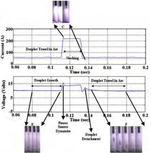
way to do that has been through arc luminescence analysis (MIRANDA et al., 2004). Jilong (1982) and Praveen; Kang; Yarlagadda (2006) in their analyses of metal transfer under pulsed conditions also found indications of one droplet per pulse circumstances. They identified visible marks (small peaks overwritten) in the voltage signals when the droplet is detached from the wire (Figure 2.17). The identification of these small voltage peaks is an alternative for rapid indication of one droplet per pulse state. This method, however, works with analogical power sources only.
Figure 2.17: GMAW images synchronized with arc current and voltage waveform for one droplet per pulse (PRAVEEN et al., 2006)
always a challenge. Experiments conducted at The Edison Welding Institute (EWI) showed that AC GMAW was able to perform root runs of good quality on pipes. A root run welding without backing at travel speeds of 1.5 m/min was produced (Figure 2.18) (YAPP; BLACKMAN, 2003).
Figure 2.18: Root run with AC GMAW (YAPP; BLACKMAN, 2003)
2.2.3 Tandem GMAW advantages and limitations
Due to the tandem process versatility (independent settings for each arc), it has found more acceptance among welding costumers than the twin GMAW version. The main advantage claimed to tandem GMAW is the enhancement in productivity. With tandem GMAW is possible to achieve travel speeds in excess of 5 m/min (LINCOLN ELECTRIC, 2007c), but common values stay around 3 m/min (UEYAMA et al., 2005). This high velocity characteristic leads this process to automated applications and it is believed to be due to the high level of current used and to the formation of an elongated weld pool. As the base metal is exposed to the molten pool for a longer period of time, the welding travel speed can be increased to achieve a specified penetration, for instance. With an extended weld pool the arc force can be also distributed over a larger area of molten metal, which may result in less instability.
more time and more area to escape, which reduces porosity (MICHIE et al., 1999). This information can, however, be doubtful, since there is also more area for the gases to get into the weld pool.
Despite these advantages, as parameters for two wires must be set, the tandem GMAW process tends to demand more training to operators than the traditional single wire GMAW. Regarding the high current levels employed, a close look to health and safety concerns is demanded as a general rule as well (higher shade number and fume extraction units should be considered, for instance). But probably the main disadvantages of the process are the initial cost and the tendency for interaction (interference) between the arcs. The initial cost can be rapidly supplanted by the high productivity achieved and a tendency of price dropping is expected as the diversity of equipments dedicated to this process has increased. In relation to the interaction between the arcs, this issue has been the target of a number of studies conducted by welding researches. Despite its rising importance for the industry, tandem GMAW process remains less well known than single wire GMAW, and information about it is more focused on economics and there are not many comparisons to single wire GMAW.
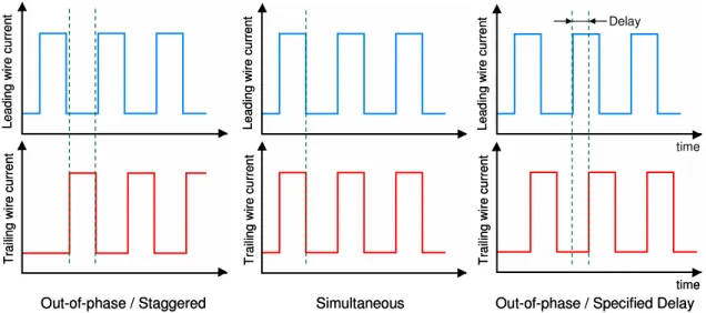
Generally, it has been claimed that the most common way of avoiding the interaction between the arcs and, therefore, stabilizing the metal transfer in tandem GMAW, has been through out-of-phase current pulsing. As the process uses two power sources, one is set as the master (responsible for command) and the other as the slave one (commanded). The power sources are synchronized in such way that while the current provided by the master power source is in the pulse time, the current supplied by the slave one is in the base time (the pulsing frequency for both electrodes is the same). It has been considered that by using such a method the magnetic interaction between the arcs can be minimized (UEYAMA et al., 2004), and that is the reason for less instability in out-of-phase welding. However, it has been found that this is not true for high mean current levels (SCOTTI et al., 2006). The authors showed that there is no evidence that out-of-phase current pulses can impose any reduction in the attraction of the arcs and droplets at high current levels. Although such work stated that there is no need for advanced power sources (out-of-phase capability) to reach sound welds, it confirms the importance of out-of-phase pulsing method to minimize arc interaction when the levels of current are not so high.
stabilize the process and avoid arc interruptions, allowing high welding travel speeds to be reached (UEYAMA et al., 2004).
Le ad in g w ire c ur re nt T ra ili ng w ire c ur re nt
Out-of-phase / Staggered
Le ad in g w ire c ur re nt T ra ili ng w ire c ur re nt
Out-of-phase / Staggered
Le ad ing w ire cu rr ent T raili ng w ire c ur re nt Simultaneous Le ad ing w ire cu rr ent T raili ng w ire c ur re nt Simultaneous Lea di ng w ire c ur rent T raili ng w ire cur re nt time time
Out-of-phase / Specified Delay
Delay Lea di ng w ire c ur rent T raili ng w ire cur re nt time time
Out-of-phase / Specified Delay
Delay
Figure 2.19: Different kinds of timing pulse controls applied in tandem GMAW
2.2.4 Parameters general influence
It has been mentioned that in pulsed tandem GMAW the leading arc is responsible to provide penetration while the trailing arc controls bead appearance. The functions of the leading electrode are to produce sufficient amount of molten metal with high currents and assure penetration in the base metal by its strong arc force and the functions of the trailing electrode are to prevent humping beads (maintaining the molten pool shape by its arc force and surface tension of the molten metal) and prevent undercut at the toe of the weld by filling molten metal (OHNAWA, 2003).
speed to be reached. This distance has found to be between 9 and 12 mm (MICHIE et al., 1999).
As the tandem process uses the same gas blends as the single wire GMAW version,
the gas effects are expect to remain the same. The CO2 effect of increasing the sidewall
penetration and also the O2 effect of decreasing the weld pool surface tension can be
important for root run welding, since they can influence to build up the equilibrium of the weld pool in order to avoid burn-through and humping bead, for instance.
2.2.5 Difficulties in operating with pulsed mode in low mean current levels
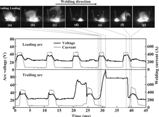
Besides arc interference (attraction), which is well mentioned in the literature, problems of arc interruption may also arise in tandem pulsed GMAW when operating in low levels of mean current (UEYAMA et al., 2005). In contrast with the arc attraction phenomenon, the arc interruption in these circumstances is not commonly discussed in the literature. Ueyama et al. (2005) investigated the effect of some parameters on the number of arc interruptions
(Figure 2.20) in tandem pulsed GMAW. The results demonstrated that these interruptions are
related to abnormal arc voltages and occur frequently when one arc is in the pulse current and the other one is in the base current. They were verified under conditions with an inter-wire distance of around 10 mm (Figure 2.21) and with CO2 presence in the shielding gas
exceeding 10% (Figure 2.22). The number of arc interruptions was remarkably higher in the trailing wire than in the leading one. Taking these results into consideration, a short inter-wire distance and a low percentage of CO2 should be used to minimize the number of
interruptions, but the same authors (UEYAMA et al., 2005) showed that inter-wire distances between 9 and 12 mm and a shielding gas rich in CO2 (20%) produced the highest travel
Figure 2.20: Typical current and voltage waveforms when an arc interruption occurs in tandem GMAW (UEYAMA et al., 2005)
Figure 2.22: Effect of CO2 mixture ratio on abnormal arc voltage and arc interruption
occurrences in tandem GMAW (UEYAMA et al., 2005)
Figure 2.23: Effect of the trailing wire base current level on the number of abnormal arc voltage and arc interruption occurrences in the trailing wire in tandem GMAW (UEYAMA et
al., 2006)
Figure 2.24: Model for arc displacements in tandem GMAW (UEYAMA et al., 2005)
Ueyama et al. (2006) also identified that when the pulse current is simultaneously output to both wires (in-phase pulsed welding) the incidence of abnormal arc voltage and arc interruptions were low. Figure 2.25 shows a comparison between the incidence of arc interruption in the trailing arc for in-phase (simultaneous-pulse control) and out-of-phase (staggered-pulse control) welding with an inter-wire distance of 10 mm and 20% or 25% of CO2 in the Argon based shielding gas. The decrease in the number of arc interruptions was
Figure 2.25: Arc interruption occurrences in the trailing arc for in-phase and out-of-phase tandem pulsed GMAW using different CO2 percentage in the shielding gas (UEYAMA et al.,
2006)
Based on the importance of the arc stiffness to avoid arc interruptions, a possible
measure to avoid this inconvenience would be by forcing early output of the succeeding
Figure 2.26: Method of small delay to avoid arc interruptions in tandem GMAW (above) and delay value influence on abnormal voltage and arc interruption occurrences in the trailing
wire (below) (UEYAMA et al., 2006)
2.3 Laser - GMAW Hybrid Welding
Hybrid welding processes using Laser and arc processes have been developed for 30 years and their application has recently spread to the industry, mainly to the automotive sector. During the first ten years of development, the low Laser power available and the high cost of Laser equipments were, along with the lack of knowledge about the hybrid processes, certainly the main limiting factors. After 1990, the Laser - arc welding experienced a boom in research and development. Hybrid versions like Laser - TIG, Laser - Plasma and Laser - GMAW were highly developed. Although a variety of Laser - arc welding processes has been developed over the last three decades, several questions are still not answered.
of Laser employed in the hybrid approach proposed. More details of Laser theory and application can be found in specialized literature. As the way the Laser beam is combined with tandem GMAW in this work is an innovation, a general discussion on Laser - GMAW is also presented as a basis to explore the new hybrid welding approach.
2.3.1 Laser Beam Welding
The early work with Lasers dates to the 60’s. Following the advances made throughout the last decades, Laser systems have become more reliable and cheaper and their use has reached the most diverse areas, such as medical, military, electronics, communications, sensors and instrumentation, etc. The Laser use has become quite common in manufacturing as well, where it can be used, for instance, for surface treatment, cladding, cutting and welding. Lasers can be used for welding independently (Laser Beam Welding) or combined with other process (usually arc welding process) in the so-called hybrid welding.
The advantages and specially the limitations of Laser welding tend to be linked to the type of Laser used. However, general qualities and problems can be pointed. The primary advantage of Laser beam welding is the capacity of energy concentration. As the Laser beam is usually concentrated in a very small area, a high density of energy is achieved (increased travel speeds or deep and narrow welds). This characteristic leads to several other advantages. According to Booth (2004), due to the narrow deep penetration weld produced, Laser welding offers several advantages over other welding processes such as high joining rates, low consumable costs, high reproducibility, low manning levels, low levels of distortion (precision in assembly and reduction of rectification work).
Despite these advantages, the process faces two main limitations: high cost of equipments (including beam delivery and focusing systems) and low tolerance to joint misalignment and gaps. Since Laser beam welding produces narrow welds at high speeds, there is also a risk of welding defects such as lack of fusion, solidification cracks and porosity. Moreover, LBW (Laser Beam Welding) also faces difficulties when it comes to weld highly reflective materials such as aluminium and copper. During LBW the interaction of Laser beam, metal vapour and shielding gas produces induced plasma, which can reduce the process efficiency, since it blocks the beam (DAWES, 1992).
whilst keeping the overall spot size sufficiently small to maintain the welding at reasonable speeds. Elongation of the weld pool perpendicular to the direction of welding improves the capacity for gap bridging and, hence, enables fit-up tolerances to be relaxed. Analogously, elongation of the weld pool parallel to the direction of welding assists in the escape of gas bubbles and metal vapour. The technique thus reduces porosity. Elongation of the weld pool can be achieved using two Lasers with focused spots very close to each other or using a single Laser source with a beam splitter to generate two focused spots at predefined locations. Additionally, the Laser energy is not necessarily divided equally between the two spots; the energy can be apportioned between the two spots in any appropriate ratio. This is particularly useful when making butt welds between two sheets of different thickness. By using two Laser spots aligned perpendicularly to the direction of welding the majority of the energy can be directed to the Laser spot on the thicker plate, thus improving joint quality.
2.3.2 Type of Lasers used for welding
Almost all Laser systems commercially available for welding are CO2 and Nd:YAG
Laser sources. Although CO2 and Nd:YAG Lasers are the most predominant systems for
welding, they have been hampered by their size, complexity, high cost and their low efficiency. New systems such as high power diode Lasers have become recently available in
the market as well. This kind of Laser has become even competitive with traditional CO2 and
Nd:YAG due to improved reliability, good life time and declining cost of diodes (STAUFER, 2007).
Diode Lasers have several advantages over CO2 and Nd:YAG Lasers. They are
extremely efficient, with 35% of the pumped energy being turned into output beam power (KENNEDY; BYRNE, 2003). Diode Lasers are also reasonably compact in size, their output beam can be delivered by optic fibre and they have nowadays a capital cost equivalent to
CO2 Lasers (KENNEDY; BYRNE, 2003).
2.3.3 Laser - arc welding
Although it is possible to use the Laser beam as a unique source of heat to promote union of materials, the combination of the beam provided by a Laser system with a ‘conventional’ welding process has become largely studied and applied in the so-called hybrid welding. There have been described systems for hybrid welding combining Laser with GTAW (HU; DEN OUDEN, 2005), with PAW (PAGE et al., 2002, SWANSON et al., 2007), with GMAW (KIM et al., 2006, MULIMA et al., 2006) and even with SAW (TUSEK; SUBAN, 1999).
Regardless of the process of choice to be combined with the Laser, the general and eventual result is the increase in the effectiveness of the welding. It is well known that LBW is distinct for providing high power density, deep penetration, high welding speed, low distortion and precision. However, because of the small Laser beam spot, LBW shows poor gap bridge ability and precision in joint preparation is always a requirement. On the other hand, arc welding processes have relatively lower power density and produce wider weld beads, delivering good bridge ability for joint gaps and large tolerances for joint preparation. The combination of LBW and arc welding tends to enhance the advantages and compensate the limitations found in each process. The final result is an increase in the weld penetration depth, width and welding travel speed. Despite the lack of information on the use of Laser with tandem GMAW, a number of studies on hybrid welding with Laser and single wire
GMAW (Figure 2.27) have been published, most of them using CO2 or Nd:YAG Lasers.
Work-piece GMAW torch
Weld
Laser head
Work-piece GMAW torch
Weld
Laser head
Figure 2.27: Typical hybrid Laser - GMAW arrangement (Booth, 2004)
Figure 2.29: Commercial head devised for Laser - GMAW hybrid process (Fronius, 2008a)
According to Booth (2004), if compared with the use of Laser power alone, hybrid Laser - arc welding offers:
• Increased travel speed (2 times) or increased penetration (1.3 times) (Figure 2.30);
• Improved tolerance to fit-up gap;
• Ability to add filler material to improve weld metal microstructure, joint quality and
joint properties;
• Potentially improved energy coupling;
Figure 2.30: Comparison of welding speed and penetration for single and hybrid processes (steel) (Booth, 2004)
However, Booth also points some drawbacks, which include increased complexity, the need to define additional welding parameters and the requirement to establish the process parameters anew as these cannot be determined simply from the optimum procedures for the two separate processes. Nevertheless, he says that the hybrid Laser - arc welding is now a production process in both the automotive and shipbuilding industries and has been shown to be a candidate process for girth welding of gas transmission pipelines. The high cost added by the Laser part of the process is certainly another great limitation and the spatters that may be generated during the hybrid welding process, mainly due to the GMAW process, is likely to damage optical components in use with the Laser.
Tusek and Suban (1999) cite that the main advantage of the use of both heat sources is the more efficient use of the energy supplied. With certain parameters, the quantity of molten material increases by 100% compared with the sum of the individual quantities of molten material in the individual processes. The synergic action of the Laser beam and welding arc shows that the Laser beam in the welding arc, when current intensities are low, affects ionisation, reduces arc resistance, and increases the number of carriers of electrical current. However, according to Tusek and Suban (1999), it is not understood which property of the Laser beam contributes the most to the higher ionisation; whether it is the higher concentration of heat energy alone or to some extension the presence of electromagnetic waves with short wavelength.
combination with a GTAW arc. It was found that the stabilising effect can be explained in terms of two phenomena: the absorption of Laser energy by the arc plasma and the change of the arc plasma composition caused by strong evaporation of workpiece material. Both phenomena lead to a reduction of the effective ionisation potential of the plasma and thus provide a more conductive, stable plasma channel for arc root and column that overcomes disturbance by external forces.
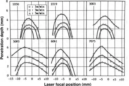
Qin; Lei; Lin (2007) studied the effects of hybrid Nd:YAG Laser - pulsed GMA welding parameters on the weld shape using bead-on-plate tests. The results indicated that the Laser energy mainly decides the weld penetration and that the weld width depends on the arc process for a given welding speed. The distance between the Laser spot and the arc, and the location of the Laser focus also had some effects on the hybrid weld appearance. The addition of Laser energy into pulsed GMAW can greatly increase not only the weld penetration, but also the welding speed, and it can also improve the weld appearance for low welding currents.
Kim et al. (2006) carried out experiments with Laser - GMAW and found that the heat input delivered to the plate is dependent on the nature of the leading heat source (Laser or GMAW) and also the joint condition used in the hybrid set-up. Synergic effects of the two heat sources are maximised when the Laser beam is located between the arc centre and the impact point of the molten droplets within the weld pool. The final bead shape in hybrid welding is influenced by the volume of the molten pool before the impingement of the Laser beam. That is, a critical depth of molten material needs to be formed before being irradiated by the Laser beam in order to maximise the coupling effects of the respective heat inputs. The weld bead shape was also found to be dependant on other features of the welding process such as joint gap condition, leading heat source and preheating effects.
Despite the fact LBW is largely used in combination with pulsed GMAW, Mulima et al. (2006) presented the first trials using Laser (Diode) combined with GMAW in a controlled short-circuit transfer mode. The objective was to verify the possibility of improving the joint completion rate and produce deep penetration welds at higher travel speeds. The controlled short-circuit transfer is well known for the capacity of delivering a controlled heat to the workpiece and absence of spatters. It was shown that the welding travel speed is significantly increased or deep penetration achieved, both known as limitations of the controlled short-circuit transfer process.
girth welds in these steels with significantly fewer welding passes than are currently required for arc-welded pipelines, reducing the joint completion time. The high penetration possible with hybrid Laser - arc process prevents the problems associated with the rapid cooling and solidification crack susceptibility of Laser welding, while maintaining the advantages of deep penetration depth or fast travel speed from high-power Laser welding.
2.3.4 Welding speed in Laser - arc hybrid welding
The need for high welding travel speeds, keeping high deposition rates and penetration capabilities, has driven the search for new welding processes or improvements in the existent ones. The hybrid welding with Laser and GMAW seems to fill this requirement very well. A welding travel speed increase of up to 90 % relative to the welding with Laser and cold wire has been reported (NIELSEN et al., 2002).
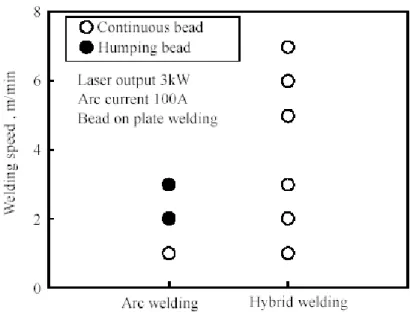
Another study shows an increase in welding travel speed from 1 m/min to 2.6 m/min when Laser with cold wire is replaced by Laser - GMAW (DILTHEY; WIECHEMANN, 1999). The key for the high welding speed capability of Laser - GMAW seems to be the ability to avoid humping formation (BAGGER; OLSEN, 2005). The formation of humping is typical to practically all the welding process when high welding travel speeds are attempted (SCOTTI, 1991, REIS, 2005). The hybrid process has been used with the Laser beam defocused and at a short distance in front of the leading edge of the GMAW weld pool by Bagger and Olsen (2005). The beam power and spot size were varied in tests and, given a GMAW process condition, bead humping formation was suppressed by Laser heat input of sufficient power density (relationship between power intensity and beam spot area). Comparison of the tow angles of humped and non-humped weld beads suggested that capillary instability was a factor likely to contribute to weld bead hump formation. Cho and Farson (2007) also showed that the use of a Laser beam in front of the GMAW weld pool prevents the formation of humping. According to their work the humping is avoided by applying a Laser beam with intensity and spot size sufficient to provide a bead width large enough to prevent capillary instability.
Figure 2.31: Welding speed limit for arc welding and hybrid welding (ONO et al., 2002)
2.3.5 Gap tolerance (bridgeability) in Laser - arc welding
The gap tolerance of a welding process can be defined as the ability the process has to join (bridge) the molten sides of a joint and keep this union stable until solidification takes place. This ability is often measured through the maximum gap allowed for a determined welding package (process and parameters). Figure 2.32 gives an idea on how the welding process determines the gap tolerance.
Positional tolerance of power source Gap tolerance
Laser (CO2, YAG) HLDL Plasma TIG MIG/MAG
1,25 1,00 0,75 0,50 0,25 0,00
A
dm
is
si
bl
e
to
le
ra
nc
e
in
m
m
Figure 2.32: Gap bridgeability and positioning requirements for different welding processes (HLDL: a kind of LBW with Diode Laser) (KUTSUNA; LIU, 2007)
which works as a mass of material to fill up the empty space left by the gap. In order to improve the gap tolerance of Laser welding, filler wire, including cold wire (JOKINEN; KARHU; KUJANPAA, 2003, SUN; KUO, 1999) and hot wire (XIAO et al., 2004), has been attempted. The wire feed speed seems to be a limitation of these approaches since they rely on part of the Laser beam energy to melt the wire. This may have been one of the forces driving investments in Laser - GMAW. Laser - GMAW can feed more wire to the molten pool and the gap bridging ability can be improved. Numerous studies have been conducted on this topic.
Figure 2.33 shows the correlation between maximum welding speed and gap width in CO2
Laser - GMAW.
Laser
2250 W CO2 Laser 9 kW MIG
2.13 mm CMn 250
MIG Hybrid
0 0.1 0.2 0.3 0.4 0.5 0.6 0.7 Gap width [mm]
M ax im u m w el d in g s p ee d [m /m in ] 5 4.5 4 3.5 3 2.5 2 1.5 1 0.5 0
Figure 2.33: Maximum welding speeds obtainable at various gap distances in butt welding using Laser, GMAW and Hybrid processes (BAGGER, 2003)
Figure 2.34: Gap tolerance in Laser welding of lap joints (ONO et al., 2002)
Figure 2.35: Gap tolerance in Laser - GMAW of lap joints (ONO et al., 2002)
2.3.6 Reduction of porosity formation
hybrid welding with an arc current at 100 A. Probably this happened because in the GTAW fluid flow changes from laminar to turbulent at around 100 A. Figures 2.37 and 2.38 illustrate how the flow pattern in the weld pool can be dependent on the welding process used. According to the model, in the case of Laser welding the molten metal tends to rotate at the bottom of the molten pool with the gas bubbles formed following along and eventually getting trapped in the weld bead. In contrast, in hybrid welding the molten metal flows from the surface to the bottom of the molten pool and back. In this case, the bubbles formed at the bottom of the pool flow along with the molten metal and escape.
Figure 2.36: X-ray inspection images showing porosity formation tendency in Laser and in hybrid welding (NAITO; MITSUTANI; KATAYAMA, 2006)
Figure 2.38: X-ray transmission observation in hybrid welding (NAITO; MITSUTANI; KATAYAMA, 2006)
2.3.7 Effects of hybrid welding parameters on the weld bead
The analysis of the influence of the welding parameters in hybrid welding is not as simple as joining the influence of the processes individually. There is a synergic effect present in the hybrid process, which plays an important effect. The following items present an overview on the effect of some parameters on the weld profile and quality.
Laser - arc arrangement
One of the first questions to emerge when dealing with hybrid welding is about which process should lead; whether the Laser or the arc process. There have been a number of researchers studying the Laser hybrid welding. Some of them tried the Laser as the leading process (ENGSTROM et al., 2001, KUTSUNA; CHEN, 2002, UCHIUMI et al., 2004) and some others the arc as the leading process (NAITO et al., 2004, ARIAS et al., 2005, LIU; KUTSUNA, 2005).
By studying the influence of the process arrangement on the bead shape Abe et al. (1996) showed that the fact of placing the Laser first (leading the process) improved the bead shape in relation to the situation with the arc process first. Nielsen et al. (2002) showed that the penetration was increased by 10% if the GMAW source is placed after the Laser.
However, in another study, Beyer et al. (1994) used CO2 Laser - GMAW to show that the
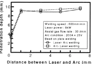
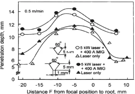
Figure 2.39: Influence of the process arrangement and distance between the processes on penetration depth (BEYER et al., 1994)
Figure 2.40: Penetration in MIG, MIG-YAG and YAG-MIG at different levels of arc current (Naito et al., 2002)
Distance between the Laser beam and the arc