F
ACULDADE DEE
NGENHARIA DAU
NIVERSIDADE DOP
ORTOColor Space Conversion in Hardware
for Multimedia Applications
Carlos Rodrigues
Mestrado Integrado em Engenharia Eletrotécnica e de Computadores Supervisor FEUP: Prof. João Canas Ferreira
Supervisor Synopsys: Eng. João Gonçalves
Resumo
Em aplicações multimédia de transmissão de vídeo existe por vezes a necessidade de ter em conta as caraterísticas do recetor, por exemplo negociar os formatos de espaços de cor ou de frequências de vídeo antes de iniciar a transmissão. Consequentemente, em situações em que o conteúdo não está disponível num espaço de cor suportado pelo recetor existe a necessidade de converter esse conteúdo para um espaço que seja suportado, para possibilitar a transmissão.
Esta tese desenvolve um módulo de hardware capaz de converter streams de vídeo entre difer-entes espaços de cor em tempo real. Este módulo é sintetizável para frequências de 600 MHz em tecnologias de 40 nm. Suporta conversões de formatos RGB e YCrCb 4:4:4 e 4:2:2 entre os espaços de cor: ITU-R BT.601, ITU-R BT.709, ITU-R BT.2020, sRGB, opRGB, bg-sRGB, xvYCC601 e xvYCC709. Também suporta repetição de pixel e formatos de vídeo 3D.
O módulo desenvolvido implementa todos as etapas necessárias para converter corretamente entre espaços de cor, desde as conversões matriciais RGB para YCrCB e RGB para RGB à cod-ificação e descodcod-ificação gamma. As opções de reamostragem dos canais de crominância são implementados por filtros de decimadores e interpoladores em duas configurações, de 30ae 18a ordem, entre as quais a primeira é compatível com os requisitos de filtros definidos pelos standards ITU-R BT.601 e ITU-R BT.709.
Abstract
In multimedia applications of video transmission there is usually the need to account for the re-ceiver’s capabilities, for example negotiating color formats and video frequencies before initiating the transmission. Consequently, in situations where the content is not available in a color space supported by the receiver, there is the need to convert that content to one color space that is sup-ported.
This thesis develops an hardware module that is capable of performing real-time color space conversion of video streams. This module is synthesizable for 600 MHz frequencies in 40 nm technologies. It supports the RGB and YCrCb 4:4:4 and 4:2:2 conversions between: ITU-R BT.601, ITU-R BT.709, ITU-R BT.2020, sRGB, opRGB, bg-sRGB, xvYCC601 and xvYCC709 color spaces. This module is also compatible with pixel-repetition and 3D video formats.
The developed module implements all the steps required to properly convert between color spaces, from RGB to YCrCb and RGB to RGB conversion matrices to gamma encoding and de-coding. The chroma resampling capability is implemented by chroma upsampling and downsam-pling filters, available in a 30 taps and a 18 taps configurations, from which the first is compliant with the templates defined in the ITU-R BT.601 and ITU-R BT.709 standards.
Acknowledgments
I would like to thank my supervisors at Synopsys and FEUP, Eng. João Gonçalves and Prof. João Canas Ferreira, for all the support and help provided during the development of this thesis.
I would also like to thank the team at Synopsys which welcomed me so well and helped me during the development of this thesis.
I would like to thank my family and my girlfriend for the all the support.
To my friends and Tuna de Engenharia which provided me with so enriching experiences and friendships during my student life.
Carlos Rodrigues
“Color is my day-long obsession, joy and torment.”
Claude Monet
Contents
1 Introduction 1
1.1 Context . . . 1
1.2 Objectives and Contributions . . . 2
1.3 Structure of the Document . . . 3
2 Background Information 5 2.1 An Introduction to Colorimetry . . . 5
2.2 Color Spaces . . . 5
2.3 Gamma correction . . . 7
2.4 Luma/Color-difference encoding . . . 8
2.5 Video Formats and Structure . . . 9
2.6 Color Space’s Standards . . . 12
2.6.1 ITU-R BT. 601 . . . 12 2.6.2 ITU-R BT. 709 . . . 12 2.6.3 ITU-R BT. 2020 . . . 13 2.6.4 IEC 61966-2-1/Amendment 1 . . . 14 2.6.5 IEC 61966-2-5 . . . 14 2.6.6 IEC 61966-2-4 . . . 15 2.6.7 Gamut Comparison . . . 15 2.6.8 Summary . . . 15
3 State of the Art of Architectures for Color Space Conversion 17 3.1 Color Space Conversion . . . 17
3.2 Chroma Subsampling . . . 22
3.3 Summary . . . 26
4 Architecture Design 29 4.1 Introduction . . . 29
4.2 Top Level Interface . . . 29
4.3 Implementation Strategy . . . 30
4.4 RGB to RGB Converter . . . 33
4.5 R’G’B’-Y’Cr’Cb’ Converters . . . 34
4.6 Gamma Encoder and Decoder . . . 36
4.7 Chroma Resampling Filters . . . 38
4.8 Control Unit and Register Bank . . . 41
4.9 Verification Environment . . . 44
4.10 Verification Plan . . . 45
5.3 R’G’B’-Y’Cr’Cb’ Converters . . . 54
5.4 Gamma Encoder and Decoder . . . 55
5.5 Chroma Resampling Filters . . . 55
5.6 Control Unit and Register Bank . . . 64
5.7 Top Level . . . 64
5.8 Verification Results . . . 65
5.9 Results . . . 68
6 Conclusions and Future Work 77
List of Figures
2.1 Color matching experiment (from [1]). . . 6
2.2 CIE 1931 chromaticity diagram with sRGB color space represented (from [2]). . 7
2.3 Generic gamma correction transfer function (from [3]). . . 8
2.4 Color conversion process. . . 10
2.5 Video frame structure. . . 11
3.1 Direct implementation of conversion operation from [4]. . . 20
3.2 Systolic architecture (from [5]). . . 21
3.3 Conversion matrix (from [5]). . . 21
3.4 Distributed arithmetic architecture (from [5]). . . 22
3.5 Comparison of results (from [5]). . . 22
3.6 Chroma subsampling schemes from [6]. . . 23
3.7 Template for Cr and Cb filtering (from [7]) . . . 24
3.8 Specification for filter 4:4:4 to 4:2:2 color-difference signals (from [8]). . . 25
3.9 Proposed filters comparison. . . 28
4.1 Top level interface . . . 30
4.2 System architecture. Table4.1relates the top-level signal’s naming of figure4.1 with the higher level description of this figure. . . 31
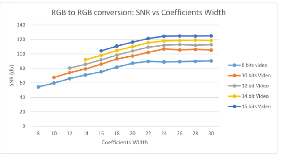
4.3 Comparison of the SNR obtained for the RGB to RGB conversion for different coefficients widths for each video bit width. . . 35
4.4 Comparison of the probability of error obtained for the RGB to RGB conversion for different coefficients widths for each video bit width. . . 35
4.5 Architectures of the upsampling and downsampling filters. . . 39
4.6 Magnitude frequency response of the 30thand 18th order filters, against the tem-plate (dotted line). At the edge of the stopband 0.5πrads/sample or 0.25 fs the 30 taps and 18 taps filter magnitude responses are approx. -6 dB, being compliant with the template requirement of at least -6 dB. . . 42
4.7 Detail of the magnitude frequency response of the 30thand 18thorder filters in the passband. The standards templates require the passband (frequencies up to 0.2 fs or 0.4πrads/sample) attenuation to be |A| ≤ |0.05|dB. . . 43
4.8 Verification Environment architecture. . . 46
5.1 Comparison of the estimated area and power consumption of the RGB to RGB module with the number of pipeline stages implemented. . . 53
5.2 Comparison of the estimated area and power consumption of the RGB to YCC module with the number of pipeline stages implemented. . . 56
5.3 Comparison of the estimated area and power consumption of the YCrCb to RGB module with the number of pipeline stages implemented. . . 57
module with the number of pipeline stages implemented. . . 59
5.6 Downsampling filter structure. . . 60
5.7 Upsampling filters structure. . . 61
5.8 Register bank interface transfer diagrams. . . 64
5.9 Coverage results obtained from simulation. . . 65
5.10 Verification of the downsampling filters impulse response. . . 66
5.11 Verification of the upsampling filters impulse response. . . 67
5.12 RGB Rec.2020 non-constant luminance output image, input image read as RGB sRGB image. . . 71
5.13 Comparison of theY’Cr’Cb’ 4:4:4 Rec.601 image obtained using the developed module and the Matlab rgb2ycbcr function. . . 72
5.14 Comparison of Y’Cr’Cb 4:2:2 Rec.601 525-lines output images obtained with the two filter configuration, input image read as RGB sRGB image. . . 73
5.15 Comparison of Y’Cr’Cb 4:2:2 Rec.601 525-lines output images obtained with the two filter configuration and then converted to RGB using Matlab ycbcr2rgb func-tion to improve the legibility of the text. Input image read as RGB sRGB image. . 74
5.16 Comparison of the RGB 4:4:4 mandrill’s images after being downsampled to YCC 4:2:2 and then upsampled to back to RGB 4:4:4, considering the Rec.601 525-lines color space. . . 75
List of Tables
2.1 Comparison of the gamut of the different color spaces, as a percentage of the visible colors gamut (from [9]) . . . 15
3.1 Comparison on the performances announced in the proposals found . . . 23
4.1 Top level interface signal description. . . 32
4.2 Comparison of the variation of the RGB to RGB conversion coefficients width and SNR and probability of error measured for 16 bit width video. . . 34
4.3 Comparison on the length of the segmentation segments and the size of the LUTs required. . . 38
4.4 Comparison of the hardware costs of 30thand 18thorder filters. . . 41
4.5 Verification Plan . . . 47
5.1 Synthesis results of the constant-luminance R’G’B’-Y’Cr’Cb’ converters modules. 55
5.2 Synthesis results of the 30thand 18thorder resampling filters. . . 63
5.3 Top-level synthesis results of the 30thand 18thorder filters configurations. . . 68
Abbreviations and Symbols
3D Tri-dimensional
BBC British Broadcasting Corporation CAD Computer-Aided Design
CEA Consumer Electronics Association CIE Comission International de l’Éclairage CRT Cathode Ray Tube
DUT Device Under Test FIR Finite Impulse Response
FPGA Field-Programmable Gate Array HDTV High Definition Television
IEC International Electrotechnical Commission IP Semiconductor Intellectual Property Core ITU International Telecommunication Union
ITU-R BT. ITU Radiocommunication Sector Broadcasting service (television) JPEG Joint Photographic Experts Group
LCD Liquid Crystal Display LSB Least Significant Bit MSB Most Significant Bit
NTSC National Television System Committee OVM Open Verification Methodology PAL Phase Alternating Line
R&D Research and Development
RGB Signal Composed by Red, Green and Blue Components Rec. ITU-R BT. Recommendation
SDTV Standard Definition Television UHDTV Ultra High Definition Television UVM Universal Verification Methodology VHS Video Home System
VMM Verification Methodology Manual
YCrCb Signal Composed by Luma and Color Difference Components YCC Same as YCrCb
Chapter 1
Introduction
1.1
Context
In multimedia applications of video transmission there is usually the need to account for the re-ceiver’s capabilities, for example negotiating color formats and video frequencies before initiating the transmission. Consequently, in situations where the content is not available in a color space supported by the receiver, there is the need to convert that content to one color space that is sup-ported.
The representation of color in digital systems is done using mathematical models called color spaces. Each color space defines a set of coordinates to be used as primaries in the reference CIE XYZ color space, which contains all visible colors. These primaries are usually red, green and blue (RGB) although their exact location varies. The other representable colors are derived from these primaries, whose coordinates in the XYZ color space define the range of colors that each particular color space is capable of representing - its color gamut. Moreover, the use of different color spaces is also related with the capability of the display systems (televisions, computer monitors, projectors, printers, etc.) and their technology (CRT, LCD, LED, plasma, OLED, etc.) to display colors, providing different experiences to the viewers.
Besides the RGB model of representation of color, the luma/color-difference system (YCrCb or YCC) is also broadly used. Luma is a quantity related to the luminance of the picture, which, together with the color difference signals (Cr and Cb), generates a representation of color that can be derived from the RGB signals. The YCrCb model takes advantage from the fact that the human vision is less sensitive to color variations than to luma variations by providing chroma subsampling schemes. In these schemes, the number of chroma samples per luma sample is horizontally and/or vertically reduced, thereby allowing for a bandwidth reduction of the signal without a noticeable loss of image quality.
The development of image systems not only provided new color spaces for data encoding but also demanded the development of transmission and processing systems capable of supporting the increase of image resolutions from standard television to high definition (1920x1080) and ultra high definition television (4k and 8k). In addition, the introduction of 3D broadcasting formats and
various systems standards and provide the necessary performance capabilities.
When one of the systems involved in the video transmission (for example between a DVD player and a LCD television) is not compatible with the data encoding format, one possibility is to convert the content to a format that is mutually supported.
This MSc Dissertation has been developed in the context of the Master in Electrical and Com-puters Engineering at Faculty of Engineering of University of Porto. This thesis was proposed by Synopsys Portugal and has been developed at the company’s offices in Maia, Portugal.
Synopsys, Inc. (Nasdaq:SNPS) is an American company headquartered in Mountain View, California, which is a global leader in software for electronic design automation (EDA) and semi-conductor intellectual property (IP). Synopsys provides their costumers with solutions that accel-erate innovation, allowing their clients to address the challenges of designing integrated circuits and bring their products to market faster with lower costs and schedule risks [10].
In its portfolio, Synopsys provides interface IP cores for multimedia systems as HDMI and MHL solutions, JPEG encoders/decoders and MIPI interfaces. For these systems, but also to any others that deal with video transmission or processing, real-time color space conversion of the video stream can be an interesting feature that adds value to the final product and increases its interoperability capabilities.
1.2
Objectives and Contributions
The goal of this work is the development of a hardware module capable of performing real-time color space conversions of video streams. The color spaces which are meant to be supported are defined in the following standards:
• ITU-R BT.601-5 - Studio encoding parameters of digital television for standard 4:3 and wide-screen 16:9 aspect ratios [8];
• ITU-R BT.709-5 - Parameter values for the HDTV standards for production and interna-tional programme exchange [7];
• ITU-R BT.2020 - Parameter values for ultra-high definition television systems for produc-tion and internaproduc-tional programme exchange [11];
• IEC 61966-2-1/Amendment 1 - Default RGB colour space sRGB and its counterpart sYCC. Also defines two extended gamut encodings: bg-sRGB and bg-sYCC [12];
• IEC 61966-2-5 - Optional RGB colour space - opRGB and its luma/colour-difference coun-terpart opYCC [13]. Referred in HDMI specs as AdobeRGBand AdobeYCC601[14];
• IEC 61966-2-4 - Extended-gamut YCC colour space for video applications - xvYCC601and xvYCC709[15].
1.3 Structure of the Document 3
The module should be capable of converting content coded in RGB and in the chroma sub-sampling formats YCrCb 4:4:4 and YCrCb 4:2:2.
The utilization of this converter in video formats with pixel-repetition and 3D video should also be considered.
This module is meant to be implemented using Verilog hardware description language and should be synthesizable for frequencies over 600 MHz in 40 nm technologies.
This work will contribute to the Synopsys IP portfolio with a module that supports real-time color space conversions of video streams between the main color spaces used currently, notably all the color spaces supported by the HDMI 1.4 and 2.0 specifications. The functionality offered by this module will enable Synopsys video interface IPs to connect with a broader number of devices which have limited color spaces support. This module is synthesizable for the frequencies needed to support all the video formats supported by HDMI specifications and features pixel-repetition and 3D modes compatibility, which enables the compatibility with great part of the video formats supported by those video transmission standards.
Furthermore, this work will contribute to science and engineering with the knowledge and results obtained from the implementation of a computer-intensive task as color space conversion of video streams in an hardware design, which enlarges the number of applications for ASIC and FPGA technologies and can be useful for future works in the area of hardware accelerated video and image processing.
1.3
Structure of the Document
An overview of background information concerning color and video theory are presented in chap-ter2, as well as a description of the standards meant to be supported. The proposals found in the state of the art research are discussed and analyzed in chapter3.
The design of the architecture of the system and the verification methodology are discussed in chapter4. After a brief presentation of the EDA tools used and their project flow in chapter5, follows the presentation of the hardware implementation, verification results and synthesis results obtained for the final implementation from which some conclusions are driven in chapter6, and future developments for this module capabilities are proposed.
Chapter 2
Background Information
2.1
An Introduction to Colorimetry
The representation of color in both analog and digital systems is based on the properties of the human visual system.
The human vision sensation is created in the eye by the incidence of radiation in the cells known as cones and rods. Rods are a type of eye cells that are particularly sensitive to light intensity and provide us the notion of luminosity. There are three types of cone cells, with different responses to light wavelengths. The combination of this tri-stimulus signal in the brain is what gives us the sensation of color. The brain perceives the different wavelengths of light in the visual spectrum as colors.
Moreover, according to Grassman’s Third Law, the linear combination of light in different colors (wavelengths) can be used to generate other colors [16]. This is the principle of the additive color model which is observable in the color-matching experience (Figure2.1) in which a user can match the colors reflected in two targets inside a black box by controlling the intensity of the controllable light sources [17].
Inside the box, one target reflects the light from one reference color source and a separate target reflects the light from three controllable sources of light. Each controllable source has a different fixed wavelength (for example red, green and blue) and the user can match the reflected colors in both targets by adjusting the intensity of these three controllable sources.
2.2
Color Spaces
In 1931 the International Commission on Illumination (CIE - Commission Internationale de l’Éclairage) defined a tri-coordinate system for a Standard Observer in which each color is defined with three primary stimulus X, Y and Z using three sensibility functions [16], similarly to the color matching experience. In this system Y is meant to represent luminance from the scene.
From the normalization of X,Y and Z a chromaticity diagram is obtained ( Figure2.2), where colors are represented for the same amount of luminosity. This chromaticity diagram represents
Figure 2.1: Color matching experiment (from [1]).
the complete color gamut, i.e. all colors of the visible spectrum (400-700 nm), with white being approximately at the center of the diagram and the pure wavelengths (monochromatic colors) located in the spectral locus line (borders of the diagram with the wavelengths marked in figure
2.2). The chromaticities from which this diagram is drawn are known as the CIE chromaticities. A set of white points coordinates are also defined by the CIE, for instance the D65 white point, which is broadly considered for broadcasting system, because of the type of illumination used in filming studios and the assumptions made about the visualization conditions.
The CIE XYZ color space is not useful for practical implementation because it is impossible to develop a display that would have the XYZ tri-stimulus functions spectral density distribution and properly display colors, as it would require the light source to emit negative light power. Although there are displays that work with the XYZ stimulus, they do not implement their spectral density power.
Consequently, derived from this color space, other color spaces were developed that support a portion of the CIE 1931 color space and are physically realizable. To define a color space one should specify its white point and three primaries between which lie all the colors existing in that color space.
From the shape and color distribution of the chromaticity diagram it is possible to conclude that using red, green and blue as primaries maximizes the surface of the diagram covered by the new color space. Indeed, the majority of the addictive color spaces use these same primaries only differentiating from each other in their exact location.
The conversion between the CIE XYZ color space and a defined linear RGB color space can be made by computing the multiplication between the input vector and a matrix of conversion
2.3 Gamma correction 7
Figure 2.2: CIE 1931 chromaticity diagram with sRGB color space represented (from [2]).
coefficients, derived from the chromaticity coordinates of the color space. X Y Z = xr xg xb yr yg yb zr zg zb R G B (2.1)
2.3
Gamma correction
The human vision system sensibility to luminance is not linear, it is more sensitive to the same relative variation of luminance in low intensities than in high luminosity intensities. Taking advan-tage of this property, it is possible to reduce the number of bits used in the intensity codification by expanding the quantization intervals for high luminance values and compressing them for low intensity values, to which we are more sensible so increased precision is desirable. This is done by applying a nonlinear transfer function that implements this behavior - gamma correction (Figure
2.3). Not using gamma encoding would require a larger number of bits than necessary this way to code the luminance for the same perceptible amount of quantization noise.
Generally each color space defines its own transfer function coefficients, but they are all ap-proximately the form of an exponential function that for some color spaces is piece-wise defined for the values near zero where the exponential functions are steeper.
After this transformation applied in the source devices of the transmission chain it would be expected the inverse transformation to be applied in the sink’s end, the monitor’s decoder. Curi-ously, the CRT monitors transfer function is also nonlinear and it is approximately the inverse of the gamma correction transfer function. Consequently, to reduce the overall system’s complexity
Figure 2.3: Generic gamma correction transfer function (from [3]).
video engineers decided to let the compensation of the gamma correction to be directly applied by the CRT’s nonlinear power function. Modern non-CRT monitors (LCDs or plasma, p.e.) are ex-pected to be compliant with this decision, by applying the gamma compensation function adequate to their power transfer response.
When a signal is gamma corrected it should be written with apostrophes like in R’G’B’ to indicate that it isn’t a linear light signal.
When converting between color spaces one should account for the differences in gamma cor-rection of each color space, which usually means converting the signal to linear RGB before color space conversion and after it re-apply the gamma transformation. Otherwise noise would be being added to the output.
2.4
Luma/Color-difference encoding
Besides the RGB representation of color in multimedia systems, one can take advantage of the human vision inferior sensitivity to color variations than to luminance variations and use the luma/color-difference representation. This representation encodes color in one luma and two color channels, which can be sub-sampled (filtering high frequency chromatic signals) to save bandwidth, due to the less sensitiveness of the human vision to this content. Several luma/color-difference encodings exist both in analog and digital systems. In analog systems we talk of posite coding like YUV or YIQ in NTSC system and in digital systems we talk usually of com-ponent coding noted as YCrCb. During the analog broadcasting systems period this encoding allowed backwards compatibility with black and white systems (which supports only the Y chan-nel) and allowed the reduction of the necessary bandwidth , as it does also in the context of digital systems.
All luma/color-difference systems are built on the premise, from color science, that in RGB the luminance is concentrated mainly in the green component. This is implied in the values of the coefficients used in the computation of Y’, where the green channel has a weight of 60 to 70%. Therefore, after deriving the luma value the color components are extracted from the blue and red channels. The chroma channels are coded as the difference between blue and red channels and the luma channel by subtracting the remainder of luma present in R and B components.
2.5 Video Formats and Structure 9
Y0= xrR0+ xgG0+ xbB0, (2.2)
Cr0= R0−Y0, (2.3)
Cb0= B0−Y0, (2.4)
In Y’Cr’Cb’ system, luma (Y’) is a weighted sum of R’, G’ and B’ parameters which is a quantity related to the luminance of the image. Note that Y’ is computed after the RGB signal is gamma corrected, therefore it is built upon a nonlinear signal R’G’B’, not after the CIE linear-light luminance, so it should also be written with an apostrophe. Cr’ and Cb’ are the color-difference signals, respectively R’-Y’ and B’-Y’, which can be sub-sampled with respect to luma (Y’) signal without visually evident loss in quality, due to the less acuity of the human visual system to the color, compared to luminosity. There are several chroma subsampling schemes that are explained in section3.2.
In Y’Cr’Cb’ coding it is possible to represent a wider gamut of colors than in the original R’G’B’ signal so it is usually necessary to limit the excursion of the Y’Cr’Cb’ to keep it inside the valid R’G’B’ values.
R’G’B’ and Y’ signals swing in real number interval [-1;1] and Cr’ and Cb’ in [-0.5;+0.5]. Their digital representation is usually in 8-bit codification (0-255) for standard quality although some standards define 10-bit or more. This feature is announced in multimedia products with the name of Deep Color support. These extra bits increase the quality of the picture by reducing the quantization noise, they add precision on sampling and signal processing computations and the downsizing to 8-bit coding can be made by discarding the extra least significant bits.
Moreover, some standards guarantee a headroom and footroom in signal excursion, that is, they limit the signal excursion to a interval smaller than 2Nbits to guarantee codes over and under
the reference signal excursion which allow overshoots and undershoots in the signal caused by signal processing.
The color conversion between different color spaces (not considering gamma encoding and decoding) consists essentially in a matrix transformation applied to the input tri-component signal like the operation represented in2.1.
This operation requires the input signal to be upsampled to a 4:4:4 representation and down-sampled to the desired chroma subsampling scheme after the matrix operation. Therefore, the color space conversion will be divided in two phases: the chroma subsampling and the 4:4:4 color conversion operations. The path of the color conversion process is illustrated in figure2.4.
2.5
Video Formats and Structure
In video stream the video images are not the only data transmitted. In fact, the video frame contains one vertical and one horizontal blanking spaces, respectively at the top and at the left of the active video area in the video frame (figure2.5). This blanking periods are inherited from the era of
Chroma Upsampling
Limited Range A to Full Range Conversion RGB A to RGB B Conversion YCrCb A to RGB A Conversion RGB B to YCrCb B Conversion Gamma Encoding (gamma function B) Gamma Decoding (inverse gamma function A)
Chroma Downsampling Full Range to Limited Range B
Conversion Input Color Space A
Output Color Space B
2.5 Video Formats and Structure 11
Figure 2.5: Video frame structure.
cathode ray tube television, where they were need to allow the electron gun the time to return to beginning of the line, or to the beginning of the screen. The blanking periods have variable sizes, depending on the video resolutions and pixel clock frequencies, and are used for audio data transmission, as well as other type of data or meta-data, like information about the content being transmitted [16].
Parallel to the video data signals, there are three control signals that ensure the synchronization across the video frame structure. Horizontal sync signal (hsync) is a signal that has a pulse in each line, during the horizontal blank period, marking the beginning of a new line although the pulse doesn’t start necessarily at beginning of the line. The vertical sync signal (vsync) is pulsed once in a frame, during the vertical blank period, indicating the beginning of a new frame, although the pulse may start after the first line of the frame and last for several line periods. Finally, active data or data enable signal indicates that the data transmitted in the data channels is valid, that is, we are in a active video period. The duration of this signals is illustrated in figure2.5.
The video pictures can be transmitted in three formats: progressive, interlaced, or segmented. In progressive format, one complete picture (one field) is transmitted in each active video frame. In interlaced format, in each active frame two different fields are transmitted in alternating lines, one from each field and usually one field is transmitted in two consecutive frames: one carries the odd lines and the next the even lines. Segmented frames are a technique used to split progressive frames so they can be used in interlaced systems.
In 3D video the right and left fields are transmitted in one of three schemes [14]:
• Top-bottom - where the fields are transmitted one after the other in the same frame or in consecutive frames;
• Side-by-side - the two fields are transmitted by dividing half of the horizontal active video area to each one;
Moreover, in HDMI systems, when the video resolution does not have the minimum pixel rate to be transmitted under this systems pixel-repetition is applied to increase the pixel rate 2 to 10 times and allow transmission [14].
2.6
Color Space’s Standards
2.6.1 ITU-R BT. 601
This standard [8] was first published in 1982 and defines the studio encoding parameters of digital television for standard 4:3 and wide-screen 16:9 aspect ratios. The 7th and last revision of this standard dates from 2011.
Recommendation 1 601 sets two sampling frequencies families: 13 MHz for 4:3 and 16:9 ratios and 18 MHz for 16:9 aspect ratio. The encoding should be R’G’B’ or Y’Cr’Cb’ 4:2:2, both co-sited2, and it defines the coefficients for transforming between these formats for gamma corrected signals. It allows for 8-bit or 10-bit encoding, which in the latter case the two extra bits are indicated to represent a fractional part of the signal value.
R’G’B’ signals use the full 255-0 signal excursion while Y’ is only allowed 220 values with footroom and headroom defined by reference black at level 16 and reference white at level 235. Cr’ and Cb’ signals may use 225 levels with 0 value referenced at level 128. An optimized derivation and quantization method for the coefficients for R’G’B’ to Y’Cr’Cb’ conversion that minimizes the quantization error of the Y’Cr’Cb signal is proposed.
The two sampling frequency families define 525-lines, 60 fields/s and 625-lines, 50 fields/s formats, both interlaced. These formats are also referred to by 480i and 576i, respectively.
Since revision 6 of this standard chromaticity coordinates based on CIE 1931 color space are defined, as well as a gamma correction transfer function. Previous versions of the standard didn’t define his although the NTSC and PAL standards chromaticities were conventionally used. It is recognized in the recommendation that it is common practice to use HDTV RGB contents re-mapped to SDTV RGB format without performing the proper colorimetry conversion, due to the similarities of both color spaces.
2.6.2 ITU-R BT. 709
Recommendation 709 [7] defines parameter values for the HDTV standards for production and international programme exchange.
The definition of HDTV is carried from Report ITU-R BT.801 [18] where "a high-definition system is a system designed to allow viewing at about three times the picture height, such that
1ITU-R BT standards are self-referred as Recommendations.
2Co-sited means the three components of the pixel (R, G and B or Y, Cr and Cb) are sampled in the same spatial
2.6 Color Space’s Standards 13
the system is virtually, or nearly, transparent to the quality of portrayal that would have been perceived in the original scene or performance by a discerning viewer with normal visual acuity". This standard was first published in 1990 and its last revision (5th) dates from 2002.
The document is divided in two sections, one part that relates HDTV systems to conventional television, defining parameters used in early analogue HDTV systems, and one part for HDTV systems with square pixel common image format (CIF) which aims to specify picture parameters independently of picture rates.
Early days systems define 1125 lines, 60 Hz and 1250 lines, 50 Hz formats and CIF specifies several picture rates: 60 Hz, 50 Hz, 30 Hz, 25 Hz , 24 Hz, 60/1.001 Hz, 30/1.001 Hz and 24/1.001 Hz.
CIF supports progressive (P), interlaced (I) and progressive segmented frames (PsF) scheme. A set of rules to allow progressive images to be transported as segmented frames (and the contrary) is defined.
The second part of this standard sets sampling frequencies at 148.5 MHz, 74.25 MHz and 74.25/1.001 MHz for R’G’B’ and Y’, half those frequencies for Cr’ and Cb’. Chroma subsampling supported schemes are the same as in Rec. 601.
Both parts use the same chromaticity coordinates and gamma correction transfer function. The chromaticity coordinates are different from the ones defined in Rec.601.
As previously stated in2.6.1, the chromaticity coordinates from Rec. 709 and Rec.601 are not very different. However the luma/color-differences encoding coefficients from this two standards differ significantly and proper conversion must be implemented.
Signal excursion and binary representation rules are the defined for SDTV in Rec. 601.
2.6.3 ITU-R BT. 2020
This recommendation [11] defines parameter values for ultra-high definition television systems for production and international programme exchange. It was first published in 2012 and its last revision (1st) is from 2014.
Ultra-high definition television (UHDTV) enhances viewers experience by expanding the size of the screen size, both for home and public places. This aims to improve the observer sense of being there.
Rec. 2020 specifies its chromaticity coordinates and gamma correction transfer function. It defines different gamma correction parameters for 10-bit and 12-bit coding.
Besides R’G’B’ and Y’Cr’Cb’ formats it also defines a YC0CrC0Cb0Cwhich is constant luminance luma/color-difference coding. YC0CrC0CbC0 has different conversion coefficients from Y’Cr’Cb’ and its luma is derivated from linear RGB and gamma correction is applied already in luma format.
This standard supports three chroma subsampling schemes: 4:4:4, 4:2:2 and 4:2:0, all co-sited. Signals are quantized in 10-bit or 12-bit coding and it also defines headroom and footroom intervals for every signal.
corrected signals in the matrix operation some of the energy in luminance signal is leaked to chroma components. After chroma subsampling, errors generated in chroma signals in the re-sampling operations will appear also in the luminosity of the picture after reconversion to R’G’B’ format. Due to the inversion of the gamma encoding and RGB to YCrCb conversion, constant luminance encoding fixes this issue.
2.6.4 IEC 61966-2-1/Amendment 1
This standard [12] was first published in 1999 and defines the sRGB color space. The amendment dates from 2003 and it adds the specifications for sYCC encoding, as well as sRGB and bg-sYCC.
sRGB color space is meant to be compatible with Rec. 709 and it aims to further improve the standardization achieved by Rec.709 by defining a reference display, reference viewing conditions and a reference observer. The main difference from Rec. 709 is the gamma correction transfer function specified.
This amendment adds the sRGB color space for a luma/color-difference space sYCC. Both sRGB and sYCC spaces use 8-bit quantization by default, although longer code words are allowed, notably 16-bit.
An extended gamut version of this color spaces is also presented: bg-sRGB and bg-sYCC. The default encoding bit depth of this spaces is 10-bit and when converting from sRGB, input negative signal values are allowed, as well as values greater than unity.
The sYCC color space defined in this standard is referred in HDMI specifications as sYCC601 [14], where the 601 indicates that the R’G’B’ to Y’Cr’Cb’ conversion is done using the coefficients of Rec.601.
2.6.5 IEC 61966-2-5
This standard [13] was published in 2007 and specifies a color space based on sRGB but with wider color gamut: opRGB and its luma/color-difference version opYCC.
It presents reference image display system characteristics, a reference observer and viewing conditions. The chromaticity coordinates here defined are different from Rec.709 and sRGB, as they provide a wider gamut while having a default bit depth of 8-bit. Signal quantization with more than 8-bit is allowed.
The opRGB and opYCC color spaces are referred in HDMI specifications as AdobeRGB and AdobeYCC601 [14]. Except for some differences in image display system characteristics, refer-ence observer and viewing conditions this standard parameters are also the same as defined in AdobeRGB1998standard [20].
2.6 Color Space’s Standards 15
2.6.6 IEC 61966-2-4
This standard [15] extends the Rec.709 [7] color space by allowing a wider signal excursion in the Y’Cr’Cb encoded signals. It was published in 2006.
The Y’Cr’Cb’ signals in standard Rec.709[7] are limited between the reference white and black points (235 and 16, for 8-bit encoding), although it is stated that overshoot signals can go beyond this limits, guaranteeing that values 0 and 254 are reserved for synchronization purposes.
This standard removes this ambiguity in the limitation of the video signals, allowing them to use the full excursion, except the synchronization values. This extension provides the Rec.709 color space almost the same gamut area that sYCC and sRGB (sYCC and sRGB don’t have re-served codes).
2.6.7 Gamut Comparison
The following table presents a comparison on the gamut area of each standard, compared to the area of the full gamut (all visible colors) [9][21]3.
The extended gamut color spaces(bg-sRGB, xvYYC) and luma/color-difference encoded col-ors spaces have wider gamuts than the colcol-ors spaces to which they relate, however no data was found to do the comparison.
Color Space % Visible Colors Rec.601 625 lines 35.7 % Rec.601 525 lines 31.9 % Rec.709 / sRGB 35.0 %
opRGB 50.6 %
Rec. 2020 75.8 %
Table 2.1: Comparison of the gamut of the different color spaces, as a percentage of the visible colors gamut (from [9])
2.6.8 Summary
From the analysis of each standard, some requisites and implementation limitations are herein summarized:
• The standards considered define 7 RGB color spaces: Rec.601 525-lines, Rec.601 625-lines, Rec.709 CIF, Rec.2020, sRGB, bg-sRGB and opRGB. This results in 20 unique RGB to RGB conversion matrices.
• From the above RGB color spaces, 11 YCrCb color spaces are derived: Rec.601 525-lines, Rec.601 625-lines, Rec.709 1125-lines, Rec.709 1250-lines, Rec.709 CIF, Rec.2020, sYCC,
3Due to differences in naming these values are inferred from the color spaces compared in the references [9][21] by
comparison of their chromatic primaries and white point with the ones from the color spaces considered here. The two sources considered don’t agree in the values for some of the color spaces, but the differences are in the order of units and don’t interfere with the relative sizes between different color spaces.
• These color spaces use three different gamma functions: one for Rec.609, Rec.701 and Rec.2020 color spaces, one for opRGB color space and one for sRGB color space.
• Rec.2020 also defines a constant luminance Y’Cr’Cb’ encoding. This encoding requires sig-nificantly architectural changes compared to the non-constant luminance encodings because of the differences in the order of operations concerning the gamma encoding and conversion from RGB to Y’Cr’CB’, which require a separate datapath to support this encoding. • The standards considered define 6 different allowed signal ranges, from full range RGB
and YCC 0-2554, to limited ranges 16-240 for RGB and Y’ signals and 16-235 for Cr’Cb’ signals, or extended ranges 1-254 for RGB and Y’Cr’Cb signals in extended gamut color spaces. Additionally, bg-sRGB and bg-sYCC color spaces define particular ranges and scaling for their signals.
Chapter 3
State of the Art of Architectures for
Color Space Conversion
In this chapter, we will divide our study in two sections: first the pixel to pixel operations: RGB to RGB conversion, RGB to YCrCb and YCrCb to RGB conversions, gamma encoding and decoding, and then the filtering operations of chroma upsampling and downsampling.
3.1
Color Space Conversion
Conversion between two tri-component color spaces consists in a 3x3 matrix operation applied to an input vector of size 3 as exemplified in the matrix of Section2.1. This applies both to RGB to RGB conversion and RGB to YCrCb conversion. This operation can also be described in the form of three equations:
X = xrR+ xgG+ xbB (3.1)
Y = yrR+ ygG+ ybB (3.2)
Z= zrR+ zgG+ zbB (3.3)
The example is given for RGB to XYZ color space conversion without loss of generality. The matrix operation consists of 9 multiplications and 3 sums, where xi, yi, zi are fixed coef-ficients in each type of conversion. After this, it is necessary to round the result which may also have to be clamped or clipped, to ensure it is between the allowed excursion ranges. Usually the result must be added to a constant value, notably if the color space ensures signal footroom. The most efficient way to round the value to a integer value, for example, is add 0.5 to it and then truncate it.
However, as it has been previously stated in Section 2.3when converting between different color spaces the gamma correction of the signals must be considered to properly apply the conver-sion. Only when converting between RGB and YCrCb formats in the same color space this can be discarded, for example between R’G’B’Rec.709and Y’Cr’Cb’Rec.709.
to upsample the input data to a 4:4:4 signal by applying an appropriate interpolation filter. After that, the data is normalized to [0; +1] and [−0.5; +0.5] intervals:
YsYCC0 = YsYCC(8)0 /255, (3.4)
Cr0sYCC= (Cr0sYCC(8)− 128)/255, (3.5) Cb0sYCC= (Cb0sYCC(8)− 128)/255. (3.6) The sR’G’B’ signal is obtained from:
R0sRGB G0sRGB B0sRGB = a00 a01 a02 a10 a11 a12 a20 a21 a22 YsYCC0 Cr0sYCC Cb0sYCC , (3.7)
where ai jare the coefficients defined in [12]. Before converting to the Rec.601 525-lines RGB color space it is necessary to decode the gamma correction of the signal, to obtain the linear sRGB. In this particular case for sRGB color space, the gamma correction decoding function is defined in branches: x= −h−x0+0.055 1.055 i2.4 if x0< −0.04045 x0 12.92 if − 0.04045 ≤ x 0≤ 0.04045 h x0+0.055 1.055 i2.4 if x0≥ 0.04045 (3.8)
where x represents the obtained linear signal and x0the input gamma encoded signal.
The standards may define the coefficients for converting their particular color space to and from CIE XYZ color space or define the coordinates of their chromaticity primaries from which it is possible to obtain the coefficients. The conversion from the input color space to CIE XYZ color space and then to the output color space is done in a linear domain so this double step operation can be merged in one by multiplying the two intermediate conversion matrices and obtaining matrix Bi j: RRec601525 GRec601525 GRec601525 = b00 b01 b02 b10 b11 b12 b20 b21 b22 RsRGB GsRGB BsRGB . (3.9)
Before converting to Rec.601 525-lines Y’Cr’Cb the content should be gamma encoded with the Rec.601 525-lines gamma transfer function, which is also defined in branches:
x0= (
1.099x0.45− 0.099 if 1.00 ≥ x ≥ 0.018
4.500x if 0.018 ≥ x ≥ 0 (3.10)
3.1 Color Space Conversion 19
and only then converted to the luma/color-difference format where Ci j coefficients are defined in [8] : YRec6010 525 Cr0Rec601 525 Cb0Rec601 525 = c00 c01 c02 c10 c11 c12 c20 c21 c22 R0Rec601 525 G0Rec601 525 B0Rec601 525 . (3.11)
Finally, chroma subsampling can be done by applying the decimator filter and the results can be coded in 8-bit depth, obtaining opYCC 4:2:2 format.
YRec6010 525(8)= round[(Y 0 Rec601525× 219) + 16], (3.12) Cr0Rec601 525(8)= round[(Cr 0 Rec601525× 224) + 128], (3.13) Cb0Rec601 525(8)= round[(Cb 0 Rec601525× 224) + 128]. (3.14)
In Rec.601 525-lines Y’Cr’Cb the signals should be limited as following: 235 ≥ YRec6010 525(8)≥ 16 (3.15) 240 ≥ CrRec6010 525(8)≥ 16 (3.16) 240 ≥ Cb0Rec601 525(8)≥ 16 (3.17)
A research on available solutions for color space conversion and on scientific publications addressing this issue was made and the conclusions are presented next. It wasn’t possible to find solutions that implement all the operations concerned in this module, that is, proposals found only consider the RGB to YCrCb and YCrCb to RGB conversion or chroma resampling. It was also researched proposals for the implementation of the gamma encoding and decoding modules.
Altera has two Color Space Converter cores in its Video and Image Processing Suite [22] with different features that allow conversion between RGB and YCrCB for SDTV and HDTV color spaces, with components encoded in 4 to 20 unsigned bits. This IPs allow the configuration of the coefficents (from the set available or custom) to use in runtime, as well as the methods for rounding and scaling the data. Each coefficient is represented using fixed-point with 0 to 16 integer bits and 0 to 34 fractional part bits.
Xilinx LogiCORE IP family provides two cores for color conversion: RGB to YCrCb Color-Space Converter [4] (Figure3.1) and YCrCb to RGB Color-Space Converter [23]. Both this cores support SD and HD resolutions in Rec.601 and Rec.709 color spaces with 8,10,12 and 16-bit depth and the conversion implementation is optimized by pre-computing all the arithmetic between fixed parameters.
Lattice Semiconductor also offers a Color Space Converter IP [24] RGB to YCrCb in its Lat-ticeCORE products, supporting SD and HDTV conversions, 8 to 16 bits data and parametrized coefficients from 9 to 18 bits.
iWave Systems Technologies has a core[25] that converts from YCbCr to RGB using a pipeline implementation of the matrix operations that runs for 8-bit video data.
Figure 3.1: Direct implementation of conversion operation from [4].
Several papers concerning the implementation of color space conversion in FPGAs were found, although some concern conversions to color spaces not considered here (HSV, Lab,CMYK), others simply implement the conversion without further optimization, considerations or studies. A selection of relevant papers is presented next.
Bensaali et al.[5] proposes two alternatives approaches to the implementation of the color space conversion, one using distributed arithmetic and one using a systolic design. These archi-tectures aim to improve the performance of the color conversion cores for FPGA applications. Despite these alternatives are presented here, in this project it was chosen to optimize the core through parallelization and pipeline techniques, while conserving the architecture of the opera-tions.
The systolic design consists in dividing the system in a network of processing elements (PE) that compute and pass data across the system as described in figure 3.2. To help understanding the system the correspondent conversion matrix is in figure3.3. This matrix differs from the one presented in2.1 because it includes the summation of constant values Ai3for setting an offset in each component. This design is also presented in an alternative architecture which requires less PE elements in exchange for longer computation times, but the same principles apply.
Distributed arithmetic is a technique that decomposes multiplications into bit level operations that can be precomputed. This allows for the use of ROM tables to store the precomputed data and surpass the need for multipliers, which usually need more area and longer clock cycles.
An example for R’G’B’ to Y’Cr’Cb’ conversion is presented in the paper. Using data encoded with 8-bit depth it would require 3 ROMs (one for each matrix row) with 2N= 24= 16 entries. N is the number of columns in the matrix presented in figure3.3.
A parallel implementation of this system is illustrated in figure3.4that allows the computation of the 8 bits of each component in a cycle, after a initial latency of 8 cycles. A serial version of this system is also presented in the paper.
The author compares his proposals with other existing cores for FPGA applications and presents the results in the table of figure3.5. It concludes that the distributed arithmetic approach
effec-3.1 Color Space Conversion 21
Figure 3.2: Systolic architecture (from [5]).
tively improves performance in terms of area and running frequency when compared with the other systems.
A "fast method" [26] for 8-bit video RGB to YCrCb conversion is proposed substituting the multiplications by lookup tables (similar to the Distributed Arithmetic concept) and pipelining the add operations, which allows this architecture to be implemented in FPGA’s without embedded multipliers, as synthesizing multipliers directly in an FPGA is very inefficient in terms of area and performance.
Several constant matrix multiplications algorithms for hardware implementation are discussed in [27]. The authors compare their hand-optimized implementation results with the ones presented in3.5from [5], which achieve 229 MHz with full pipelining, but using only 140 slices, or 105 Mhz and 74 slices without pipelining, in a not specified Xilinx FPGA.
The following table 3.1 summarizes the performance results collected from the references studied. However, it doesn’t compare the neither the area and power statistics from this propos-als neither different levels of features in each one of them. The observations column indicates the FPGA boards used to implement the modules, when indicated by its authors, for better com-parison. The frequency values achieved may be dependent on the bit width configured or other options.
Figure 3.4: Distributed arithmetic architecture (from [5]).
3.2
Chroma Subsampling
It was referred in2.4 that one of the main objectives in representing images in color-difference formats is to allow for chroma subsampling, providing a reduction in data bitrate with little degra-dation of picture quality due to the less sensitivity of the human vision to color variations when compared to sensitivity to luminosity variations.
The notation used to refer to the scheme where all samples are present is 4:4:4. This nota-tion applies both to R’G’B’ systems where no subsampling is allowed and to Y’Cr’Cb’ with all samples. The chroma sampling schemes are always defined with respect to the luma sampling rates.
Chroma samples can be subsampled both horizontally or vertically. Horizontal subsampling provides the 4:2:2 format, where in each line only the odd numbered samples of luma are ac-companied by Cr’ and Cb’ samples. If vertical subsampling is also applied, then Cr’ and Cb’ samples will only be present once for each square formed by four luma samples in consecutive lines - 4:2:0. Other sampling schemes exist, for example 4:1:1 used in DV video format where Cr’ and Cb’ samples don’t appear together like in 4:2:0 but each in alternate horizontal luma samples with chroma presence. Nevertheless, this project is only meant to support 4:4:4 and 4:2:2 chroma subsampling schemes.
3.2 Chroma Subsampling 23
Source Max. Frequency Observations
Xilinx [23] [4] 226 to 234 MHz Virtex 7 and Zynq-7000.
Altera [22] 148.5 or 100 MHz Arria V or Cyclone V, respec-tively.
Lattice Semiconductor [24] 196 to 262 MHz Lattice ECP3 LFE3-150EA-6FN1156C.
iWave [25] 78 MHz ProASIC3
"Fast method" [26] 358.2 MHz Virtex 4 XC4VLX15-10 "Hand-optimized (full pipeline)" [27] 229 MHz Xilinx FPGA
"Distributed Arithmetic" [5] 234 MHz Virtex E XCV50E-8 Table 3.1: Comparison on the performances announced in the proposals found
Chroma subsampled schemes can be achieved from 4:4:4 by discarding chroma samples where necessary. In signal processing this operation is known as decimation. Although simple discard-ing of samples (nearest-neighbor method) can be used by simpler systems, higher quality results require the use of low-pass filters to prevent the apparition of alias and other artifacts in the deci-mated signal.
The filters used in the decimation should not only block the undesired frequencies of the signal but should also account to the sampling positions imposed by the reference standards. That is, although the Cr’ and Cb’ samples are transmitted aligned with the luma samples, their value may not correspond to that sampling point of the image, for example, they can represent a sampling point between two luma samples. When luma and chroma sampling points are the same they are said to be co-sited.
The upsampling of the chroma signals to restore 4:4:4 or 4:2:2 is achieved by interpolation of the subsampled values. The simplest form of interpolation is repeating the previous chroma sample - nearest-neighbor method. Better upsampling results can be obtained if a weighted sum of neighboring samples is used to compute the new sample.
ITU-R BT.601 [8] and ITU-R BT.709 [7] suggest low-pass filters for R’G’B’, Y’ and Cr’Cb’
Figure 3.6: Chroma subsampling schemes (from [6]). Format 4:2:2 from Rec. 601 is co-sited while 4:2:0 from JPEG is sited interstitially.
Figure 3.7: Template from Rec.709 for Cr and Cb filtering (from [7]). fsis the sampling frequency of the R,G,B and Y signals.
signals for filtering in analog-digital and digital-analog conversions that could be applied when resampling chroma - figures 3.8 and 3.7. However, this filter templates are very exigent and preliminary studies made using Matlab indicate they would require a heavy hardware cost.
A single-rate lowpass equiripple FIR filter compliant with Rec.601 and Rec.709 templates would need to be of order 27, which typically would require 27 state registers or taps, 28 multi-pliers and 27 adders to implement in a direct structure, or only 14 multiplications in a symmetric structure taking advantage of the symmetry of the coefficients.
Alternatively, a single-rate lowpass half-band FIR filter topology would require a filter of order 30, but because almost half of the coefficients of an half-band filter are zero, only 30 state registers, 17 multipliers and 16 adders are needed to implement a direct FIR structure.
The actual implementation structure and hardware cost details for the filters designed are pre-sented in section5.5.
An analysis of the available solutions for chroma resampling systems in the market and in scientific documentation has been made and the collected proposals are presented next.
In [16] Poynton presents simple averaging filters (2 to 3 taps) which main concern is to respect the chroma sampling positions defined in the different standards. In other note, [28], an alternative filter to the templates defined in Rec.601 with 13 taps is suggested, which Poynton considers to be a good compromise between performance and complexity while being less demanding than the Rec.601 templates.
Finally, in [29] concerning chroma interpolation Poynton claims that for VHS video quality nearest-neighbor interpolation is sufficient and that for better results linear interpolation could be used. For higher quality a multi-tap FIR filter is required and an example of a suitable filter is presented. These same filters are cited in a Xilinx application note [30] where a 24-tap filter for 4:2:2 to 4:4:4 interpolation respecting Rec.601 templates is also proposed.
3.2 Chroma Subsampling 25
Figure 3.8: Specification from Rec.601 for a digital filter for sampling-rate conversion from 4:4:4 to 4:2:2 color-difference signals (from [8]). The frequencies indicated are for the 13.5 MHz family, with sampling frequencies of 13.5 MHz and 6.75 MHz for the luminance and chroma-difference signals, respectively. The same normalized template applies for the 18 MHz family.
Keith Jack [31] also refers that Rec. 601 filter templates are very complex to apply in interpo-lation from 4:2:2 to 4:4:4 and consequently most NTSC and PAL video decoders implement linear interpolation.
In Akrammullah [32] one horizontal low-pass filter is proposed to downsample from 4:4:4 to 4:2:2 and a vertical low-pass filter to further downsample to 4:2:0 encoding, both with 11-taps.
A research has been conducted by the R&D department of BBC in order to investigate re-sampling filters that would allow to convert from 4:2:2 to 4:4:4 or 4:2:0 and then back to 4:2:2 while minimizing conversion losses. This filters are meant to apply in situations where sections of the broadcasting chain are not compatible with the content chroma format (usually 4:2:2) and so chroma resampling is needed before and after this sections. The results from this research are published in a white paper [33] where one linear and one nonlinear filter are proposed for this problem. Both this filters are reversible and achieve lossless results in the end of the two resam-pling operations. The linear filter proposed is a 5-tap FIR filter with increased precision relatively to content bit depth that could be interesting for this thesis problem. The nonlinear filter consists in a nearest-neighbor interpolation reversible by a weighted-sum average filter which doesn’t require increased precision.
A comparison between different chroma subsampling schemes is done by Glenn Chan[34] considering the usual visual problems caused by downsampling: blurry images due to imperfect frequency response, spurious image detail caused by aliasing and the apparition of ringing arti-facts around high-contrast edges. From the comparison of combinations of linear, box, multi-tap FIR and nearest-neighbor downsampling methods with linear and box upsampling methods the author claims that the best subjective results are obtained with multi-tap FIR and linear/tent filters, although it concedes that chroma subsampling artifacts are rarely noticed with any method in the majority of situations.
the standards considered in this thesis already define the expected responses in this situations. Keith Jack [35] emphasizes the importance of keeping the filters passband as flat as possible in exchange for reducing the stopband cutoff rate when trying to optimize the filters design and implementation.
In Bartkowiak [36] an improved interpolation method for 4:2:0 to 4:4:4 conversion based on the correlation between Y’ and Cr’Cb’ signals is proposed. Despite this proposal being out of the scope of this thesis the comparison of this method’s results is made with a 7-tap low-pass FIR filter which is of interest to this work.
Xilinx LogiCore IP products offer a Chroma Resampler core described in [37]. This core supports chroma resampling between 4:4:4, 4:2:2 and 4:2:0 formats for progressive and interlaced video with bit depths of 8, 10 and 12-bits per component.
Simple nearest-neighbor decimation and interpolation (by dropping or replicating samples) are possible but FIR filters are also provided for all the conversions in two different implementations: predefined fixed power-of-two coefficients to simplify multiplications to shifts and additions and a implementation with programmable coefficients and number of taps.
The default filters are 2 and 3-taps polyphase implementations and computations are done with full precision by extending input and coefficients bit widths in intermediate arithmetic. Co-efficients are 16-bit with 1 sign bit, 1 integer part bit and 14 fractional bits.
Altera also offers a Chroma Resampler core in its Video and Image Processing Suite [22] which supports resampling between 4:4:4, 4:2:2 and 4:2:0 by nearest-neighboring or filtering (only for horizontal resampling). FIR filters are implemented with fixed power-of-two coefficients with 4-tap or 9-tap (upsampling and downsampling, respectively) based on Lanczos-2 function and its quantized form known as the Turkowski Decimator. The Lanczos-2 function is a two-lobed windowed sinc function.
Turkowski [38] compares a series of different filters and their quantized versions for decima-tion and interpoladecima-tion of image data and conclude that Lanczos funcdecima-tions were one of the best compromises in reducing aliasing, sharpness and ringing, as well as having one of the best pass-band and cut off frequency responses.
3.3
Summary
The comparison with the IPs available in the industry [4][22][23][24][25] allowed to evaluate the list of features proposed for this module. The proposals of color space converters studied only consider RGB-YCC conversions. In this work, we aim to support not only these conversions but also conversions between different RGB color spaces.
The architecture that has been developed in this thesis is a direct implementation of the al-gorithmic structures required by the conversion process, optimized at the performance level by dividing it into pipeline stages. From the study of the state of the art of color space converters, two
3.3 Summary 27
interesting architectural alternatives using distributed arithmetic[5][26] and systolic structures[5] have been presented. These alternatives claim to improve performance and area metrics when compared to direct implementations. However, the results have been obtained from implementa-tions in FPGAs so we cannot extrapolate the metrics obtained to the 40nm technology.
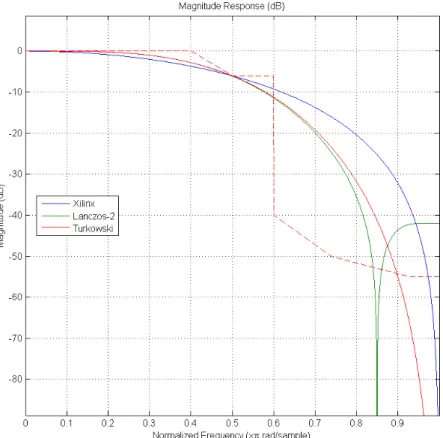
The responses of the chroma resampling filters proposed in the references are compared in figure3.9against the templates defined in Rec.709 and 601. Most of the proposed filters in section
3.2don’t respect the templates defined in Rec. 601 and Rec. 709. However, the majority of these filters have a common 6 dB attenuation at half the sampling frequency, which is a characteristic that was considered in the design of the smaller chroma resampling filters ( section5.5), together with the advise from [35] to keep the pass-band as flat as possible when optimizing a filter’s architecture, lowering the expectations for the stop-band’s attenuation instead.
(a) Xilinx [37], Lanczos-2 [22], Turkowski [38].
(b) BBC [33], Poynton [28], Bartkowiak [36],Akrammullah [32].
Figure 3.9: Comparison of the filters proposed in the references against a template (dashed line) that is compliant with both Rec.601 (figure3.8) and Rec.701 templates (figure3.7).
Chapter 4
Architecture Design
4.1
Introduction
The main design goal of this project is to develop a module that is synthesizable for 600 MHz frequencies at 40 nm technologies. This performance goal is driven from the specification of 4K video formats in the Consumer Electronics Association (CEA) standard of digital television profiles for uncompressed high speed digital interfaces [39].
These 4K progressive formats have active video resolutions of 3840x2160 and 4096x2160 at both 50 Hz and 60 Hz frame rates. Considering the full frame sizes (with vertical and horizontal blanking) of 5280x2250 and 4400x2250 it results in 594 million pixels per second to be transmit-ted, which requires a pixel clock of 594 MHz. Considering a parallel interface, where the three video channels are transmitted in parallel, these formats originate a video data rate of 28,51 Gbps for RGB or YCrCb 4:4:4 16-bits video.
This module implements a parallel video interface with the three video channels and the three synchronization signals in parallel due to compatibility reasons with other modules, as this is the most direct interface to be implemented.
The architecture design for this module is heavily driven by the color space conversion algo-rithm (figure2.4) necessary to support the conversions between the proposed color spaces. This algorithm has been divided in indivisible steps, corresponding to the operations that may need to be executed or bypassed for each conversion configuration.
4.2
Top Level Interface
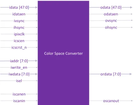
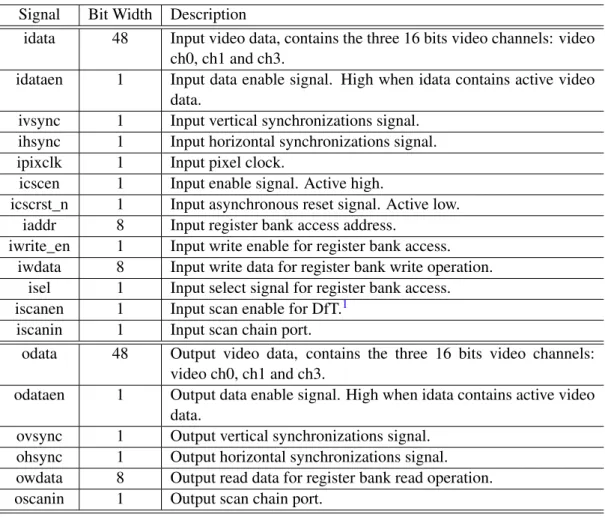
The top level interface (figure4.1) of the developed module requires the support of the video in-terface input and output signals: video data, hsync and vsync. The video data signals are concate-nated in a 48 bits bus with the most significant 16 bits corresponding to the channel 1 (representing R or Y), then channel 2 (G or Cr) and finally the least significant 16 bits correspond to channel 3 (B or Cb signals). A register bank was implemented in the module for configuration of its func-tioning mode, so an interface to access the registers is offered, composed of the following signals:
idata [47:0] ihsync ivsync ipixclk odata [47:0] ohsync ovsync odataen idataen icscen icscrst_n iaddr [7:0] iwdata [7:0] ordata [7:0] iscanen iscanin oscanout isel iwrite_en
Color Space Converter
Figure 4.1: Top level interface
address, write enable, write data, read data and select signal. Finally, the top level has the input ports for the module’s enable, reset and pixel clock signals. The top level interface signals are further described in table4.1.
4.3
Implementation Strategy
The project was divided in different sub-modules corresponding to the tasks performed in the color space conversion - figure4.2. This hierarchical division not only allows for a divide-and-conquer problem solving approach as it allows each module to be tested and validated independently, which facilitates the verification task. Furthermore, because depending on the running configuration not all tasks are needed to the required conversion process, some modules can be simply set to bypass mode.
The color space conversion module was divided in 9 sub-modules: a register bank for con-figuration purposes, a control unit module which controls the datapath concon-figuration based on the register bank data, two chroma horizontal resampling filters, one RGB to RGB color space conver-sion, one gamma encoder and a gamma decoder, one RGB to YCC and an YCC to RGB converters which also perform the limited/full range data conversion.
4.3 Implementation Strategy 31 Ch ro ma U p sa mp le r G a mma D e co d er Y to G co n ve rte r R G B to R G B Co n ve rte r Ch ro ma D o w n sa mp l er G a mma En co d e r R G B to Y co n ve rte r Y Cr Cb to R G B Co n ve rte r Cr Cb to R B Co n ve rte r R G B to Y Cr Cb Co n ve rte r R B to Cb Cr CO n ve rte r v v v v v v v v v v v v v v v v R egi st er B an k C on tr ol U ni t con f C on tr ol P ar am et er s En ab le ,R es et a n d C on tr ol S ign al s to a ll su b -m od u le s En ab le R es et R es et En ab le A dd re ss W ri te D at a R ea d D at a W ri te E n ab le con f W ir e B u s Fr om T op L ev el V id eo C H 0 V id eo C H 1 V id eo C H 2 H sy n c V sy nc P ix el C loc k v D at a En ab le Se le ct Figure 4.2: System architecture. T able 4.1 relates the top-le v el signal’ s naming of figure 4.1 with the higher le v el description of thi s figure.
![Figure 2.2: CIE 1931 chromaticity diagram with sRGB color space represented (from [2]).](https://thumb-eu.123doks.com/thumbv2/123dok_br/15198758.1017776/27.892.319.618.150.487/figure-cie-chromaticity-diagram-srgb-color-space-represented.webp)

![Figure 3.1: Direct implementation of conversion operation from [4].](https://thumb-eu.123doks.com/thumbv2/123dok_br/15198758.1017776/40.892.164.677.158.365/figure-direct-implementation-conversion-operation.webp)
![Figure 3.4: Distributed arithmetic architecture (from [5]).](https://thumb-eu.123doks.com/thumbv2/123dok_br/15198758.1017776/42.892.163.691.160.381/figure-distributed-arithmetic-architecture-from.webp)
![Figure 3.7: Template from Rec.709 for Cr and Cb filtering (from [7]). f s is the sampling frequency of the R,G,B and Y signals.](https://thumb-eu.123doks.com/thumbv2/123dok_br/15198758.1017776/44.892.166.684.150.396/figure-template-rec-cr-filtering-sampling-frequency-signals.webp)
![Figure 3.8: Specification from Rec.601 for a digital filter for sampling-rate conversion from 4:4:4 to 4:2:2 color-difference signals (from [8])](https://thumb-eu.123doks.com/thumbv2/123dok_br/15198758.1017776/45.892.203.716.149.391/figure-specification-digital-filter-sampling-conversion-difference-signals.webp)