Preliminary Specification of Basic
Services and Protocols
G. Blair, C. Brudna, V. Cahill, A. Casimiro,
R. Cunningham, H. Duran-Limon, J. Kaiser,
P. Martins and P. Veríssimo
DI-FCUL
TR–03–18
July 2003
Departamento de Informática
Faculdade de Ciências da Universidade de Lisboa
Campo Grande, 1700 Lisboa
Portugal
Technical reports are available at http://www.di.fc.ul.pt/tech-reports. The files are stored in PDF, with the report number as filename. Alternatively, reports are available by post from the above address.
Project IST-2000-26031
CO-operating Real-time senTient objects:
architecture and EXperimental evaluation
Preliminary Specification of Basic Services and
Protocols
CORTEX Deliverable D5
Version 1.0
Revisions
Rev. Date Comment
0.1 17/01/2003 Draft document for internal review
0.2 12/02/2003 Final draft for comments
1.0 27/02/2003 Final document
Editor
Ant´onio Casimiro, University of Lisboa
Contributors
Cristiano Brudna, University of Ulm Gordon Blair, University of Lancaster Vinny Cahill, Trinity College Dublin Ant´onio Casimiro, University of Lisboa
Raymond Cunningham, Trinity College Dublin Hector Duran-Limon, University of Lancaster J¨org Kaiser, University of Ulm
Pedro Martins, University of Lisboa Paulo Ver´ıssimo, University of Lisboa
Address
Faculdade de Ciˆencias da Universidade de Lisboa Bloco C5, Campo Grande
1749-016 Lisboa Portugal
Contents
1 Introduction 5
2 Overview of basic services and protocols 6
2.1 TCB services . . . 7
2.2 Coverage awareness . . . 9
2.3 Resource and Task model . . . 9
2.4 TBMAC Basic Services . . . 10
2.4.1 Basics . . . 10
2.4.2 Inter-Cell Communication . . . 11
2.4.3 Entering an Empty Cell . . . 12
2.5 CAN . . . 13
2.6 Adaptable Timed Event Service (ATES) . . . 15
3 Service interfaces 18 3.1 TCB API . . . 18
3.2 Resource Management framework . . . 21
3.2.1 Resource model . . . 21
3.2.2 The Resources Meta-object protocol . . . 22
3.3 The Task model . . . 25
3.3.1 Overview . . . 25
3.3.2 Tasks and VTMs . . . 26
3.3.3 Task graph configurations . . . 27
3.4 TBMAC API . . . 28
3.4.1 Initialisation . . . 29
3.4.2 Slot Management . . . 29
3.4.3 Communication . . . 30
3.4.4 Higher layer issues . . . 31
3.5 ATES API . . . 31
4 Definition of Services and Protocols 33 4.1 TCB services and protocols . . . 34
4.1.1 Timestamping Service . . . 34
4.1.2 Local Measurement Service . . . 34
4.1.3 Distributed Measurement Service . . . 36
4.1.4 Timely Execution Service . . . 37
4.1.5 Local Timing Failure Detection Service . . . 38
4.1.6 Communication Module and the Control Channel . . . 41
4.1.7 Distributed Timing Failure Detection Service . . . 41
4.2 Example of the use of the resource and task models . . . 46
4.3 TBMAC protocol messages and inaccessibility . . . 47
4.3.1 TBMAC protocol messages . . . 47
4.3.2.1 Modelling arrival/departures . . . 48
4.3.2.2 Non empty cell . . . 49
4.3.2.3 Empty cell . . . 49
4.4 Content and Cell based Predictive Routing (CCPR) protocol for mo-bile Ad Hoc networks . . . 51
4.4.1 Introduction . . . 51
4.4.2 TBMAC . . . 53
4.4.3 Content and Cell based Predictive Routing (CCPR) protocol . 54 4.4.3.1 The route discovery phase . . . 55
4.4.3.2 The routing path construction phase . . . 56
4.4.3.3 The route maintenance phase . . . 58
4.4.3.4 Keeping the routing tables consistent . . . 59
4.4.4 Related work . . . 60
4.4.5 Conclusion and future work . . . 62
4.5 A real-time event channel model for the CAN-Bus . . . 63
4.5.1 Introduction . . . 63
4.5.2 Events and event channels . . . 64
4.5.2.1 Routing, filtering and binding . . . 65
4.5.2.2 Real-time event channels . . . 66
4.5.3 Event channels on a CAN-Bus network . . . 70
4.5.3.1 The reservation scheme . . . 70
4.5.3.2 Structure of the time-slots . . . 71
4.5.3.3 Scheduling soft real-time- and non-real-time-messages 73 4.5.3.4 Soft real-time messages . . . 73
4.5.3.5 Structuring the CAN message identifier . . . 74
4.5.4 Comparison with related higher level CAN protocols . . . 74
4.5.5 Concluding remarks and future work . . . 75
A Flowchart of the route discovery algorithm 77
1
Introduction
Given the objective of CORTEX to explore the fundamental theoretical and en-gineering issues that will make possible the construction of large-scale proactive applications composed of sentient objects, a preliminary CORTEX system architec-ture has been proposed in a previous deliverable [17]. The proposed architecarchitec-ture explicitly considers two logical scopes in terms of the problems that must be dealt. In one hand, it considers a local scope, which includes all the issues that respect the constitution and operation of CORTEX nodes or collections of nodes, namely interfaces to application objects and supporting/run-time services. On the other hand, a global scope, which addresses the need to accommodate the heterogeneity of environments in which applications will operate, by proposing solutions that fol-low a WAN-of-CANs approach and alfol-low de definition of QoS containment zones and the hierarchical composition of such zones.
In order to materialize this architecture, it is necessary to define a set of services to support the envisaged applications, which will architecturally exist, and will be accessed, locally to a CORTEX node, but which may have a distributed, global scope. In deliverable WP3-D4 we have already presented a preliminary view of the local architecture of a node, where it was possible to identify the above-mentioned supporting services. The present deliverable somehow continues the work that has been presented in previous deliverables, in particular in deliverables WP2-D3 and WP3-D4.
The fundamental objective of this deliverable is to present a preliminary spec-ification of the basic services and protocols that should be provided in CORTEX in order to support the envisaged applications. Although it is still necessary to do some work with respect to the integration of some of the services presented in this deliverable, we believe that the overall view of the required services and protocols, which is presented here, constitutes a fundamental step towards that integration.
In terms of the structure of the deliverable, we try to follow a top-down approach by firstly motivating, in Section 2, the need for some services and by describing and specifying what they should provide (i.e., their properties). However, this approach is not always followed, given that in Sections 4.5 and 4.4 we provide two papers as originally presented, therefore including in those sections all the definitions of required properties and proposed interfaces.
Then, in Section 3, we focus on the services from the perspective of the interfaces they should provide. We believe this makes sense because interfaces can be specified independently of some particular implementation.
The last section focuses on the specific protocols and services to be provided in CORTEX. They implement (at least some of) the interfaces described in Section 3. However, since this is a preliminary deliverable, only on a subset of the services and protocols is presented.
2
Overview of basic services and protocols
In this section we provide an overview of the basic services and protocols that we propose for CORTEX. This set of services can be viewed as a middleware layer that exists below CORTEX applications which provides the adequate abstractions and implements the necessary functionalities required to address the needs of this class of applications.
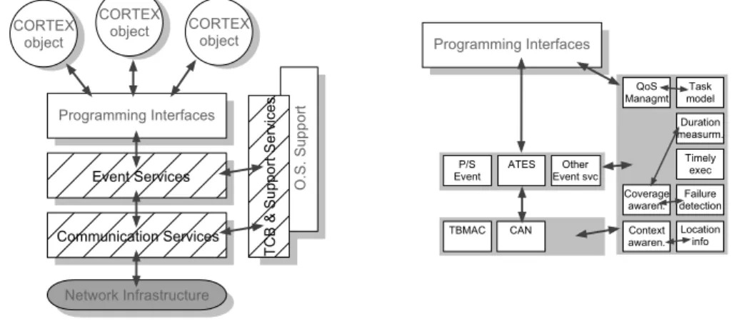
In order to clarify the discussion, and given that it is possible to identify certain groups of services in terms of their purpose, their nature or their location in a service stack, we propose to organize the services and protocols provided in CORTEX in three main groups, as depicted in Figure 1.
O .S . S up po rt P r o g r a m m i n g I n t e r f a c e s E v e n t S e r v i c e s C o m m u n i c a t i o n S e r v i c e s C O R T E X o b j e c t C O R T E X o b j e c t C O R T E Xo b j e c t N e t w o r k I n f r a s t r u c t u r e TC B & S up po rt S er vi ce s C o v e r a g e a w a r e n . L o c a t i o n i n f o F a i l u r e d e t e c t i o n D u r a t i o n m e a s u r m . T i m e l y e x e c A T E S T B M A C P / S E v e n t E v e n t s v cO t h e r C o n t e x t a w a r e n . T a s k m o d e l Q o S M a n a g m t P r o g r a m m i n g I n t e r f a c e s C A N
Figure 1: Block diagram of CORTEX basic services.
At a lower level of the architecture we find a group of basic communication services and protocols, which are implemented directly on top of the network in-frastructure and enforce abstract network properties such as those related with the provision of guaranteed communication latency or reliability. More specifically, at the right hand side of the figure it is possible to observe that we specifically focus on the CAN controller area network (to provide predictable communication at the CAN level of the WAN-of-CAN structure of CORTEX), and on TBMAC, a protocol specifically designed to address predictability requirements over wireless communi-cation infrastructures.
Above the communication level it is possible to consider that a set of event re-lated services exists. The most relevant service at this level implements the required anonymous communication, based on the publish-subscribe paradigm. Several is-sues, such as discovery/announcement of events, filtering, and routing of events to interested subscribers, is addressed at this level. Another important aspect is related with the need to address non-functional requirements of applications, namely those concerning timeliness. One approach is provided with the ATES service, which aims at providing the means to integrate timeliness requirements in event-based commu-nication. This is also done with the help of some supporting services, those that constitute the third group here considered.
The Timely Computing Base (TCB) can be seen as an oracle that provides a few very basic but fundamental services to the rest of the system, and is therefore orthogonal to the architecture. Since there exist other support services besides the
TCB, they must be all included in the same group of services, as represented in Figure 1. These other support services, which include QoS management, coverage awareness and context awareness, are also generic services that may be useful as building blocks for implementing the rest of the system (both other middleware services and the applications).
The rest of this section will focus on all these services, providing a motivation for their need and, whenever possible, stating the properties which more formally characterize them.
2.1
TCB services
As described in deliverable WP3-D4 [17], the Timely Computing Base (TCB) can be seen as a special architectural component serving the whole system and providing crucial time related services. In this section we will review the basic TCB properties, those that must be exhibited by a TCB component, which will serve to understand the specification of the services to be provided at the TCB API. This API, which was already presented in deliverable WP3-D4, will be summarized in Section 3.1. The details relative to the internal definition and implementation of TCB services and protocols are presented in Section 4.1.
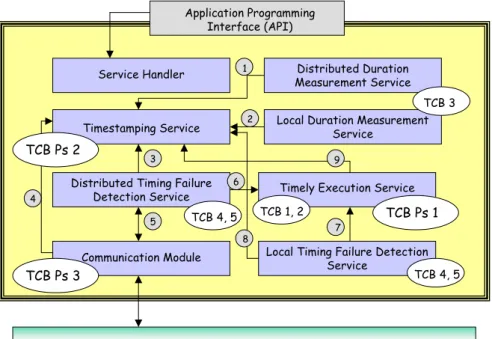
Figure 2 illustrates the modular composition of a TCB component. The inter-action (locally to a site) between payload applications and the TCB component is made through a TCB API. However, the TCB can be internally composed of sev-eral modules, which implement the necessary protocols and (internal and external) services.
Distributed Timing Failure Detection Service
Communication Module
Timely Execution Service
Local Timing Failure Detection Service
Application Programming Interface (API)
Local Duration Measurement Service Distributed Duration Measurement Service Service Handler Timestamping Service TCB Ps 1 TCB Ps 3 TCB 1, 2 TCB 3 TCB 4, 5 TCB 4, 5 1 2 3 4 5 6 8 7 9 TCB Ps 2 Control Channel
Figure 2: Architecture of a TCB Component.
Let us review the fault and synchronism model specific of the TCB subsystem. We assume only crash failures for the TCB components, i.e. that they are fail-silent.
Furthermore, we assume that the failure of a local TCB module implies the failure of that site, as seen from the other sites. The crash of a local TCB is easily detected by the other TCB instances and does not affect application processes in other sites (local processes do not exist anymore after a TCB crash). The TCB subsystem enjoys the following synchronism properties:
TCB Ps 1 There exists a known upper bound TD1
max on processing delays TCB Ps 2 There exists a known upper bound TD2
max on the drift rate of local TCB clocks
TCB Ps 3 There exists a known upper bound TD3
max on the delivery delay of mes-sages exchanged between local TCBs
Property TCB Ps 1 refers to the determinism in the execution time of code elements by the TCB. Property TCB Ps 2 refers to the existence of a local clock in each TCB whose individual drift is bounded. This allows measuring local durations, that is, the interval between two local events. These clocks are internal to the TCB. Property TCB Ps 3 completes the synchronism properties, referring to the determinism in the time to exchange messages among TCB modules in different sites (each site is supposed to have a local TCB module). It is assumed that inter-TCB channels provide reliable delivery, that is, no messages addressed to correct TCBs are lost. The set of all local TCB modules, interconnected by the control channel, constitutes the distributed TCB.
Timely Execution
TCB 1 Eager Execution: Given any function f with an execution time bounded by T , the TCB is able to execute f within T from the execution start instant TCB 2 Deferred Execution: Given any function f and some delay amount T , for any deferred execution of f triggered at real time t, the TCB will not execute f within T from t
Duration Measurement
TCB 3 Given any two events occurring in any two nodes at instants ts and te, the TCB is able to measure the duration between those two events with a known bounded error. The error depends on the measurement method.
Timing Failure Detection
TCB 4 Timed Strong Completeness: Any timing failure is detected by the dis-tributed TCB within a known interval from its occurrence
TCB 5 Timed Strong Accuracy: Any timely action finishing no later than some know interval before its deadline is never wrongly detected as a timing failure
Table 1: Basic services of the TCB.
Because the TCB must be a very simple component, it only provides the ser-vices considered to be essential to satisfy a wide range of applications with timeli-ness requirements: ability to measure distributed durations with bounded accuracy;
complete and accurate detection of timing failures; ability to execute well-defined functions in bounded time. Table 1 presents an informal summary of these services (a more detailed presentation was provided in deliverable WP3-D4).
These are the services to be provided at the TCB interface shown in Figure 2. In this figure it is also possible to see the interactions performed among the several modules defined in the component, represented by arrows. The oval shapes labelled with TCB Ps x refer to the synchrony properties preserved by the TCB, and the ones labelled with TCB x indicate the properties that each module should fulfil in order to provide only correct services to user applications.
The specific definition of the TCB API will be provided in Section 3.1.
2.2
Coverage awareness
The coverage awareness service has been presented in WP2-D3, as a supporting or enabler service for dependable QoS adaptation. The integration between this service and the other support services, namely the TCB services, was also discussed in WP2-D3. Therefore, it is our understanding that it does not make sense to describe this service once again in the present deliverable.
2.3
Resource and Task model
Over the last few years we have seen the proliferation of embedded mobile systems such as mobile phones and PDAs. Pervasive computing is also taking off in which multiple cooperating possibly embedded controllers are used. A new kind of appli-cations can now be envisaged with the emergence of both mobile computing and ubiquitous computing. Applications of such kind are characterised by being largely distributed and proactive, i.e. able to operate without human intervention. A set of further characteristics are also involved such as self context awareness as a means to sense the surrounding environment. Examples of these applications include au-tomatic car control systems in which cars are able to operate independently and cooperate with each other to avoid collisions. Another example is an air traffic control system whereby thousands of aircrafts are proactively coordinated to keep them at safe distances from each other, direct them during takeoff and landing from airports and ensure that traffic congestions are avoided. Smart office systems can also be foreseen in which the intensity of light, room temperature and some other features are automatically tuned according to the user preferences of the persons present in the room.
The CORTEX Project is examining fundamental issues relating to the support of such applications, including the development of middleware for this domain. Impor-tantly, CORTEX applications require the support of anonymous and asynchronous event models, i.e. scenarios including large number of autonomous processing units where a many-to-many communication takes place are well-suited to the anonymous dissemination of information. In addition, systems in which frequent disconnection is likely to happen are well-supported by asynchronous communication as block-ing conditions are avoided. Further requirements include support for mobility and non-functional properties such as timeliness and reliability since some of these appli-cations are time-critical. However, current event-oriented middleware technologies do not provide a solution for all the challenges imposed by these applications. As
regards timeliness requirements, we believe that resource management plays an im-portant role in providing support for real-time applications. The mechanism that allocates resources in the system should ensure that critical activities will be pro-vided with enough resources to carry out their tasks in a predictable way. Changes in the availability of network resources and periods of disconnection are frequently experienced as mobile computing environments are highly dynamic. This kind of unexpected changes in the environment implies that a means for adapting the system in a dependable way needs to be introduced. Furthermore, mobile applications typ-ically operate on devices with scarce resources, e.g. CPU capacity, system memory and battery life. Therefore, support for the predictable and efficient management of the system resources as well as resource reconfiguration capabilities for achieving adaptation are required. An example of the latter is a redistribution of both CPU-time and memory to the set of activities that the system performs, thus, ensuring that time-critical activities are not disturbed.
Section 3.2 presents a resource management framework which provides support for addressing the timeliness issues mentioned above. The framework makes use of both reflection and component technology. Reflection is a means by which a sys-tem is able to inspect and change its internals in a principled way [52]. Basically, a reflective system is able to perform both self-inspection and self-adaptation. To accomplish this, a reflective system has a representation of itself. This representa-tion is causally connected to its domain, i.e. any change in the domain must have an effect in the system, and vice versa. A reflective system is mainly divided into two parts: the base-level and the meta-level. The former deals with the normal aspects of the system whereas the latter regards the system’s representation. The meta-level interface is often referred to as the meta-object protocol (MOP) [46]. On the other hand, component technology provides great flexibility for the dynamic replacement of components. In addition, the component approach promotes and enhances software reusability. However, component technologies are not mature enough yet. New component standards, such as EJB [57] and the CORBA compo-nent model [29], have started to emerge and will consolidate in the next few years. In fact, the implementation of our resource system is developed in OpenCOM [51], which is a lightweight, efficient and reflective model based on Microsoft’s COM [55].
2.4
TBMAC Basic Services
In this section the Time-Bounded Medium Access Control (TBMAC) proto-col [20, 17] will be reviewed. This section covers background information about the TBMAC protocol that is needed for the discussion in the rest of the deliver-able. In particular, building on this review Section 3.4 will present the Application Programmer Interface (API) of the TBMAC protocol provided to higher layers. Fi-nally, Section 4.3 provides an overview of the protocol messages used in the TBMAC protocol and a discussion about the inaccessibility of the TBMAC protocol.
2.4.1 Basics
The Time-Bounded Medium Access Control (TBMAC) protocol is based on time-division multiple access with dynamic but predictable slot allocation. TBMAC uses a lightweight atomic multicast protocol to achieve distributed agreement on slot allocation and employs location information to minimise contention for slots.
6 1 2 3 4 5 0 2 4 3 5 4 0 6 3 1 2 6 1 5 0
Figure 3: Possible Cell and Channel allocation.
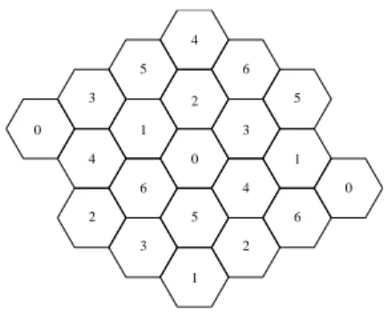
To reduce the probability of the transmissions colliding, the geographical area occupied by the mobile hosts is statically divided into a number of geographical cells. Each cell is numbered and can have arbitrary shape and size but for simplicity, we assume that the cells are hexagons of equal size as illustrated in Figure 3. Each numbered cell is also allocated a distinct radio channel (or CDMA spreading code) to use, maximising the total overall bandwidth available in the ad hoc network.
The boundaries of each of these cells are known to each mobile host in the ad hoc network. To meet this requirement, each mobile host requires access to location information (such as GPS). By a mobile host knowing the cell that it is in, it can then infer the correct radio channel to use.
To further reduce the possibility of collisions, TBMAC divides access to the wireless medium within a cell into two time periods:
1. Contention Free Period (CFP)
2. Contention Period (CP)
Both the CFP and the CP are divided into slots and each period lasts a well-known period of time. Once a mobile host has been allocated a CFP slot, it has predictable access to the wireless medium. The mobile host can then transmit data in its slot until it leaves the cell or fails.
Mobile hosts, that do not have CFP slots allocated to them, contend with each other to request CFP slots to be allocated to them in the CP. The CP is used by mobile hosts that arrive into the cell or that have recently powered on in the cell.
The TBMAC participants reach a distributed agreement on the order of alloca-tions and deallocation of CFP slots. The approach TBMAC uses to provide a total ordering protocol within a cell is to use the synchronous atomic broadcast protocol from Flaviu Cristian [18].
By fixing the number of slots in the CFP, it would appear that we are placing an upper bound on the number of mobile hosts that can be allocated a CFP slot in the cell at any one time. This would mean that the TBMAC protocol is very restrictive and has only limited use. It is possible however to overcome this restriction by allowing a dynamic logical CFP (LCFP) to grow and shrink in the repeating static CFPs [20].
2.4.2 Inter-Cell Communication
As the area occupied by the mobile hosts has been divided up into geographical cells and each cell has been allocated a particular radio channel to use, an obvious
ques-tion is how does a mobile host communicate with other mobile hosts in neighbouring cells.
If we consider two adjoining cells A & B, then TBMAC uses a static CFP slot for communication from cell A to cell B and another static CFP slot for communication from cell B to cell A. Mobile hosts then atomically broadcast a request to be granted the inter-cell CFP slot. When a mobile host transmits in the inter-cell slot, all the mobile hosts in the adjoining cell will be listening for this transmission.
By using two static CFP slots, it would appear at first glance that TBMAC is placing a severe restriction on the communication between mobile hosts in adjoining cells. However, as we shall see in section 4.3.1, it is possible to allow a dynamically varying number of CFP slots for inter-cell communication.
2.4.3 Entering an Empty Cell
When dividing access to the medium into CFP slots and the CP slots, the most difficult task is to allocate the first CFP slot to a mobile host in a cell. Once there is one mobile host in the cell with a CFP slot then it is possible to use the atomic broadcast protocol to allocate and deallocate slots.
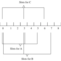
In TBMAC, a mobile host in an empty cell generates a list of CFP slots to use after listening for one full CFP as illustrated in Figure 4.
0 1 2 3 4 5 6 7 8
Slots for B Slots for C
Slots for A
Figure 4: Generated list of slots.
During the next CFP, the mobile host transmits in each CFP slot in its generated list (including the Slot Bitmap in each transmission). The mobile host also listens in each of the other CFP slots that it does not transmit in to gain knowledge about the presence of other mobile hosts and the CFP slots that they are using.
When two or more mobile hosts enter an empty cell and generate a list of CFP slots to use, each mobile host has an inconsistent view of the allocation of CFP slots. After a known number of CFPs (M say), the view of each mobile host of the allocation of CFP slots converges to a consistent view. Figure 5 illustrates how this convergence is achieved.
When a mobile host transmits in each of its generated CFP slots, the mobile host includes information about the other generated slots that it is using. When a mobile host successfully receives a message from another mobile host, the receiving mobile host obtains a list of slots being used by the transmitting mobile host. If a
CFP 1 CFP 2 CFP 3 MH A MH B MH C Slots {0,3,7} Slots {0,3,5} Slots {0,3,6} Slots {5,6,7} Collisions {0,3} Collisions {0,3} MH B MH A Slots {6,7} Slots {6,7} Collisions {0,3} MH C Omission failure in slot 7 MH A Slots {5,6,7} Collisions {0,3} MH B Slots {5,6,7} Collisions {0,3} Slots {5,6,7} Collisions {0,3} MH C Time
Figure 5: View Convergence of Slot Allocations.
mobile host realises that one of its CFP slots is causing a collision, then the mobile host stops transmitting in this slot in subsequent CFPs.
2.5
CAN
The WAN-of-CAN Structure plays an major role in the CORTEX network archi-tecture. CANs (Controller Area Networks) connect islands of tightly cooperating autonomous computing nodes. At an abstract layer, a CAN constitutes a zone of coherent QoS provision. This may be a fieldbus, an Ethernet, or even a wireless network like bluetooth or an 802.11 infrastructure network. We assume a certain guaranteed level of predictability as an intrinsic property of CANs which usually is considerably higher than what we can expect from WANs. Therefore, although CANs may have a wide spectrum of what level of predictability they provide, their basic protocol mechanisms assist the architecture of higher level communication schemes which allow to define temporal bounds on communication beyond a purely best effort probabilistic approach (although it must be admitted that any system can only guarantee probabilistic bounds!). This actually distinguishes them from WANs where we do not make such assumptions. On a CAN, the protocol and ser-vices allow the specification of time bounds and provide mechanisms to enforce these constraints.
In the general interaction model of CORTEX, a CAN may usually link the smart components of a sensor system to the respective computational engines or directly to smart actuators. These components are embodied in an artefact like a smart door, a car, a robot or similar stationary and mobile entities.
Two major issues have to be considered for services and protocols on CANs for the CORTEX specific application environments:
2. A range of timeliness and reliability requirements have to be supported for the dissemination of events.
The basic interaction abstractions are events and event channels through which events are disseminated. An event is specified by a subject and functional and non-functional attributes. The functional attributes reflect the context in which the event was generated, like the location, the time, the mode of operation, etc. The non-functional attributes are related to temporal and reliability issues. They may comprise deadlines for delivery, expiration dates, a coverage and similar parame-ters. Thus, to a large extend the non-functional attributes of an event specify the requirements for the underlying communication system.
The event channel abstracts the underlying communication system. In appli-cation areas like those envisaged in CORTEX [15] non-functional attributes like timeliness and reliability are decisive to support critical system functions. Particu-larly in a CAN we need to support critical control loops. Hence, the communication system has to provide the adequate resources to meet the respective QoS require-ments. An event channel is specified by a subject defining the events which can be disseminated by the channel and non-functional attributes. These attributes char-acterize the timeliness and reliability properties of the channel, like latencies and the tolerable omission degree. Thus an event channel allows to specify quality pa-rameters explicitly which must be mapped to the underlying network. When setting up an event channel, the respective resources will be allocated.
As a matter of fact, there is a trade-off between the predictability of commu-nication and the needed resources. At the safe end, all commucommu-nication is statically planned and resources have to be assigned anticipating worst case load and failure assumptions. However, this may only be required for a small number of highly crit-ical services. In fact, critcrit-ical system services as the TCB [17] could use such highly predictable links to meet its temporal and reliability requirements. Other examples on the application level are tight sensor/actor control loops e.g. for crash avoidance or motor and brake control. In most cases less critical events have to be accom-modated by the communication system which also allow a more dynamic system behaviour. However, also for these events, temporal parameters may be needed, e.g. the specification of when an event should be delivered or how long the event is valid. The different requirements are reflected by event channel classes with different properties.
On the architectural level, we distinguish three layers. Figure 6 roughly depicts the layers and the respective abstractions. It relates to Figure 1 provided in the introduction in that the upper middleware layer provides the event specific services. On the publisher/subscriber layer, the main abstractions are events and different classes of event channels. The layer enables the application to specify channels of different QoS classes and to publish events and subscribe to channels with the respective guarantees.
Mapping the abstractions of the publisher/subscriber layer directly to the un-derlying network is a tough challenge because the usual abstractions on the network layer are low level messages. Hence, this layer does not match the requirements of group communication, subject-based addressing or the QoS specifications defined for channels. Therefore, an abstract network (AN-) layer is introduced which enriches the properties of the raw network (this may not just be a physical network, but a specific MAC-layer or even a higher OSI level) by additional properties and
com-the TCB [WP3-D4] could use such highly predictable links to meet its temporal and reliability requirements. Other examples on the application level are tight sensor/actor control loops e.g. for crash avoidance or motor and brake control. In most cases less critical events have to be accommodated by the communication system which also allow a more dynamic system behaviour. However, also for these events, temporal parameters may be needed, e.g. the specification of when an event should be delivered or how long the event is valid. The different requirements are reflected by event channel classes with different properties.
On the architectural level, we distinguish three layers. Fig 1 roughly depicts the layers and the respective abstractions. It relates to Fig. xx (the figure Antonio provided in his mail) provided in the introduction in that the upper middleware layer provides the event specific services.
Fig. 1 Architectural Layers
On the publisher/subscriber layer, the main abstractions are events and different classes of event channels. The layer enables the application to specify channels of different QoS classes and to publish events and subscribe to channels with the respective guarantees.
Mapping the abstractions of the publisher/subscriber layer directly to the underlying network is a tough challenge because the usual abstractions on the network layer are low level messages. Hence, this layer does not match the requirements of group communication, subject-based addressing or the QoS specifications defined for channels. Therefore, an abstract network (AN-) layer is introduced which enriches the properties of the raw network (this may not just be a physical network, but a specific MAC-layer or even a higher OSI level) by additional properties and communication services as e.g. some form of reliable broadcast or group communication and temporal guarantees for the message transfer.
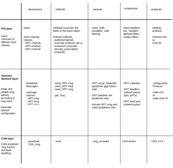
As an example, Fig. 2 presents the preliminary specification of protocols and services for a particular CAN (CAN-Bus [Bos91]). It lists the basic abstractions, the methods to deal with these abstractions, the system services available, the components to realize the system services and specific protocols needed to support the abstractions in the distributed architecture. The P/S layer supports events and different classes of event channels with different quality properties. It should be noted that the QoS properties in general depend on what the abstract network layer can provide. Thus, it may not always be possible to e.g. support a hard real-time event channel because the abstract network layer can not provide the
publisher/ subscriber layer application layer abstract network layer network layer QoS assurance Functional abstractions middleware
events with context and temporal properties, event channels with quality properties
message classes,
messages with temporal properties, network reliability properties
network dependent best effort message transfer
Figure 6: Architectural layers.
munication services as e.g. some form of reliable broadcast or group communication and temporal guarantees for the message transfer.
As an example, Figure 7 presents the preliminary specification of protocols and services for a particular CAN (CAN-Bus [28]). It lists the basic abstractions, the methods to deal with these abstractions, the system services available, the compo-nents to realize the system services and specific protocols needed to support the abstractions in the distributed architecture. The P/S layer supports events and dif-ferent classes of event channels with difdif-ferent quality properties. It should be noted that the QoS properties in general depend on what the abstract network layer can provide. Thus, it may not always be possible to e.g. support a hard real-time event channel because the abstract network layer can not provide the respective guaran-tees. Therefore, the event channel classes supported are dependent on the zones in which publishers and subscribers reside. Figure 7 covers the case of a single zone which is a CAN-Bus.
A detailed description of these abstractions and the mechanisms to enforce them on a CAN-Bus[28] is provided in Section4 of this deliverable with the title: ”A Real-Time Event Channel Model for the CAN-Bus”. The dynamic binding protocol of the P/S layer and the configuration protocol of the AN-layer are described in [17, 44].
2.6
Adaptable Timed Event Service (ATES)
A proposed solution to handle some of the timeliness requirements of CORTEX system entities is by using a specialized architectural building block, the Timely Computing Base, which provides a set of fundamental services tailored for that purpose. However, since the services provided by the TCB are just the essential ones in order to keep the TCB small, simple and hence reliable, the interface supplied by the TCB is, in a certain way, a low level interface, which should be hidden from sentient objects in the programming model.
The Adaptable Timed Event Service (ATES ) is a middleware event service that extends the CORTEX publish/subscribe programming model with constructors to deal with timeliness requirements. ATES hides from sentient objects the low level services provided by the TCB concerning timing failure detection, coverage stability and awareness, and timely execution, providing high level abstractions more suitable
respective guarantees. Therefore, the event channel classes supported are dependent on the zones in which publishers and subscribers reside. Fig. 2 covers the case of a single zone which is a CAN-Bus.
Fig. 2 Properties, Services and Protocols of Architectural Layers
A detailed description of these abstractions and the mechanisms to enforce them on a CAN-Bus [Bos91] is provided in chapter 4 of this deliverable with the title: "A Real-Time Event Channel Model for the CAN-Bus". The dynamic binding protocol of the P/S layer and the configuration protocol of the AN-layer are described in [WP3-D4, KaB02].
P/S-layer
Abstract Network layer
CAN-layer
abstractions methods services
event event channel classes: - HRT-channel, - SRT-channel, - NRT-channel broadcast Messages message classes: - HRT-msg - SRT-msg - NRT-msg
methods to access the fields of the event object channel methods: - publish(channel), - subcribe (channel, attr.)), - announce (channel) - discard_subscription (channel) - send_HRT-msg - send_SRT-msg - send_NRT-msg - get_msg - event_notif., - exception_notif. - filtering send prioritized CAN_msg msg_received components protocols - binding protocol: channel UID to CAN-ID - configuration Protocol: node-UID to node short ID - HRT-calendar - SRT deadline ordered queue (dyn. prio‘s) - NRT fixed prio. ordered queue - event-handlers - exc. handlers - attribute filters - subject filters
CAN drivers CAN 2.0 b timely and reliable msg delivery according to msg class, automatic network configuration CAN prioritized msg transm. and fault- handling event channels of different QoS classes - HRT-excpt. Detection (publisher and subscr. site)
- SRT-deadline viol. (publisher site) - discard SRT-msg and notify (publisher site)
Figure 7: Properties, services and protocols of architectural layers.
for application programming.
In this context, the main goal of ATES is to extend the CORTEX programming model in order to enable the definition of timeliness requirements of sentient objects. Events on ATES are timed, in the sense that they must be produced, dissem-inated and consumed at the subscribers within certain timing constraints. Since ATES is a middleware component executing on the payload part of the system (ac-cordingly to the TCB system model), it can only provide guarantees with respect to the timely production, dissemination and consumption of events, as allowed by the underlying payload system. However, by using the timing failure detection service of the TCB, ATES can take advantage of the semantics of this service in order to en-force the timely execution of safety procedures when the specified timing constraints are not fulfilled.
whose correctness depends on the time required to execute some actions. How-ever, since the environments envisaged in CORTEX are characterized by attributes like openness, heterogeneity and large-scale, they exhibit poor baseline properties with respect to timeliness and reliability. Therefore, the ability to satisfy the tim-ing constraints of applications can be compromised or, in other words, it may be difficult to enforce the coverage of timing assumptions, which may degrade over the execution.
ATES provides appropriate constructors to cope with the temporal uncertainty of the environment. Adaptability results from the capacity of ATES to provide operation modes (appropriate for the construction of some application classes) in which coverage awareness can be used as a means to ensure coverage stability.
In ATES, the specification of timeliness requirements is made through < bound, coverage > pairs, where a certain timing bound must be satisfied with a probability indicated by coverage. One of the adaptation modes provided by ATES can be used to ensure that the coverage stability property is preserved. Roughly speaking, in this operation mode ATES will dynamically adjust the relevant timing variables in order to meed the dynamics of the environment. More specifically, ATES will adjust the bound value that is used by the application in order to maintain the coverage near to the desired value. ATES provides another operation mode, which can be described as a coverage awareness mode, in which it dynamically estimates the coverage that is actually possible to provide for a given bound, and lets the ap-plication know of this coverage. ATES implements these adaptation functionalities using the TCB QoS extensions that were presented in another deliverable [16].
ATES notifies sentient objects of changes on the available QoS by calling adapta-tion procedures previously defined by sentient objects. Moreover, ATES guarantees that these adaptation procedures are triggered in real-time, that is, upon detecting changes on the available QoS ATES immediately executes the proper adaptation procedures. For that, the timely execution service of the TCB is used. Section 3.5 will present the ATES application programming interface (API).
3
Service interfaces
3.1
TCB API
A TCB component provides services through a well defined API to user applications that execute on the payload part of the system. Observe that this interface must ensure a correct interaction between a synchronous TCB component and potential asynchronous applications. No timing assumptions are made regarding user appli-cations, whereby the latency on service invocation is not bounded. The same is also true for processing the data provided by the TCB, like the ones resulting from service requests performed by applications.
Duration Measurement
The timestamping service of the TCB is provided through the following function:
timestamp ← getTimestamp ()
Since applications execute on the payload part of the system, a timestamp pro-vided by the TCB is necessarily affected by the latency of the service invocation. This means that no guarantees can be given about the time at which the timestamp is used and, therefore, about the accuracy of this timestamp in absolute terms. Nevertheless, it is possible to measure the duration of an interval bounded by the instants reflected by two timestamps. If a computation takes place during the men-tioned interval, that is, between the two timestamping operations, it is possible to obtain an upper bound for its execution time. The TCB provides support for measuring local durations through the following functions:
id ← startLocalMeasurement (Tevt start)
Tevt end, duration ← endLocalMeasurement (id)
The function startLocalMeasurement is used to begin a measurement oper-ation of a local action started at Tevt start. The operoper-ation is identified inside the TCB by id. To finish a measurement operation, an application must call the function endLocalMeasurement providing the respective id. The service returns a timestamp that signals the end of the measured interval (Tevt end) and, obviously, the measured duration (duration).
The TCB also provides support for distributed measurements. A distributed measurement is a measurement of a distributed duration, resulting from the ex-ecution of a distributed action between two different nodes of the system. The most simple distributed execution corresponds to the transmission of a message through the (payload) communication channel. The distributed duration measure-ment service provides the following two functions (only service specific parameters are indicated):
← sendMessage (Tevt start)
Tevt end, duration, error ← receiveMessage ()
It is assumed that messages can be broadcast on the communication channel and therefore several processes may execute the function receiveMessage. The
parameters are similar to the ones of the local measurement service, except for the return value error of the receiveMessage function, corresponding the the mea-surement error. Note that a meamea-surement algorithm must be used, which delivers an upper bound for the measurement to which corresponds a given error. This function exhibits a blocking behavior, waiting for a message to be received on the payload communication channel. Upon returning, Tevt end contains a timestamp corresponding to the instant at which the TCB received the message.
Timely Execution
The timely execution service of the TCB supports the execution of small and sporadic tasks, satisfying their timeliness requirements. The timely execution service guarantees that the execution of a function will finish before a specified deadline and will not start before a specified liveline. The interface of this service has the following specification (note that this specification merges both eager and deferred execution, corresponding respectively to properties TCB 1 and TCB 2 as described in Section 2.1):
Tevt end ← startExecution (Tevt start, delay, max exec, func)
The deadline for the execution of func is given by the parameters Tevt start and max exec. The former indicates a reference instant for the execution start. The latter, a duration specifying the maximum execution time, can be summed to Tevt start to obtain the deadline for the execution. The parameter delay specifies the deferral time for starting the execution of func, to be counted from Tevt start. The service returns Tevt end, which indicates the termination instant signaled by the TCB for the execution of func. An invocation of this service blocks the calling application until the end of the execution.
Observe that it is not possible to accept all service invocations, either because of intrinsic impossibility to satisfy the parameters defined for request (for instance, if a TCB receives a request for an execution that must finish before a deadline t at some time after t), or because of feasibility constraints related with scheduling the request, given the available (processing) resources at the moment the request is issued.
Timing Failure Detection
The ability to detect timing failures in a timely manner is perhaps the most important service provided by the TCB. The timing failure detection service may be used to simplify the development of applications and to improve their reliability. Similarly to the duration measurement service, the timing failure detection service is divided into a service for detecting local timing failures and into another for detecting distributed timing failures. The following two functions describe the interface of the local timing failure detection service:
id ← startLocalDetection (Tevt start, spec, func, deadline)
Tevt end, delay, faulty ← endLocalDetection (id)
The service is started by invoking the function startLocalDetection. The timestamp Tevt start indicates the start of the observed action and spec the
max-imum duration allowed for its execution. The service must detect failures in a timely manner, therefore it does not accept requests for the observation of timed actions that have already failed. Timely detection implies that if the execution of an action fails the TCB can timely execute a procedure in response to the timing failure, a the procedure specified in func, which must be concluded within a deadline from the instant at which the timing failure occurs. The particular function that handles the timing failure depends on the application logic. This function may execute a variety of actions, ranging from doing a fail-safe shutdown of the system to the update of variables or the execution of low-level I/O commands to controls external devices. For instance, consider the example of an application that controls the operation of an external hardware device. If the system is unable to secure the correct operation of the device due the occurrence of a timing failure, the function (func) must exe-cute the necessary operations in order to stop the device operation in a safe state. Observe that the TCB can use the timely execution service to internally execute func (in this case with a non blocking semantic).
To terminate an observed execution, an application must call the function endLocalDetection in order to deactivate the failure detection and to receive the results of the respective execution, comprising the instant signaled by the TCB for the final of the execution (Tevt end), its duration (delay) and a flag to indicate if the execution was timely or faulty.
A distributed action requires that at least one message is exchanged between two processes and allows to observe execution times of actions whose start and end events are causally connected by a such message. A distributed action may be carried out among several processes (such as when a message is broadcast). In such cases, the execution on each distributed interaction must be observed individually.
The service is supplied by the following functions:
id ← sendMessageTFD (Tevt start, spec, func, deadline) id ← sendMessageWRemoteTFD (Tevt start, spec, func, deadline)
id ← receiveMessage ()1
Tevt end ← endDistAction (id)
duration 1, faulty 1, lateness degree 1 ... duration n, faulty n,
lateness degree n ← waitInfo (id)
Either sendMessageTFD or sendMessageWRemoteTFD can be used to start a tim-ing failure detection operation. These functions differ in the way and place where the timely execution of the handler is done. In the former case, func is executed as soon as a timing failure is detected on the sender side. In the latter, func is exe-cuted on receiver side. The timestamp Tevt start signals the start of the observed action and spec specifies the duration allowed for the execution. If a timing failure occurs the function func must be concluded within a deadline. Each operation has an unique id.
To signal the TCB of the termination of a distributed action, endDistAction can be used after the associated message on the payload channel is returned by
1
receiveMessage is a polymorphic function. When a received message is concerned to a dis-tributed measurement operation the function returns Tevt end, duration and error. Otherwise, the received message is associated to a timing failure detection operation in which case the function returns id.
receiveMessage. The function endDistAction returns a timestamp (Tevt end) that contains the instant at which the TCB has received and marked the termination indication.
To obtain the results of the distributed execution observed by the timing failure detection service it is necessary to call waitInfo. This function will block the calling application until the TCB is able to provide all the information relative to the completion of the operation identified by id. This includes measured durations (duration x), failure status (faulty x) and lateness degrees (lateness degree x) relative to all destinations addressed involved in the distributed execution.
3.2
Resource Management framework
3.2.1 Resource model
The most important elements of the resource model are abstract resources, resource factories and resource managers [25]. Abstract resources explicitly represent system resources. In addition, there may be various levels of abstraction in which higher-level resources are constructed on top of lower-higher-level resources. Resource managers are responsible for managing resources, that is, such managers either map or mul-tiplex higher-level resources on top of lower-level resources. Furthermore, resource schedulers are a specialisation of managers and are in charge of managing processing resources such as threads or virtual processors (or kernel threads). Lastly, the main duty of resource factories is to create abstract resources. For this purpose, higher-level factories make use of lower-higher-level factories to construct higher-higher-level resources. The resource model then consists of three complementary hierarchies corresponding to the main elements of the resource model. Importantly, virtual task machines (VTMs) are top-level resource abstractions and they may encompass several kinds of resources (e.g. CPU, memory and network resources) allocated to a particular task. team memory physical memory VPi VPj CPU
thread k thread l memory Fact
thread Fact VPFact VTMFact team Fact VTM memory Mgr thread Sched VPSched VTMSched team Sched
(a) A hierarchy of abstract resources (b) A factory hierarchy (c) A manager hierarchy
Figure 8: A particular instantiation of the Resource Meta-model.
As an example, a particular instantiation of the framework is shown in Figure 8 (note, however, that the framework does not prescribe any restriction in the number of abstraction levels nor the type of resources modelled). At the top-level of the resource hierarchy is placed a VTM, as shown in Figure 8(a), which encompasses both memory buffer and a team abstraction. The team abstraction in turn includes
two or more user level threads. Moreover, a user level thread is supported by one or more virtual processors (VPs), i.e. kernel level threads. At the bottom of the hierarchy are located physical resources. In addition, a VTM factory is at the top of the factory hierarchy and uses both a memory and a team factory. The team factory then is supported by both the thread and the virtual processor factory as depicted in Figure 8(b). Finally, the manager hierarchy is shown in Figure 8(c). The team scheduler and the memory manager support the VTM scheduler to suspend a VTM by temporally freeing CPU and memory resources respectively. The thread scheduler in turn allows the team scheduler to suspend its threads. Finally, the VP scheduler supports the preemption of virtual processors. Conversely, this hierarchy also provides support for resuming suspended VTMs.
3.2.2 The Resources Meta-object protocol
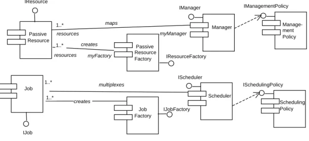
The component types of the resource model are shown in Figure 9. Such com-ponent diagram may be used to support a particular instantiation of the resource framework. Passive resource components represent non-processing resources such as system memory and battery life. In contrast, jobs are capable of performing some activity, that is, they receive messages and process them. Both passive resources and jobs are created by factories as shown in Figure 9. In addition, passive resources are managed by managers. However, since jobs are processing resources, they are managed by schedulers instead. In addition, a management policy component deter-mines the management strategy that managers employ. Similarly, schedulers use a scheduling policy component for determining the execution order of their associated jobs. creates maps resources myFactory 1..* 1..* resources myManager multiplexes creates Passive Resource Job 1..* 1..* Passive Resource Factory Job Factory Manager Scheduler Manage-ment Policy Scheduling Policy IManager IScheduler IResourceFactory IJobFactory IJob IResource ISchedulingPolicy IManagementPolicy
Figure 9: UML component diagram of the Resource model.
All component types support an interface with operations to transverse their associated abstraction hierarchies: getLL(), setLL(), getHL() and setHL(). For instance, the resource hierarchy may be traversed by applying the getLL() operation at the top-level, i.e. the VTM. This operation would be later applied to the lower-level resources, and so on. Both the higher-lower-level and the lower-lower-level of an entity in the hierarchies may be set by accessing the operations setHL() and setLL()
respectively. The Access to both the manager and factory of a passive resource can be obtained through the interface Iresource, as shown below. The references to the manager and factory of an abstract resource are registered by the operations setManager() and setFactory() respectively.
interface IResource : IUnknown {
HRESULT getLL([out, size_is(,*maxRes)] IResource**, [out] long* maxRes); HRESULT setLL([in, size_is(,maxRes)] IResource**, [in] long maxRes); HRESULT getHL([out] IResource**, [out] IJob**);
HRESULT setHL([in] IResource*, [in] IJob*); HRESULT getManager([out] IManager**); HRESULT setManager([in] IManager*);
HRESULT getFactory([out] IResourceFactory**); HRESULT setFactory([in] IResourceFactory*); };
The interface of a job includes the operations getSchedParam() and setSchedParam(). The former is in charge of accessing predefined settings. The latter is responsible for performing a control admission test. If successful, resources are reserved and the scheduling parameters are set. The operation run() allows for the execution of a function with associated parameters. Jobs can also be suspended by using the operation suspend() and resume() respectively.
interface IJob : IUnknown {
HRESULT getLL([out, size_is(,*maxRes)] IResource**, [out] long* maxRes, [out, size_is(,*maxJob)] IJob**, [out] long* maxJob);
HRESULT setLL([in, size_is(,maxRes)] IResource**, [in] long maxRes, [in, size_is(,maxJob)] IJob**, [in] long maxJob);
HRESULT getHL([out] IJob**); HRESULT setHL([in] IJob*);
HRESULT getManager([out] IScheduler**); HRESULT setManager([in] IScheduler*); HRESULT getFactory([out] IJobFactory**); HRESULT setFactory([in] IJobFactory*);
HRESULT GetSchedParam([out] OLECHAR* schedParam); HRESULT SetSchedParam([in] OLECHAR* schedParam);
HRESULT run([in] void* function, [in] void* parameters); HRESULT suspend();
HRESULT resume(); };
The interfaces of factories expose an operation for the creation of abstract re-sources, as shown below. This operation is also responsible for associating the resource with a resource manager. In case of creating processing resources, a job factory is used and the scheduling parameters should be indicated. This interface also provides the operation getResources() that returns references of the resources created by the factory.
interface IResourceFactory : IUnknown {
HRESULT getLL([out, size_is(,*maxRes)] IResourceFactory**, [out] long* maxRes); HRESULT setLL([in, size_is(,maxRes)] IResourceFactory**, [in] long maxRes); HRESULT getHL([out] IResourceFactory**, [out] IJobFactory**);
HRESULT setHL([in] IResourceFactory**, [in] IJobFactory**); HRESULT newResource([in] int size, [in] OLECHAR* policy);
};
interface IJobFactory : IUnknown {
HRESULT getLL([out, size_is(,*maxRes)] IResourceFactory**, [out] long* maxRes, [out, size_is(,*maxJob)] IJobFactory**, [out] long* maxJob);
HRESULT setLL([in, size_is(,*maxRes)] IResourceFactory**, [in] long maxRes, [in, size_is(,maxJob)] IJobFactory**, [in] long maxJob);
HRESULT getHL([out] IJobFactory**); HRESULT setHL([in] IJobFactory*);
HRESULT newResource([in] int size, [in] OLECHAR* policy, [in] OLECHAR* schedParam, [out] IJob** interf);
HRESULT getResources([out, size_is(,*maxJob)] IJob** interf, [out] long* maxJob); };
In addition, the VTM factory should implement the interface IVtmFactory which offers operations for obtaining the associated task of a VTM and vice versa, i.e. the IJob interface of a VTM. An operation for obtaining the interface Ischeduler of the VTM scheduler is also provided.
interface IVtmFactory : IUnknown {
HRESULT getVtm([in] OLECHAR* task_name, [out] IJob** vtm); HRESULT getTask([in] IJob* vtm, [out] OLECHAR* task_name); HRESULT getVtmScheduler([out] IScheduler** vtmScheduler); };
The manager’s interface exposes the operation admit() which performs an ad-mission control test that determines whether or not there are enough resources to satisfy a resource request. In a successful case, resources may be reserved by us-ing the operation reserve(). Reservations can then be liberated by invokus-ing the operation expel(). These three operations are delegated to the policy component. Similar to factories, through the operation getResources(), resource managers are able to retrieve the references of the resources that are mapped or multiplexed. Such references may be included or removed from a manager’s registry by using the operations addResource() and removeResource() respectively. In addition, the management policy is obtained by accessing the operation getPolicy() whereas the operation setPolicy() allows the user to set the management policy of the manager, i.e. the management policy component is dynamically changed.
interface IManager : IUnknown {
HRESULT getLL([out, size_is(,*maxMgrs)] IManager**, [out] long* maxMgrs); HRESULT setLL([in, size_is(,*maxRes)] IResource**, [in] long maxRes); HRESULT getHL([out] IResource**, [out] IJob**);
HRESULT setHL([in] IResource*, [in] IJob*); HRESULT getPolicy([out] OLECHAR** policy); HRESULT setPolicy([in] OLECHAR* policy);
HRESULT admit([in] OLECHAR* resourceAmount);//may define one or more parameters HRESULT reserve([in] OLECHAR* resourceAmount);
HRESULT expel([in] OLECHAR* resourceAmount);
HRESULT getResources([out, size_is(,*maxRes)] IResource**, [out] long* maxRes); HRESULT addResource([in] IResource**);
HRESULT removeResource([in] IResource**); };
The scheduler’s interface provides similar operations to the manager’s but ad-ditionally include operations for suspending and resuming processing resources by
invoking the suspend() and resume() operations respectively. Lastly, the order of execution of multiplexed resources is determined by the schedule() operation which is also delegated to the policy component.
interface IScheduler : IUnknown {
HRESULT getLL([out, size_is(,*maxMgr)] IManager**, [out] long* maxMgr, [out, size_is(,*maxSched)] IScheduler**, [out] long* maxSched); HRESULT setLL([in, size_is(,maxMgr)] IManager**, [in] long maxMgr,
[in, size_is(,maxSched)] IScheduler**, [in] long maxSched); HRESULT getHL([out] IScheduler**);
HRESULT setHL([in] IScheduler*);
HRESULT getPolicy([out] OLECHAR** policy); HRESULT setPolicy([in] OLECHAR* policy);
HRESULT admit([in] OLECHAR* resourceAmount);//may define one or more parameters HRESULT reserve([in] OLECHAR* resourceAmount);
HRESULT expel([in] OLECHAR* resourceAmount);
HRESULT getResources([out, size_is(,*maxJob)] IJob**, [out] long* maxJob); HRESULT addResource([in] IJob*);
HRESULT removeResource([in] IJob*); HRESULT suspend([in] IJob*);
HRESULT resume([in] IJob*);
HRESULT schedule([in] int quantum); };
Policy components are in charge of performing control admission tests, resource reservation and resource liberation. An operation for obtaining the policy deployed by the component is also provided.
interface IManagementPolicy : IUnknown { HRESULT getPolicy([out] OLECHAR** policy); HRESULT admit([in] OLECHAR* resourceAmount); HRESULT reserve([in] OLECHAR* resourceAmount); HRESULT expel([in] OLECHAR* resourceAmount); };
Scheduling policy components additionally offer operations for scheduling jobs and the dispatch() operation for obtaining the next job to be executed.
interface ISchedulingPolicy : IManagementPolicy {
HRESULT schedule([in] int quantum, [in, size_is(,maxJob)] IJob**, [in] long maxJob);
HRESULT dispatch([out] IJob**); };
3.3
The Task model
3.3.1 Overview
The main feature of the task model is that it offers support for the high-level analysis and design of the system’s resource management. More precisely, the task model allows us to define both how system resources are allocated in a distributed system and the resource management policies that are used. This model also prescribes the level of quality of service for services provided by such a system. For instance,
for different services of the same type, such as audio transmission, more than one service offering different level of QoS may be defined.
A task is defined as a logic unit of computation which has an amount of re-sources allocated. Examples of tasks are activities performed by the system such as transmitting audio over the network or compressing a video image. From the programmatic point of view, a task may involve either a single invocation sequence or multiple invocation sequences. The simplest case for a sequence is that whereby only one operation is invoked. A task instance is then an occurrence of a task; a task may be related to one or more task instances. For example, the task of receiv-ing incomreceiv-ing requests from the network may have several instances when there is a concurrent access to the server and there is a multi-threaded policy for attending requests.
The task model is concerned with both application services and middleware services. Thus, we take a task-oriented approach for managing resources in which services are broken into tasks and are accommodated in a task hierarchy. Top-level tasks are directly associated with the services provided by a distributed system. Lower-levels of this hierarchy include the partition of such services into smaller activities, i.e. sub-tasks. Sub-tasks are denoted as follows:
Task.sub-task.sub-sub-task...
For instance, an audio transmission task referred to as transmitAudio
may be partitioned into two subtasks, namely transmitAudio.send and
transmitAudio.receive. The former is in charge of sending audio packets whereas the second sub-task is responsible for receiving stream data. This approach offers resource management modelling of both coarse- and fine-grained interactions. The former is achieved by defining coarse-grained tasks (i.e. tasks spanning components and address spaces boundaries) and the latter is done by using task partitioning. In addition, tasks are not necessarily disjoint and may be interconnected. For in-stance, a component running one task may invoke another component concerned with a different task.
3.3.2 Tasks and VTMs
Tasks have an associated VTM as said before. Hence, a VTM represents a virtual machine in charge of supporting the execution of its associated task. VTMs also represent a higher-level of resource management. They are an encapsulation of the pool of resources allocated for the execution of their associated tasks. VTMs isolate the resources that a service uses to have a better control of the desired level of QoS provided by it. That is, the resources a task uses for execution are localised. Hence, it is straightforward to access the resources of a task when it is under-performing to reconfigure its resources.
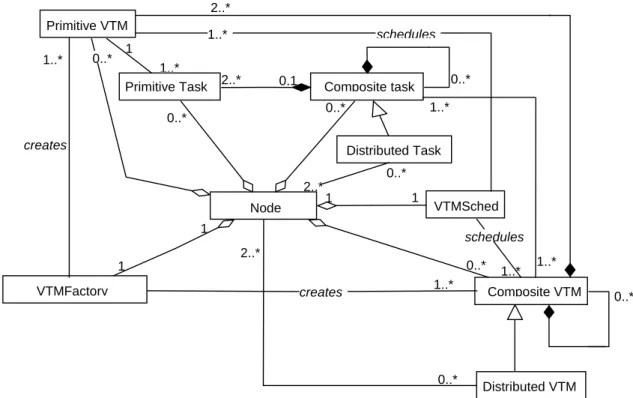
The UML model in Figure 10 illustrates other details concerning the relationship between tasks and VTMs. There is a one-to-one mapping between a task hierarchy and a resource hierarchy. The top-level task of a task hierarchy is directly associated with a composite VTM placed at the top of the resource hierarchy. This composite VTM may encompass various local and/or remote VTMs. Tasks of this kind are composite tasks, which are constituted by a number of sub-tasks. Sub-tasks may be either interleaved or disjoint. In the former case, sub-tasks are associated with
1..* 1 1..* 1..* 1..* 2..* 0..* 2..* 0..* 1 1 VTMFactory 1..* 0..* Composite VTM 1 1 VTMSched 0..* Composite task 0..* Primitive Task Primitive VTM creates Distributed VTM 2..* Distributed Task 2..* Node schedules 1..* 0..* creates schedules 0..* 0..* 0,1 1..*
Figure 10: UML diagram of relationships between Tasks and VTMs.
a single operation invocation sequence whereas in the latter two or more sequences are involved. Sub-tasks that are not further partitioned are called primitive tasks and are only related to a single node. However, distributed tasks involve two or more nodes. It should be noted that sub-tasks may also be composite and even distributed. Similarly, VTMs not containing other VTMs as lower-level resources are named primitive VTMs. Hence, the bottom-levels of a task hierarchy consist of primitive tasks which are associated with primitive VTMs. Primitive VTMs are then defined according to the specific platform characteristics of the node of residence. Moreover, composite VTMs are involved with more than one local task and distributed VTMs include two or more nodes. Importantly, distributed VTMs may recursively encompass other distributed VTMs. Finally, VTM schedulers and VTM factories are defined on a per-node basis.
3.3.3 Task graph configurations
A task graph is a directed graph in which an operation invocation sequence (i.e. a task) is represented in terms of components, component interfaces and component interface operations. Different from component configurations, task graphs define the specific interface operations a task path goes through. There is a great vari-ety of the task graph configurations that can potentially exist. An example of this complexity is the fact that several tasks may be defined over the same component configuration path. Since an interface may include several operations, different tasks may run through the same interfaces by accessing different operations. Moreover, different tasks may even go across the same operations when the same component configuration is used for different purposes (e.g. marshalling video streams and marshalling audio streams). Therefore, components, interfaces, and operations may
participate in more than one task at the same time. Furthermore, the transition from one task to another one is an important issue that contributes to define how task graphs are interconnected. Such transitions are carried out by task switching points. Interestingly, a task switching point corresponds to a change in the under-lying resource pool to support the execution of the task that has come into play. A task switching point is essentially defined as a triplet including a component, an interface, and an exported operation. Imported operations are not used for defining these points for the sake of simplicity. It is only needed one point in the interaction path of two components to define a task switch. This point could be defined in either side of the interaction, however, defining it in the exporter side is more natural as this side is in charge of attending requests.
b) multiple task switching point a) single task switching point
task_n Task point definitions
m_x m_x m_x t_z
. . .
. . .
t_y m_x m_x t_k. . .
. . .
t_y t_i t_x t_z if t_y t_k if t_i m_xTask point definitions
Figure 11: Types of Task Switching Points.
There are two types of task switching points as depicted in Figure 11. A single task switching point, depicted in Figure 11(a), can only switch to a single task whereas a multiple task switching point may switch to two or more different tasks, as shown in Figure 11(b). The former maps a switching task point to a single task. As an example of a single task switching point consider a protocol stack in which each layer is associated with a different task. Hence, when going from one layer to the adjacent one a task switch takes place. In contrast, a multiple task switching point selects, from a set of tasks, the task to switch according to the current task. To accomplish this, ”If” statements are used to define the possible options within a task point. As an example of a multiple-task switching point, consider a task graph of a video stream connection va which includes a filter component bound to a
compressor component and these components are part of task ty and tz respectively.
Similarly, there is another video stream connection vb that uses the same instances
for the both the filter and the compressor, although they are associated with tasks ti and tk respectively. Thus, the compressor will switch to task tz if the filter was
executed as part of task ty, otherwise it will switch to task tk.
3.4
TBMAC API
The TBMAC API can be divided into a number of distinct parts:
1. Initialisation