University of Évora
ARCHMAT
(ERASMUS MUNDUS MASTER IN ARCHaeological MATerials Science)
Mestrado in Arqueologia e Ambiente (Erasmus Mundus - ARCHMAT)
Application of Laser Technologies in the Restauration of
Stained Glass
Xiang Zhang (38424)
Professor Doctor Xermán de la Fuente
Institute of Materials Science of Aragon
Co-supervisor
Professor Doctor Luis Alberto Angurel Lambán
Institute of Materials Science of Aragon
Co-supervisor
Professor Doctor Maria Pilar Alonso Abad
University of Burgos
Co-supervisor
Professor Doctor Nicola Schiavon
University of Évora
University of Évora
ARCHMAT
(ERASMUS MUNDUS MASTER IN ARCHaeological MATerials Science)
Mestrado in Arqueologia e Ambiente (Erasmus Mundus - ARCHMAT)
Application of Laser Technologies in the Restauration of
Stained Glass
Xiang Zhang (38424)
Professor Doctor Xermán de la Fuente
Institute of Materials Science of Aragon
Co-supervisor
Professor Doctor Luis Alberto Angurel Lambán
Institute of Materials Science of Aragon
Co-supervisor
Professor Doctor Maria Pilar Alonso Abad
University of Burgos
Co-supervisor
Professor Doctor Nicola Schiavon
University of Évora
Co-supervisor
JURY MEMBERS
President: Cristina Dias Examiner: Emma Angelini Supervisor: Nick Schiavon Partner Member: Federico di Rita
i
ACKNOWLEDGEMENTS
I wish to thank first of all Professor Xermán de la Fuente and Professor Luis Alberto Angurel Lambán for guiding me through the knowledge and experience in the field of lasers. I would like to thank most especially Professor Luis Alberto Angurel Lambán, who modified my thesis carefully and guided me through the difficulties I faced during the writing process.
I would like to thank Professor Maria Pilar Alonso Abad for the introduction to the background about the history, fabrication, deterioration and restoration of stained glass and for providing the stained glass sample on which this study wasperformed.
I would also like to express my gratitude to Professor Nicola Schiavon for giving me opportunity to work on this project and also for his trust, patience and understanding.
As well, I would like to mention my colleagues Alejandro Montón Zarazaga, Qiaojun Wu and Wei Shao, who have helped me and supported me in this study.
I would like to express gratitude to the Education, Audiovisual and Culture Executive Agency (EACEA) of the European Commission for rewarding me with a scholarship to attend the Erasmus Mundus Master in Archaeological Materials Science, and to the coordinators and professors participating in ARCHMAT project.
As well, I thank my fellow classmates from ARCHMAT for their friendship and constant support, and for all the fun we have had in the last two years.
Last but not least, I wish to thank my friends and family, without whose encouraging words and unfailing support, I would never have got this far.
ACKNOWLEDGEMENTS ... i
LIST OF FIGURES ... iv
LIST OF TABLES ... vi
ABSTRACT ... vii
RESUMO ...viii
AIMS AND OBJECTIVES ... ix
CHAPTER 1: LASERS IN STAINED GLASS RESTAURATION ... 1
1.1.- Stained glass windows ... 1
1.1.1.- Materials and fabrication techniques ... 1
1.1.2.- Producing a window from start to finish ... 7
1.2.- Pathologies and restoration methods ... 7
1.2.1.- Pathologies ... 7
1.2.2.- Restoration methods ... 12
1.3.- Laser cleaning ... 15
1.3.1.- Laser cleaning in conservation ... 15
1.3.2.- Principles of laser conservation ... 16
1.3.3.- Laser cleaning parameters ... 18
CHAPTER 2: EXPERIMENTAL METHODS ... 21
2.1.- Laser systems ... 21
2.1.1.- UV sub-nano laser ... 21
2.1.2.- n-IR sub-nano laser ... 21
2.2.- Modes in laser processing ... 22
2.2.1.- Beam scanning, continuous mode ... 22
2.2.2.- Burst mode ... 23
2.2.3.- Bit-map mode ... 24
2.3.- Characterization techniques ... 24
2.3.1.- Confocal microscopy ... 24
2.3.2.- Portable optical microscopy ... 25
CONTENTS
iii
2.3.3.- Scanning electron microscopy ... 25
2.4.- Materials ... 26
2.4.1.- Sample of historical stained glass ... 26
2.4.2.- Samples of commercial modern glass ... 27
CHAPTER 3: IDENTIFICATION OF ABLATION THRESHOLD IN COMMERCIAL MODERN GLASS ... 28
3.1.- Effect of using the UV laser to process brown industrial glass ... 28
3.2.- Effect of using the UV laser to process transparent industrial glass ... 32
3.3.- Effect of using the n-IR laser to process industrial glass... 35
3.4.- Elimination of surface cracks in window glass ... 36
CHAPTER 4: DEVELOPING LASER PROCESSES TO TREAT LOCALISED AREAS ... 37
4.1.- Developing a system to define areas where laser treatment has to be performed ... 37
4.2.- Example with a stained glass sample ... 43
CHAPTER 5: CHARACTERIZATION OF THE MODIFICATIONS THAT LASER TREATMENTS INDUCE IN STAINED GLASS ... 46
CONCLUSIONS ... 54
LIST OF FIGURES
Fig. 1.1.1 Schematic representation of a grisaille paint layer ... 4
Fig. 1.2.1 A simplified mechanism of the corrosion of glass ... 10
Fig. 1.3.1 Representation of energy redistribution in laser-material interaction ... 17
Fig. 2.1.1 Left: photograph of the ultraviolet laser system; Right: calibration curves of laser power against frequency for different electric current intensities ... 21
Fig. 2.1.2 Left: photograph of the near-infrared laser system; Right: calibration curves of laser power against frequency for different electric current intensities ... 22
Fig. 2.2.1 Different scanning strategies adopted in this study ... 23
Fig. 2.4.1 Photographs of the stained glass sample ... 26
Fig. 2.4.2 Photograph of the commercial modern glass samples ... 27
Fig. 3.1.1 Photograph of the bottle after laser treatment ... 29
Fig. 3.1.2 Images obtained with confocal microscope of irradiation regions ... 30
Fig. 3.1.3 Image obtained with confocal microscope of irradiation region 10 ... 30
Fig. 3.1.4 Images obtained with confocal microscope of irradiation regions ... 31
Fig. 3.1.5 Image obtained with confocal microscope of irradiation region 6 ... 31
Fig. 3.2.1 Photograph of the transparent glass recipent after laser treatment ... 32
Fig. 3.2.2 Images obtained with confocal microscope of irradiation regions ... 33
Fig. 3.2.3 Images obtained with confocal microscope of irradiation regions ... 34
Fig. 3.2.4 Images obtained with confocal microscope of irradiated regions treated using the lowest fluence value with 1 pass (a) or 5 passes (b) ... 34
Fig. 3.2.5 Confocal images showing the topography of the two images presented in Fig. 3.2.4. ... 35
Fig. 3.3.1 Photographs of both industrial glass samples showing the effect of the n-IR laser ... 36
Fig. 3.4.1 Scratched window glass after being treated with a CO2 laser ... 36
Fig. 4.1.1. Exemplary black and white image, which defines the bitmap scanning .... 38
Fig. 4.1.2. Photographs of the transparent stained glass sample taken with optical microscope ... 38
v Fig. 4.1.3. Images obtained with confocal microscope showing the topography of the
irradiation region ... 39
Fig. 4.1.4 Selective removal of black paint from glass ... 41
Fig. 4.1.5. Photograph of the aluminum foil under the glass after laser treatment ... 42
Fig. 4.2.1 Optical microscopic images showing the surface morphology of the sample after different number of laser passes ... 44
Fig. 4.2.2 SEM images showing the surface morphology ofthe sample after different number of laser passes ... 45
Fig. 5.1.1 A small corner fragment was cut from the stained glass sample ... 46
Fig. 5.1.2 Photographs of the corner fragment taken with optical microscope ... 47
Fig. 5.1.3 Image taken with FESEM of the irradiation regions I and II ... 48
Fig. 5.1.4 Higher magnification FESEM images of each zone ... 51
Fig. 5.1.5 Images taken with FESEM of the irradiation region I zone 6 showingthe defects created on the glass surface ... 52
Fig. 5.1.6 Images taken with FESEM of the irradiation region III ... 52
LIST OF TABLES
Table 3.1 Parameters used in the laser treatments performed on irradiation regions .. 29
Table 3.2 Parameters used in the laser treatments performed on irradiation regions .. 33
Table 4.1 Parameters used in the selective laser cleaning performed on stained glass sample ... 44
Table 5.1 Parameters used in the laser treatments performed on irradiation regions I-IV ... 47
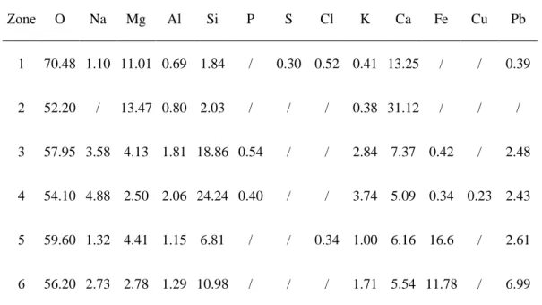
Table 5.2 Results of EDS analysis for irradiation regions I and II (at%) ... 49
Table 5.3 Results of EDS analysis for irradiation region I zone 3 (at%) ... 51
Table 5.4 Results of EDS analysis for irradiation region I zone 6 (at%) ... 52
vii
ABSTRACT
In this work, an attempt is made to go a step further in application of laser technologies in the restauration of stained glass. Several cleaning experiments have been conducted by two sub-nanosecond pulsed lasers (a UV laser and a n-IR laser), and materials taken for this study were a 16th century stained glass sample from the
Cathedral of Cuenca and some samples of commercial modern glass. Parameters affecting the cleaning outcomes were studied and the applicability of the selective cleaning method for stained glass restoration was explored. The treated samples were analyzed by optical microscopy, confocal microscopy, scanning electron microscopy and energy dispersive X-ray spectroscopy. Results showed that the alteration and ablation phenomena varied considerably depending on the selected laser parameters, as well as on the chemical compositions (thus also the colors) of the glass samples. Selective laser cleaning proves to be a feasible technique for relatively precise and controllable cleaning of cultural heritage stained glass, but caution must be taken in its application.
RESUMO
Aplicação de tecnologias laser no restauro de vitrais
Neste trabalho, tenta-se dar um passo adiante na aplicação de tecnologias laser na restauração de vitrais. Vários experimentos de limpeza foram conduzidos por dois lasers subnanosegundos pulsados (um laser UV e um laser n-IR), e os materiais tomados para este estudo foram uma amostra de vidro colorido do século XVI da Catedral de Cuenca e algumas amostras de vidro comercial moderno. Parâmetros afetando os resultados de limpeza foram estudados e a aplicabilidade do método seletivo de limpeza para restauração de vitrais foi explorada. As amostras tratadas foram analisadas por microscopia ótica, microscopia confocal, microscopia eletrônica de varredura e espectroscopia de energia dispersiva de raios-X. Os resultados mostraram que os fenômenos de alteração e ablação variavam consideravelmente, dependendo dos parâmetros do laser selecionados, bem como das composições químicas (e também das cores) das amostras de vidro. A limpeza seletiva a laser demonstra ser uma técnica viável para a limpeza relativamente precisa e controlável de vitrais do patrimônio cultural, mas deve-se tomar cuidado em sua aplicação.
ix
AIMS AND OBJECTIVES
The cleaning process for stained glass has to consider the effectiveness of the treatment but also the potential damage for the substrate. In the last two decades, some studies of laser cleaning applied for stained glass windows have been performed and promising results have been obtained. However, it is important to explore if the new developments in laser technology can be used to overcome the problems that limit its application in the restauration of stained glass. Nowadays, it is possible to combine an ultrashort pulse laser with a galvanometric mirror scanner system which provides precision and reproducible scanning of the laser beam on the sample surface. This is the laser system used in this study. In this work selective laser cleaning will be performed on stained glass to determine the feasibility of picosecond lasers for glass restoration.
The main purposes of this study are to:
⚫ revise bibliography about stained glass history, fabrication, deterioration and restoration;
⚫ investigate the influence of relevant parameters in laser cleaning;
⚫ conduct experimental research on selective laser cleaning of crust and deposit present on stained glass, and explore the applicability of the cleaning method for stained glass restoration;
⚫ analyze the modifications that laser treatments induce in cultural heritage stained glass.
CHAPTER 1: LASERS IN STAINED GLASS RESTAURATION
1.1.- Stained glass windows
Stained glass windows are composed of shapedpieces of colored glass, held together in a lead network and enhanced with the surface application of a painted pigment (Bernardi et al., 2006; Brown and Strobl, 2002; Romich et al., 2003). Serving as light filters and iconographic supports, the stained glass windows are a critical element both in the religious and secular architecture (Basso et al., 2009).
1.1.1.- Materials and fabrication techniques
Colored glass pieces
It is obvious that the predominant component of a stained glass window is glass (Brown and Strobl, 2002). Most of what is known about ancient colored glass manufacturing technology stems from a medieval technical manual. A Benedictine monk named Theophilus wrote amanuscript entitled De diversis artibus (On Divers
Arts) around 1100, in which he described the full process to make sheets of colored
glass and to fabricate a window (Kleiner Fred, 2014). According to the author, materials for making ancient glasses were washed river sand (which is silica) and beechwood ash (which is potash, an alkali). The ingredients were mixed together in clay pots and then placed in a furnace, heated “for a night and a day”. The heating and fusing of these materials combine them together to form liquid glass (Raguin, 2013; Schalm et al., 2007). Another glassmaking text, found in the work entitled De artibus romanorum (or De colouribus et artibus romanorum), advised the addition of powdered metallic oxides to the ash and sand to produce different colors of glass. The text wasattributed to a monk Heraclius who presumably lived in the thirteenth century (Benton, 2009; Charleston, 1960; Royce-Roll, 1994).
Although the process of making stained glass has evolved both regionally and over time, the basic steps and main ingredients remain unchanged. These ingredients
2 forms the vitreous network of glass, requires a very high temperature in order to melt. So, alkali was introduced as the flux to decrease the melting temperature. The fluxes were either plant-based (beech or fern ash) or mineral-based (natron) and, depending on the nature of the material, enriched either in potash or in soda (Raguin, 2013; Weaver et al., 2016). The color was achieved by the addition of various metallic oxides during the fusing process: cobalt makes blue; copper makes red; lead or chromium makes yellow; chromium or copper makes green; manganese or nickel makes violet; and iron or manganese makes brown or black. Meanwhile, the firing atmosphere should be controlled because the redox condition of the atmosphere in the furnace chamber also influences the color produced (Raguin, 1988; Royce-Roll, 1994; Sterpenich and Libourel, 2001).
This kind of stained glass is additionally referred to as pot metal glass, the word “metal” is used due to the coloringmetallic oxides added to the “pots” that held the melted glass (Benton, 2009). The pot metal glasses were more or less colored throughout with a single color. To create two colors on a single piece, or to retain the translucency in glass that contains strong light absorbing colorants, artisans began to exploit double-layered, or flashed, glass in the fourteenth century (Brown and Strobl, 2002; Marks, 2006). Flashed glass was produced by fusing a thin, concentratedlayer of a previously colored glass onto the surface ofanother piece of clear glass or colored glass of a different hue (Benton, 2009). After cooling, the surface colored layer can be abraded away or acid-etched to reveal the color of the base (Raguin, 1988; Raguin, 2013). A typical example is ruby glass. The surface of the glass is coated with a thin layer of ruby (red) and the base is white, pale yellow, grey or green according to the required tint(Maurice Drake, 1928; Van der Snickt et al., 2016).
Traditionally, there were two major methods to form sheets of glass. The first method was called the crown method. In the process a bubble was blown from a globule of molten glass and transferred from the blowpipe to an iron pontil. The
glassblower then held the glass bubble in front of the glory hole of the furnace and opened it up by twirling or spinning. With continuous spinning the material would form a flattish circular disc as a result of the centrifugal force. The piece in the center with the mark where the pontil was attached was called the “crown”, giving the name to this technique (Malcom, 1990). The glass produced by this method tended to be relatively heavy and thick. The second method was called thecylinder, or muff, technique. In this method,the molten glass was blown into the shape of a long cylinder, the ends of which were pinched off. It was then reheated and cut lengthways with a hot iron. The heat caused the glass to relax and in the kiln it would be opened out to form a flat rectangle sheet. The resulting sheets were lighter, thinner, and usually larger than those produced by the crown method (Raguin, 1988; Raguin, 2013; Vilarigues et al., 2011). Whichever process was used, it is essential to place the finished flat sheet in an annealing furnace to cool it slowly, since the glass cracks if subjected to sudden temperature changes (Marks, 2006; San Casciani, 1989).
The discs or sheets of glass that were yielded by these techniques needed to be cut to the shapes required for incorporation into a panel of stained glass window. Medieval artisans shaped the glass pieces with a hot iron tool. They ran the hot iron along the proposed line of fracture slowly, followed by tracing the pattern with a cooler element, such as water or saliva,thus causing the glass to crack along the line. Then they snapped or broke the glass into shape. The roughly shaped edges can be trimmed by nibbling bits of glass off the rim with a hook-shaped metal tool (called a grozing iron) (Arnold, 2014; Kibler and Zinn, 2017; Raguin, 2013). The diamond tip cutter, which allowed for more precise cutting, began to replace the hot iron in the fourteenth century, and has in its turn been superseded by the modern glasscutter in the seventeenth century (Benton, 2009; San Casciani, 1989; Wigelsworth, 2006).
4 Painting on Glass
Once the necessary pieces of colored glass had beencreated, the painting took place. Most of the stained glass from the medieval and Renaissance periods were painted (Raguin, 2013; Wigelsworth, 2006). Three different kinds of glass paints can be distinguished. Grisaille has been used to color glass panes in shades of gray and brown since the ninth century. Silver stain was introduced to color glass in bright yellow in the early fourteenth century. Finally, various colored enamel paints were developed in the sixteenth century. Since then, many colors could be painted on a single glass piece (Benton, 2009; Schalm et al., 2009).
1Fig. 1.1.1 Schematic representation of a grisaille paint layer(Schalm et al., 2003)
The grisaille (French for “greyness”) is brownish or blackish vitreous paint used for indicating the details of faces, drapery folds, or background patterns, usually on the interior side of the stained glass windows (Hall, 2007; Kibler and Zinn, 2017; Raguin, 1988). It can be applied either as a thick, opaque line or as a thin, uniform layer. The grisaille paint was made from powders of finely ground lead silicate glass (fusible at a lower temperature compared with the substrate) mixed in the right proportions with pigments (metallic oxides) and organic binding agents. This mixture was usually applied with paint brushes. To affix the grisaille paint, the glass pieces had to be fired in a furnace at temperatures below the transition temperature of the substrate glass. The lead glass grains melt during firing and bonded the pigment grains to the base glass (Becherini et al., 2008; Benton, 2009;
Carmona et al., 2006; Schalm et al., 2003; Schalm et al., 2009). A schematic representation of the grisaille glass paint is shown in Fig. 1.1.1
Silver stain, also called yellow stain, is the only true staining method in stained glass. Glass artisans adopted this technique to achieve a permanent yellow color, which was used widely to color hair, drapery and small details of clothing. The staining method considerably decreased the need to cut and join small pieces of different colored glass together with lead strips. This technique involves, first, applying silver compounds in a carrier medium (such as clay or ochre) onto the exterior surface of the glass. Next,heating the glass panels at temperatures below the glass softening range (Kibler and Zinn, 2017; Raguin, 2013). The heating process allows silver ions to penetrate into the substrate glass, exchange with the alkali ions in the glass, and be reduced to metallic silver if they react with other metastableions (such as Fe2+, As3+ and Sb3+) or non-bridging oxygens, which serve as electron donors
(Fernandes et al., 2008; Findakly, 1985). Metallic silver aggregates precipitate as spherical metallic particles. After heating,the carrier medium is removed from the glass, revealing the characteristic yellow color produced by silver particles. The stain process can create a range of hue from lemon yellow to fiery orange, depending on the composition of the base glass, and the number, shape, particle size and its distribution of the silver particles (Jembrih-Simbürger et al., 2002). Silver stain could also be used to create the green color when it is applied onto blue glass (Brown and Strobl, 2002).
Enamel is a vitreous paint created from powdered glass and colored metallic oxides. The introduction of various colored enamels in the sixteenth century was a significant development in stained glass window technology. Since a vast range of colors could now be painted on a single glass piece, windows were no longer composed of small pieces of glass, each possessing its own individual color, but were made of larger pieces of light-colored glass treated as a painter’s canvas
6 melting together a flux (a powdered, low melting lead glass) with a coloring substance (metallic oxide). The molten glass was quickly cooled down and ground into a fine powder,then mixed with a sticky medium such as water-based gum or oil in order to obtain a paste paint that can be applied onto a glass pane. The painted glass was subsequently fired and cooled slowly. The enamel transformed into a thin homogeneous glass layer which adhered to the substrate and turned a transparent color during the process (Attard-Montalto and Shortland, 2015; Jones and Matthews-Jones, 2016; Schalm et al., 2009).
Lead cames and metal framework
The second major structural element in a stained glass window is lead. The fired pieces of glass were joined together with flexible strips of lead commonly called “cames”. In the Middle Ages, lead cames were cast in molds. From the late sixteenth century, cames were made by extruding the lead through a mill (Brown and Strobl, 2002; Raguin, 2013). The H-shaped lead cames were grooved on either side to accommodate the edges of the inserted glass pieces. The lead between the pieces of glass is thinner and has wider flanges in late windows than in early windows (Benton, 2009). Joints of the lead cames were soldered on both sides and putties were forced between the glass and came flange to make a watertight seal. In addition to holding the assembled pieces of glass together, the lead also separated the colors and formed an integral part of the design (Hall, 2007; Kibler and Zinn, 2017; Kleiner Fred, 2014). The completed panel was placed into a metal framework which was referred to as an armature, and then fixed into the window opening. Additional reinforcement was provided by iron bars and stone tracery. An iron bar grid set in the frame was used to give the panel structural rigidity. The iron bars might also be curved to follow the major shapes in the panel so as not to diminish its designed effect. Stone bar or rib supports called tracery were often used on large circular windows (Benton, 2009; Raguin, 1988; Raguin, 2013; San Casciani, 1989).
1.1.2.- Producing a window from start to finish
A stained glass window is created through the collaborative efforts of artisans with different skills (Brown and Strobl, 2002). First, the sketch was drawn full scale by a master designer on a large wooden panel, indicating the exact sizes and shapes of the separate pieces and noting the colors for each region. The design must include some allowance for the thickness of the lead cames (Benton, 2009; Kleiner Fred, 2014). When larger windows were used, the first design would be drawn at a smaller size and then enlarged to a full-scale rendering. Then colored glass sheets were provided by glassblowers and the individual pieces were cut by glassworkers to the required size and shape. Next, painters added details by tracing the design on the wood board through the colored glass. The painted glasses were then heated in a kiln to fuse the paint to the surface (Raguin, 2013). Finally, the glaziers joined the pieces of glass by strips of lead and strengthened the completed window with an iron framework (Kleiner Fred, 2014).
Every component of the stained glass window may yield precious information about the past. When implementing a conservation program, it is required that as much of the original historic fabric as possible is preserved, and all aspects of the window should be taken care of (Brown and Strobl, 2002). Inappropriate repairs and maintenance would induce further deterioration and ultimately result in the loss of heritage significance of the window (Wong, 2016). Repairs can only be carried out after a careful evaluation of the condition of the stained glass window has been performed (Vogel and Achilles, 1993a).
1.2.- Pathologies and restoration methods
1.2.1.- Pathologies
Since their creation, stained glass windows are prone to deterioration due to unfavorable environmental conditions. Three elements of the stained glass
8 windows are susceptible to deterioration: the colored glass itself; the applied paint; and the skeletal structure that holds the glass (Vogel and Achilles, 1993a).
Glass
Glass is the typically brittle material, and its composition makes it highly sensitive to moisture and to atmospheric pollution (Brown and Strobl, 2002). The weathering of stained glass pieces does appear as a consequence of the synergic effect of atmospheric agents and humidity (Carmona et al., 2006). Other factors that contribute to the deterioration process include changes in temperature, microorganisms, meteorological and human induced hazards, and intrinsic factors such as glass impurities and tiny internal fractures. Glass is also quite vulnerable to scratching, cracking or breakage (Godoi et al., 2006; Vogel and Achilles, 1993a).
Crack, breakage and the methods of repair
One of the most common causes of crack or breakage is physical impact. Cracked or missing stained glass pieces are possibly caused by accidents, intentional acts of vandalism, and the failure of lead cames. Cracks can also result from internal stress generated by improper annealing. Windows assembled with long, narrow and angular glass pieces are inherently susceptible to cracking (Wong, 2016). The cause of the cracks can be diagnosed by the crack paths: impact-related cracks typically radiate away from the impact source. Stress cracks caused by inadequate annealing will travel a highly irregular path. When the window is subject to temperature-induced expansion and contraction, mechanical vibration or other stress, the cracks will extend as the contacting glass edges rub against each other. It is, therefore, important to repair cracks in important areas as soon as the fine cracks are detected. Traditionally, cracks were repaired with a “false lead”, a lead flange spliced over a fine crack. Even though the lead conceals the crack, it creates a greater degree of visual intrusion and provides no true bond to the glass (Vogel and Achilles, 1993b). Today, there are two primary types of repair to consider: chemical repair (epoxy glue and silicone glue) and mechanical repair (copper foil)
(Wong, 2016). These methods differ from each other in strength, visual effect and reversibility, and the appropriate technique should be determined on a case-by-case basis (Vogel and Achilles, 1993a).
Copper foil is generally the best option for less significant areas. The thin copper tape can produce a strong repair when it is applied along each side of the glass break and soldered. Copper foil has a negligible aesthetic impact and is totally reversible. Since heat is required, this kind of repair is not appropriate for unstable glass. Epoxy glue is often used in important painted areas. The synthetic, colorless adhesive produces a very strong repair and can even be tinted to improve the legibility of the stained glass (Raguin, 1988; Wong, 2016). The drawback of epoxy glue is that it is the least reversible of these techniques and will deteriorate in sunlight. In contrast, silicone glue is easily reversible and not affected by UV light, temperature or humidity. But this repair method has the lowest strength and is easily detectable because silicone refracts light differently from glass (Vogel and Achilles, 1993a).
Original glass should be retained and preserved wherever possible, but sometimes the only option is to replace the broken or missing glass. Replacement glass should closely match the existing pieces with the support of evidence and records. To prevent any confusion in the future, the new glass pieces should be scribed at an inconspicuous position (such as the edge under the came) with the date (Vogel and Achilles, 1993a; Wong, 2016).
Dirt and corrosion
A variety of degradation phenomena take place on the stained glass windows (Römich and Weinmann, 2000). Dirt, grime and soot can build up on the stained glass from pollution and smoke. The use of incense or candles in churches can deposit carbon layers on the glass. All these deposits can substantially reduce the
10 amount of light passing through the windows and make them muted and lifeless (Vogel and Achilles, 1993a).
Corrosion (weathering) of glass may be the result of the attack by water (humidity, rain), chemicals (acidic pollutants), or possibly biological agents (Römich et al., 2003; Raguin, 1988). In addition, glass composition and previous restoration campaigns may also influence the weathering process (Murcia-Mascarós et al., 2008; Römich and Weinmann, 2000). Generally, a 3-stage system can be established between the ambient atmosphere, the adsorbed water layer and the original glass surface (Godoi et al., 2006; WoisetschlaÈger et al., 2000). Fig. 1.2.1 presents a simplified mechanism for the corrosion process.
2
Fig. 1.2.1 A simplified mechanism of the corrosion of glass (Melcher et al., 2010)
(a) Glass corrosion starts with a clean and unweathered surface. (b)A water film is adsorbed on the glass surface, enabling the exchange of ions between the ions (H+)from water and the
alkaline ions (K+ and Ca2+) of the glass,which may be enhanced by the presence of acidifying
gases. (c) A leached and hydrogen-enriched layer is formed. (d) Corrosion products remain on the surface of the glass after the water evaporates.
As can be seen from Fig. 1.2.1, a thin water film formed on the glass surface enables an ion exchange process, where the modified cations (K+ and Ca2+) in glass network
are leached out and the hydrogen bearing species from water are incorporated into the silicate structure. Atmospheric pollutants or airborne particulate matters can dissolve in the water layer, leading to a reduction in its pH and an enhanced diffusion of ions. If the product of the concentrations of respective ions exceeds the solubility product of a specific compound, precipitation of this corrosion product takes place (Godoi et al., 2006; WoisetschlaÈger et al., 2000). After the water film evaporates, the corrosion products remain on the glass surface. Their chemical compositions significantly depend on the composition of the glass and the type of the atmospheric pollutants (Melcher et al., 2010). Most of the reported composition of the crusts developed on stained glass windows consists of silica, SO3,
CaO and K2O. Salts with poor solubility which darken the glass are mainly
hydrated silica (SiO2·nH2O), gypsum (CaSO4·2H2O), basanite (CaSO4·1/2H2O),
arcanite(K2SO4), syngenite (K2Ca(SO4)2·H2O), palmierite(K2Pb(SO4)2), anglesite
(PbSO4) and calcite(CaCO3). Soluble nitrates and other soluble carbonates and
sulphates do not form crusts. Crusts consisting of CaCO3, CaSO4 or PbSO4 can
also develop on grisailles (Murcia-Mascarós et al., 2008).
Biodeterioration
As mentioned above, another important factor that enhance corrosion is biodeterioration. The biodeterioration processes on glass happen as the result of the metabolic activities of microbial communities composed mainly of lichens, bacteria and fungi (Marvasi et al., 2009; Schabereiter-Gurtner et al., 2001). The role of microbial communities in the degradation of glass includes both mechanical and chemical destruction. The filamentous growth of fungi and some actinobacteria can cause a mechanical destruction. The adsorption of water could create a leaching environment, enhancing the chemical destruction of the glass. Organic or inorganic acids secreted by microorganisms can cause changes in pH, the leaching of elements from glass and the chelation of special glass components. In summary, biological activity on glass surfaces causes several types of damage, including cracks,
12 corrosion, biopitting and patina formation (Drewello and Weissmann, 1997; Krumbein et al., 1991; Piñar et al., 2013).
1.2.2.- Restoration methods
Glass cleaning
Depending on the state of conservation, the stained glass window is either dismantled or cleaned and repaired in-situ. The cleaning process is one of the most delicate phases of the restoration-conservation work of stained glass. Both slightly-adhered debris and strongly-fixed crusts should be removed from the glass surface to restore the windows’ original iconography and to prevent further deterioration and alteration (Vogel and Achilles, 1993a). Currently, the cleaning of glass surfaces is achieved through various mechanical and chemical methods. The mechanical methods range from bristle brushes to glass-fibre brushes and scalpels. Chemical cleaning methods commonly include the use of water or organic solutions (Delgado, 2016). The choice of cleaning methods and agents depends on the type of deterioration observed, and whether the window has to be dismantled or not.
The least adhered debris can be removed using non-destructive brush. The strongly fixed deposits need to be removed using carefully selected chemical cleaning methods (Murcia-Mascarós et al., 2008). Water alone should be tried first (distilled water is preferable) when cleaning dirt from glass. For the removal of shellac, lacquer, or very stubborn grime, alcohol or organic solvents may be required and must be used only when gentler methods have failed. Aggressive or caustic cleaners, or solutions with pH values in the acidic range or alkaline range should never be used in the cleaning process (Vogel and Achilles, 1993a; Wong, 2016).
Before starting any cleaning work in painted areas, the paint applied to glass should be inspected to make sure it is firmly attached and will not be removed. The loss of paint would cause irreversible damage to the artistic integrity of the stained glass window. The method that shows a high efficiency in removing the dirt or
diminishing the crusts may not be the best one to use because it may also induce damage or long-term risks to the glass or the paint layer (Raguin, 1988).
It is also very important that rather than removing the corrosion deposits down to the bulk glass, the leached glass surface layer (gel layer) belonging to the original substance should remain unaltered during cleaning. The gel layer can protect the glass beneath from further degradation. The same requirement applies to the removal of the bio-layer, which are the result of the microbial metabolism on the glass surface (Delgado, 2016; Römich et al., 2003).
Deterioration and restoration of glass paints
In some cases, glass weathering can cause the alteration of the adhering paint. In other cases the paint itself may deteriorate. Two forms of degradation can be distinguished: degradation can appear as disintegration and pulverization of the glass paint, or areas of paint may maintain internal cohesion but peel or flake off the substrate due to loss of adhesion (Carmona et al., 2009). Two mechanisms govern the deterioration phenomena of glass paint: a chemical mechanism including the corrosion and pulverization of the paint, and a physical mechanism associated with micro-fractures (Becherini et al., 2008). As mentioned previously, the glass piece is again heated in a kiln after the paint is applied. If the firing is improper or the composition of the paint is not appropriate, tensions will arise, leading to detachment of the glass paint (Murcia-Mascarós et al., 2008). Paint failure is commonly caused by incomplete firing (baking the glass either for too little time or at too low a temperature). Some chemical compositions of historical glass paints appear to be unstable. For example the enamels with a high content of K2O and a low content of
PbO and CaO show a relatively fast deterioration (Schalm et al., 2009). Improper steps in the painting process can also produce fragile paint. For instance, the paint may not fuse properly if it is poorly mixed or applied too thick to the glass (Vogel and Achilles, 1993a). In addition to the degradation due to material properties or
14 manufacturing and painting processes, paint on glass is extremely vulnerable to the effects of condensation (Carmona et al., 2009).
Several paint treatments and surface coatings have been developed to consolidate and protect deteriorated paint. Historically, natural wax has been used to achieve the consolidation of unstable paint in some cathedrals (Carroll et al., 1994). In contemporary restoration practices, Paraloid B72 is most commonly used for this application due to its good reversibility. But as an organic material, Paraloid B72 is subject to the environmental impact with time, and thus its long-term stability is limited. In recent years, new materials like sol–gel based consolidants have been proposed for the consolidation of paint on stained glass and received attention by the expert community due to their promising laboratory results (Carmona et al., 2009). If serious paint failure occurs in a prominent area of the window, a coverplate of thin, transparent glass can be painted on the backside with the reverse image of the missing features and placed over the original. The coverplates should be mechanically attached to the window, rather than laminated, so they can be removed easily later if necessary (Vogel and Achilles, 1993a).
Deterioration and restoration of the skeletal structure
Another common threat to stained glass windows is deterioration of the skeletal structure. The structure consists of frame members such as metal frames or stone traceries that provide structural rigidity to the glass panels, and assembly materials such as lead cames that hold the pieces of glass together. Metal frames and saddle bars can corrode over time and quicken the deterioration of the glazing and sealants. Stone traceries can fracture and spall, which contributes to structural failure of the window. Maintenance of the frame members at regular intervals is necessary to prevent further deterioration. This involves regular caulking and periodic reglazing. Deteriorated frames should be repaired where necessary by removing the degraded sections and splicing in new ones. Stained glass windows should only be dismantled when they need to be flattened, reputtied, reinforced, or releaded.
Occasionally, leading patterns was designed with inadequate bracing, this also results in structural failure (Vogel and Achilles, 1993a). In other cases, the arrangement of support is adequate, but the solder joints may be weak and fractured, and the putty may be deteriorated or have fallen out from under the lead flange (Raguin, 1988; Wong, 2016). When the panel loses stability, there is a chance the stained glass could sag, bulge and eventually even fall out from vibration or wind pressure. Windows should be removed from the opening and flattened with extreme care when the sagging and bulging has reached the precarious level. The flattening process also provides a good opportunity to resolder the joints and reputty the windows. Leadcamesare subject to corrosion from moisture and humidity, and fatigue failures associated with thermal expansion and contraction (Sloan, 1991). As an integral component of the stained glass window, the lead came should only be replaced if it is exhausted beyond repair. Releading a window is very time consuming and expensive. The individual pieces of glass need to be removed from the lead cames, the old putty needs to be cleaned from each glass piece, and then all the pieces need to be rejoined accurately. It is essential to retain the historical accuracy by following the lines, profile and width on the rubbing of the original leadwork (Vogel and Achilles, 1993a; Wong, 2016).
1.3.- Laser cleaning
1.3.1.- Laser cleaning in conservation
Research on the topic of laser cleaning in conservation began in the 1970s, when John F. Asmus performed a series of studies on the use of lasers in cleaning altered marble, metal, and terracotta (Asmus et al., 1973). Asmus’s experiments revealed practical applications of the novel approach and its possible future developments. However, laser cleaning did not experience a widespread growth in the field of artwork conservation because of the technological limits and high costs at that time. The performance of laser devices increased markedly during the eighties. But the costs remained high and the productivity gap between laser cleaning and traditional
16 cleaning techniques was large. In this context, conservation community did not realize the full potential of this new cleaning technology (Siano, 2008). In the early nineties the situation drastically changed as a result of successful collaborations between research institutes and continuous support from European Framework Program together with various national program for the development of new methodologies and technologies for the conservation of cultural heritage. In the UK, M. I. Cooper and D. C. Emmony with the conservation support of J. Larson, conducted detailed experimental investigations on the use of laser cleaning to preserve limestone and marble sculpture (Cooper and Larson, 1996; Cooper et al., 1995). D. C. Emmony and P. Pouli have also investigated laser-induced discoloration effects on medieval pigments (Pouli et al., 2001). During 1992-1995, led by Dickmann at the Lasercenter Fachhochschule Münster and Römich at the Fraunhofer-Institut für Silicatforschung in Germany, two independent feasibility studies were carried out on laser removal of organic and inorganic corrosion from stained glass (Romich et al., 2003). Their work played a crucial role in the further development of the field (Fotakis et al., 2006). In 1995,an international conference on lasers in the conservation of artworks (LACONA) was held in Crete, Greece. For the first time restorers and scientists were brought together to discuss the potential of lasers in art conservation. Since then this field has gained enormously in importance. The creation of LACONA and subsequent ten LACONA gatherings, held every two years, reveal signs of maturation of laser technology in the conservation field (Asmus, 2003; Nimmrichter et al., Sept. 21–25, 2005).
1.3.2.- Principles of laser conservation
The word LASER is an acronym termed Light Amplification by Stimulated Emission of Radiation. Because of the unique properties, such as monochromaticity, directionality and coherence, laser has been considered a technological advance in all its areas of application (Mahamood, 2018). When laser interacts with material surface, the incident radiation may be absorbed, transmitted, reflected and scattered (Pouli, 2000). The amount of each type of
energy is determined by the parameters of the laser radiation and absorption properties of the material. Scattering and absorption contribute to attenuation and spatial diffusion of the laser energy (Hrnjić, 2015). A qualitative representation of the energy redistribution in irradiated solids is shown in Fig. 1.3.1.
3Fig. 1.3.1 Representation of energy redistribution in laser-material interaction (Siano, 2008)
(a) absorbing material; (b)diffusing material; (c) composite situation of an absorbing layer on a diffusing substrate (Er, Ea = reflected and absorbed energies)
The absorption of laser radiation can lead to ablation, which is the main phenomenon involved in laser cleaning. Ablation involves the ejection of material from a laser irradiated surface, sometimes accompanied by the formation of a plasma when intense laser irradiation is used (Cooper, 1994). Three main types of interactions may occur during the process of laser ablation, which are photothermal, photochemical, and photomechanical interactions. The exact interaction mechanisms depend on the laser parameters and on the physical and chemical properties of the target material. The thermal properties of the material (i.e. thermal conductivity and heat capacity) are important parameters to evaluate both the volume of the material affected by laser irradiation and the maximum temperature reached in the process. Strong absorption of energy leads to rapid heating of the material, followed by its thermal expansion and the emission of a shock wave, which causes ablation at the surface (Koh, 2005). The minimum energy density required to achieve ablation is called the ablation threshold. When the ablation threshold of the material to be removed is lower than that of the original
18 substrate, the removal process can be performed within safe parameters. That is, the energy density deposited onto the sample surface is sufficient to clean the contaminants but not enough to damage the substrate material. The cleaning is described as a “self-limiting” process in this case (Hrnjić, 2015; Mateo et al., 2005).
1.3.3.- Laser cleaning parameters
When laser cleaning technique is employed to remove contaminants from the surfaces of artworks, proper parameters should be selected for efficient and safe cleaning. At low energy densities the laser irradiation may not be enough to completely remove contaminants. While the use of overly aggressive parameters can result in over cleaning and consequent damaging of the artefacts (Koh, 2005). This section discusses the main controllable parameters that can affect the performance of laser cleaning, including wavelength, pulse duration, energy density and so on.
An important parameter associated with laser cleaning is the wavelength of the laser system. As the reflectivity and absorption coefficient of contamination and substrate material varies with the wavelength of the incident laser, different wavelengths will result in different cleaning efficiencies. The choice of an appropriate wavelength is essential for effective cleaning. Generally, the wavelength that offers a higher absorptivity in the unwanted surface layer than in the underlying substrate is preferred (Hrnjić, 2015; Quintana, 2016).
Once the laser is activated, the emission of laser energy may be continuous (cw operation) or pulsed. A continuous wave laser emits a laser beam with a constant power and intensity over the entire time interval. Whereas, a pulsed laser generates laser pulses at varied rates, with an on time when energy is released (pulse duration or pulse width) and an off time when there is no energy released. When energy is emitted in very short time, it results in high peak powers and peak intensities, which is more suitable for ablation of materials. The laser pulse duration is another
important parameter affecting the performance of laser cleaning. In principle, the shorter the pulse duration, the higher the peak power intensity made available, and the stronger the shock wave generated in the process (Millis and Levine, 2013; Pradhan et al., 2017; Rea, 2004). With the development of laser technology, short pulse durations of nano (10-9), pico (10-12) or femto (10-15) -second can be obtained
(Fotakis et al., 2006). The ultrashort pulse laser offers several advantages. When its pulse duration is less than the thermal conduction time of the sample, ultrashort pulse laser can generate an almost non-thermal interaction in the ablation process, allowing precise and thermal-damage-free removal of material (Hrnjić, 2015; Hu et al., 2010; Kerse et al., 2016). Besides the single pulse effect, however, it is also important to take into account the cumulative heating effects from successive pulses, which would occur if the repetition rate (the number of emitted pulses per second) is too high to allow a complete thermal relaxation of the irradiated material within the time interval between two consecutive pulses (Siano, 2008; Siano and Salimbeni, 2001).
Once the correct wavelength and pulse width have been selected, laser fluence and irradiance, which play a central role in the ablation process, should be considered. Fluence, also referred to as energy density(Rubahn, 1999), is given by the following equation:
𝐹 = 𝑃
𝑓𝑟𝑒𝑝𝐴
where P is the average output power of the laser, frep is the repetition rate and A is the
spot area. It has to be noted here that the laser pulse duration is not involved in this equation, which could create some ambiguity when comparing fluence values of lasers with different pulse durations. When evaluating damage thresholds for laser cleaning, it is more appropriate to use irradiance, which is calculated as:
20
𝐼 = 𝑃
𝑓𝑟𝑒𝑝𝐴𝑡𝑝
= 𝐹 𝑡𝑝
where tp is the pulse duration (Rodriguez-Navarro et al., 2003). Also, it is expected
that using the same irradiance value will guarantee reproducible results in the treatment of artefacts (Hrnjić, 2015).
CHAPTER 2: EXPERIMENTAL METHODS
2.1.- Laser systems
2.1.1.- UV sub-nano laser
In this study two laser systems were used. The first one was an ultraviolet laser (Rofin-Sinar PowerLine Pico 10-355) with a wavelength of 355 nm. The maximum output power is 3 W and the laser was operated with a range of frequencies between 200 and 800 kHz. The diameter of the laser beam is 17 µm and the pulse duration is 300 ps. The laser power was controlled by changing the electric current from the power source. The UV laser system and the calibration curves of laser power against frequency for different electric current intensities are shown in Fig. 2.1.1, indicating that the maximum power is reached at 300 kHz.
4Fig. 2.1.1 Left: photograph of the ultraviolet laser system; Right: calibration curves of laser power
against frequency for different electric current intensities
2.1.2.- n-IR sub-nano laser
The second laser system was a near-infrared laser (Rofin-Sinar PowerLine Pico 10-1064) with a wavelength of 1064 nm, a pulse duration of 800 ps and a maximum output power of 8 W. The pulse repetition rate can be modified between 200 and 800 kHz and the spot diameter of the laser beam is 25 µm. Fig. 2.1.2 shows the n-IR laser system and the calibration curves of this laser. In this case, at frequencies higher than 300 kHz the relations between the source current and the
22
5
Fig.2.1.2 Left: photograph of the near-infrared laser system; Right: calibration curves of laser power against frequency for different electric current intensities
2.2.- Modes in laser processing
Each laser system is combined with a galvanometric mirror scanner system, which provides precision scanning of the laser beam on the sample surface. Laser scanning parameters can be set by the laser system control software (Visual Laser Marker). It is also possible to upload a vector file or a bitmap image into the software to control the area where laser cleaning has to be carried out. In this work we have been working with three different modes of laser processing: continuous mode, burst mode and bitmap mode.
2.2.1.- Beam scanning, continuous mode
In the continuous scanning mode, the operator can select the frequency; the laser scanning speed and the distance between lines; and the system covers the surface uniformly. In addition, it is possible to control the scanning direction. When this protocol is used, it is important to have in mind that when the laser beam reaches the border of the irradiation region, it has to move its way back or start from the other side. In consequence, there is a region of the sample, where the scanning speed has been reduced until stopping the laser and where the treatment has been stronger. This can cause localized defects on the surface that can be very relevant in Cultural Heritage. If it is possible, the scanning has to be performed over areas higher than the sample size or to use some kind of masks or a shutter (Strassl et al., 2008). Also the scanning can be performed using a unidirectional or a bidirectional
configuration as it is observed in Fig. 2.2.1. In the bidirectional scanning pattern, the laser moves in a zigzag way across the sample surface. In the unidirectional one, the laser always starts from the same side of the irradiation region. Different scanning patterns would cause different phenomena. In the bidirectional case, it is important to consider that the laser starts a line in a region that is close to the region that has just processed at the end of the previous line, and that can be still hot (point A in Fig. 2.2.1(a)), increasing even more the effect of the laser on the border of the scanned area and the differences between center and border. By contrast, when the unidirectional configuration is used, the time between two equivalent position in two lines is the same in all the line and only the effects of stopping the laser have to be considered.
6
Fig. 2.2.1 Different scanning strategies adopted in this study
(a) bidirectional scanning; (b) unidirectional scanning
2.2.2.- Burst mode
The burst mode consists on a spot-by-spot scanning process with adjustable laser parameters. In burst mode, the laser system produces a sequence of a defined number of pulses (a burst) with a high intraburst repetition rate (Kerse et al., 2016). A single burst is incident at a given spot and the distance between the bursts can be set by software. It is also possible to adjust the number of pulses in a burst and the energy of each individual pulse, which would provide more flexibility and
24 continuous one because the laser stops at every point.
2.2.3.- Bit-map mode
Bitmap mode is a mode for selective laser scanning, where the scanning is defined by a bitmap image uploaded into the control software for the laser system. Following the bitmap pattern, the irradiation will be performed spot by spot on the sample surface and the image resolution defines the number of pulses per area, and in consequence the strength of the laser treatment. But this is its main limitation because this is the only processing parameter that can be adjusted to control the process.
2.3.- Characterization techniques
2.3.1.- Confocal microscopy
A confocal microscope is a 3D optical profiler system that provides a good technique for obtaining sharp, high-resolution images of the topography of a surface. This type of microscope uses point illumination and with the help of a pinhole, most of the light from outside the microscope’s focal plane is excluded from detection. The resulting images have significantly improved depth discrimination, higher lateral resolution and better contrast than those of a conventional microscope. Furthermore, confocal microscope can be used to generate three-dimensional images of a volume of the surface morphology by assembling a series of thin optical sections taken along the vertical axis (Merkel et al., 2012; Seewig et al., 2013; Semwogerere and Weeks, 2005). These optical systems have some advantages over tactile profilometers. The measure is non-contact avoiding the possibility of damaging the surface. In addition it can be applied with transparent materials. In this study, a Sensofar PLµ2300 confocal microscope was used to investigate the surface morphology and topography of the samples. The equipment is equipped with four confocal objectives (x10, x20, x50 and x100) and two interferometric ones (x10, x20). The equipment is also equipped with a displacement table in order to
be able to obtain extended topographies.
2.3.2.- Portable optical microscopy
A portable optical microscopy (Dino-Lite Edge) was used to get rapid feedbacks relating to the surface alteration of the samples. The maximum magnification of this microscope is x230 and it has been used to obtain a fast initial characterization of the effects of the laser treatments.
2.3.3.- Scanning electron microscopy
The scanning electron microscope (SEM) can also be used to reveal surface morphological features of a specimen by scanning its surface with a focused electron beam. SEM images can be taken at a much higher resolution and depth of field than confocal microscopy images. However, the sample preparation is more challenging for standard SEM imaging because it requires having a conductive layer on the surface of the sample and, in some materials, as glasses, it requires to put a metal coating to reduce spatial charging. If SEM is combined with energy dispersive X-ray spectroscopy (EDS or EDX), chemical information can be obtained from the excited characteristic X-rays of the sample (Hrnjić, 2015; Jenness et al., 2008; Wirth, 2009).
Two SEM instruments were used in this work. A JEOL JSM 6360-LV scanning electron microscope was used for the characterization of the transparent stained glass sample. Its advantage is that it can work in the low vacuum mode which allows to analyze non-conductive samples without any previous preparation. The accelerating voltage of 15 kV was applied and the maximum resolution of the instrument in low vacuum mode is 4.0 nm.
A small piece of glass that was cut from the stained glass sample was carbon coated and analyzed using a Carl Zeiss MERLINTM high vacuum field emission scanning
26 Instruments with energy resolution from 127 eV to 5.9 keV. Accelerating voltage used was in the range of 5 kV to 15 kV. In this equipment, high vacuum is required and a carbon coating in the glass surface was necessary to improve the imaging by creating a conductive layer on it.
2.4.- Materials
2.4.1.- Sample of historical stained glass
This work concerns the application of laser cleaning in the conservation of a 16th
century transparent glass sample from stained glass windows of the Cathedral of Cuenca. The glass piece was removed from the window in the late 19th and early
20th century and stored in the archive of the cathedral since then. Fig. 2.4.1 shows
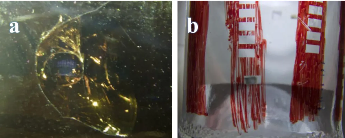
the photographs of the two sides of this stained glass sample. It can be observed that the internal side of the glass sample is in a better state of conservation than the external side. Viewed from the internal side, feather-like patterns painted with grisaille can be recognized (Fig. 2.4.1(a)). Some small craters filled with whitish deposits could also be observed on this side. On the external side of the glass sample, it can be observed that many areas of edge portion were covered by a thick layer of yellowish crust. We consider that the crust could be attributed to residual deposits of putty and/or cementing materials used to fix the glass piece into lead cames. A detailed discussion of this point will be provided in chapter 5. Microbial colonization was not observed on this historic glass sample.
7Fig. 2.4.1 Photographs of the stained glass sample: (a) internal side; (b) external side
It has been mentioned earlier that the grisaille is usually applied on the interior side of the stained glass windows. However, for this sample, the grisaille is located on its external surface. This may be due to a previous erroneous restoration, or the grisaille was originally fired on the external surface (Becherini et al., 2008). As can be seen in Fig. 2.4.1(b), several strongly adhered crusts were formed in painted areas on the external surface. Removing crusts from the glass sample in this case is correspondingly more challenging.
2.4.2.- Samples of commercial modern glass
The work was initiated with some commercial modern pieces of transparent and colored glasses. They are a beer bottle and a cosmetic recipient. These samples have been used to learn the use of the high power lasers and to define the range of conditions of the laser that can be used minimizing the possibilities of creating some defects on glass. In addition, some particular experiments have been performed on pieces of window glass and microscope slides.
28
CHAPTER 3: IDENTIFICATION OF ABLATION THRESHOLD
IN COMMERCIAL MODERN GLASS
Initially we performed some experiments in industrial glasses in order to explore the different kind of defects that the laser treatment can generate in the surface of the glass and to determine which laser parameters can be used without damaging the glass. We choose two different bottles of brown and transparent glass, with some commercial advertisements sticky on their surface.
It is important to have in mind that glass is a fragile material and the high thermal stresses that can be generated due to the localized high temperatures generated during the laser treatment can induce crack generation.
3.1.- Effect of using the UV laser to process brown industrial glass
First experiments were conducted to perform laser treatments directly on the glass. The laser has scanned areas of 12.5 mm2 (5mm × 2.5mm) using a continuous
bidirectional mode with a laser scan speed of 50 mm/s, a frequency of 300 kHz and a distance between scanning lines of 10 microns. We have chosen this frequency because with lower frequencies the pulse energy is higher and the ablation processes, which are relevant in the laser cleaning process, are more important. A set of experiments with increasing values of laser power has been performed. The spot fluence has varied from 1.47 J/cm2 up to 3.52 J/cm2, the particular experimental
details are recorded in Table 3.1 and the aspect of the irradiated area is presented in Fig. 3.1.1.
The effects of these laser treatments were examined using confocal microscopy. Particular attention has been given to the border of the treated area in order to have better comparisons between radiated and original surface and because in these regions the effect of the laser is stronger as we have explained in section 2.2.1.
With some of the conditions at the higher fluence values, Fig. 3.1.2 shows that several cracks are generated in the glass, always in the perpendicular direction in comparisons to the scanning one. In particular, this is observed when the fluence reaches values higher than 2.79 J/cm2. Fig. 3.1.3 shows an example of the
measurement of the topography in these regions.
9
Fig. 3.1.1 Photograph of the bottle after laser treatment
1
Table 3.1 Parameters used in the laser treatments performed on irradiation regions
Irradiation regions 1 2 3 4 5 6
Pumping power (A) 5.00 5.30 5.60 6.00 6.30 6.60
Laser power (W) 1.00 1.12 1.25 1.40 1.57 1.70
Spot fluence (J/cm2) 1.47 1.64 1.84 2.06 2.31 2.50
Spot irradiance (MW/cm2) 4895.19 5482.61 6118.99 6853.27 7685.45 8321.83
Irradiation regions 7 8 9 10 11
Pumping power (A) 7.00 7.15 7.25 7.50 8.00
Laser power (W) 1.90 1.975 2.025 2.15 2.40
Spot fluence (J/cm2) 2.79 2.90 2.97 3.16 3.52
30 10Fig. 3.1.2 Images obtained with confocal microscope of irradiation regions
7(a), 8(b), 10(c) and 11(d) on the borders between treated and untreated areas
11Fig. 3.1.3 Image obtained with confocal microscope of irradiation region 10
showing the defects that are generated in the glass topography
a
b
c
d
Region 7 Region 8
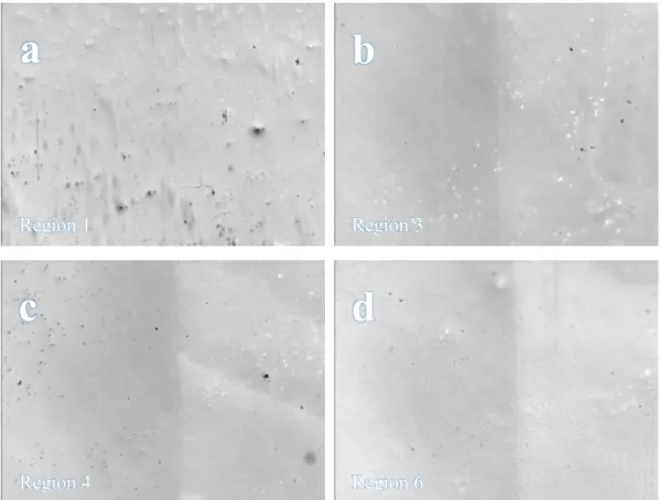
12Fig. 3.1.4 Images obtained with confocal microscope of irradiation regions
1(a), 3(b), 4(c) and 6(d) on the borders between treated and untreated areas
13Fig. 3.1.5 Image obtained with confocal microscope of irradiation region 6
showing no change in the topography
Fig. 3.1.4 shows some examples of the regions treated with lower fluence values. With these laser conditions, only small relative changes in morphology were observed. No straps or cracks were generated on the surface of the treated areas. As it can be observed in Fig. 3.1.5, the confocal scans also do not show measurable
a
b
c
d
Region 1 Region 3