UNIVERSIDADE DA BEIRA INTERIOR
Engenharia
Manufacturing Techniques of a Hybrid Airship
Prototype
Sara Emília Cruz Claro
Dissertação para obtenção do Grau de Mestre em
Engenharia Aeronáutica
(Ciclo de estudos integrado)
Orientador: Prof. Doutor Jorge Miguel Reis Silva, PhD Co-orientador: Prof. Doutor Pedro Vieira Gamboa, PhD
AVISO
A presente dissertação foi realizada no âmbito de um projeto de investigação
desenvolvido em colaboração entre o Instituto Superior Técnico e a Universidade
da Beira Interior e designado genericamente por URBLOG - Dirigível para
Logística Urbana. Este projeto produziu novos conceitos aplicáveis a dirigíveis,
os quais foram submetidos a processo de proteção de invenção através de um
pedido de registo de patente. A equipa de inventores é constituída pelos
seguintes elementos:
Rosário Macário, Instituto Superior Técnico;
Vasco Reis, Instituto Superior Técnico;
Jorge Silva, Universidade da Beira Interior;
Pedro Gamboa, Universidade da Beira Interior;
João Neves, Universidade da Beira Interior.
As partes da presente dissertação relevantes para efeitos do processo de
proteção de invenção estão devidamente assinaladas através de chamadas de
pé de página. As demais partes são da autoria do candidato, as quais foram
discutidas e trabalhadas com os orientadores e o grupo de investigadores e
inventores supracitados. Assim, o candidato não poderá posteriormente
reclamar individualmente a autoria de qualquer das partes.
Covilhã e UBI, 1 de Outubro de 2015
_______________________________
(Sara Emília Cruz Claro)
Dedicator
I want to dedicate this work to my family who always supported me.
To my parents, for all the love, patience and strength that gave me during these five years. To my brother who never stopped believing in me, and has always been my support and my mentor.
To my sister and my lovely nephews, for all the love and support.
I also want to dedicate this work to my boyfriend, Tiago, who, undoubtedly, without his effort, it would not be possible to finish this stage of my life in five years.
“Every man is the architect of his own fortune.”
Acknowledgements
I want to give my sincere thanks to all who believed in me and supported me over these five years.
To my family, for all the love, support and patience and to my soulmate Tiago, that was always my support, my best friend, and for helping me overcome all the difficult moments of this journey. I love you all!
To the friends and great colleagues that I made along this journey. Without forgetting my housemates, that made my stay in Covilhã even better and never boring.
To my advisor, Professor Jorge Miguel Reis Silva, whom I am grateful for all the knowledge, patience, and time spent during the preparation of this dissertation. Thank you for the friendship and I’ll never forget what we did for me. I also want to thank to my co-adviser Professor Pedro Vieira Gamboa, for the knowledge and all the advises that improve my dissertation.
To João Neves, who was essential to this Project. My gratitude for the effort, time spent, knowledge passed to me and all the advices that will be useful for all my life.
To Tiago Santos, my partner in this journey, for the help and patience. I also want to express my gratitude to Laura Martins and Inês Cruz for the availability whenever needed.
To Professor Rosário Macário and Professor Vasco Reis from Instituto Superior Técnico, for their time and participation in this work.
To Santos Esteves- Representações Lda, especially to Sr. Nuno Esteves, for the amiability and for offering essential material to complete this work and to Citeve (Centro Tecnológico das Industrias Têxtil e do Vestuário de Portugal), for information that made my ideas clear and help given, especially to Engº Helder Rosendo.
Resumo
Encontramo-nos numa era em que assistimos ao aumento da procura de transportes alternativos. Este interesse advém do aumento do preço dos combustíveis fósseis, devido à sua escassez, da poluição ambiental além do congestionamento das infraestruturas. Uma alternativa será o uso de dirigíveis híbridos, que poderá vir a colmatar as falhas, acima mencionadas, dos transportes mais usados atualmente. Por isso, o estudo desta tecnologia tem sido cada vez mais aprofundado em todo o mundo. Desta forma, o objetivo desta tese visa, principalmente, o planeamento de construção da estrutura e gasbags de um protótipo de um dirigível híbrido com um novo conceito de estabilidade e controlo.
Antes da construção deste protótipo à escala do projeto real, houve a necessidade de fazer testes de conceito em protótipos mais pequenos. Assim, um blimp em PVC foi adaptado para estes testes, perfazendo três protótipos. Os dois primeiros (1 e 1.5) tiveram o objetivo de testar a estabilidade e controlo de todas as superfícies e o último (2.5) de testar o desempenho de um dirigível quad-rotor com controlo de passo fixo.
Após estes testes estarem concluídos, passou-se à construção de uma secção da estrutura do protótipo final, chamado de Protótipo 3 com cerca de 9 metros. Requisitos iniciais de projeto deliberaram que a elaboração desta componente teria que ser feita à mão, tornando assim obrigatório um estudo da melhor forma de o conceber, otimizando assim o tempo e qualidade de construção da estrutura completa. Da mesma forma, houve a necessidade de estudar-se materiais e o melhor método de construção de gasbags para a retenção de hélio.
Palavras-chave
Dirigíveis, manufatura de dirigíveis rígidos, manufatura de estruturas de dirigíveis, manufatura de gasbags.
Abstract
Nowadays we witness a growing demand for alternative means of transportation. This interest stems from the rising price of fossil fuels, due to its scarcity, environmental pollution beyond the congestion of infrastructures.
An alternative is the use of hybrid airships, which may fill the gaps mentioned above of the transport commonly used today. Therefore, the study of this technology has been increasingly extensive throughout the world. Thus, the objective of this dissertation aims, essentially, the manufacture planning of a Prototype’s structure and gasbags of a hybrid airship with a new concept of stability and control.
Before the construction of this Prototype, there was a need to do concept tests in smaller prototypes. Thus, a PVC blimp was adapted for these tests, and for these adaptation was given the name prototypes too. The first two of them (1 and 1.5) had the objective of testing the stability and control of all surfaces and the last (2.5) to test the performance of a quad-rotor airship with fixed pitch control.
After these tests had been completed, the next step was the construction of a section of the structure of the final prototype, called Prototype 3, with approximately 9 meters. Initial project requirements, decided that the development of this component would have to be done by hand, thus was essential a study of the best way to conceive, in order to save time and increase the build quality of the complete structure. Likewise, it was necessary to study the best gasbags materials and construction, so that they have the best performance in helium retention.
Keywords
Table of contents
Dedicator ... v
Acknowledgements ... vii
Resumo ... ix
Abstract... xi
Table of contents ... xiii
List of figures ... xv
List of tables ... xix
List of acronyms ... xxi
1. Introduction ... 1
1.1 Motivation ... 1
1.2 Object and objectives ... 1
1.3 Dissertation structure ... 2
2. State of art ... 3
2.1 Introduction ... 3
2.2 Airships manufacturing ... 3
2.2.1 Airships – definition and classification ... 3
2.2.2 Rigid airship manufacturing ... 4
2.2.3 Rigid and Semi-Rigid airships manufacturers nowadays ... 6
2.3 Jigs design in aeronautical industries ... 7
2.4 Rigid airship structure manufacturing ... 8
2.4.1 Truss structure manufacturing ... 10
2.5 Gasbags manufacturing ... 11
2.5.1 Materials ... 12
2.5.2 Helium permeability – Gas permeation theory ... 15
2.5.3 Envelope manufacturing methods ... 17
2.6 Conclusion ... 18
3. Adaptation of a blimp for stability and control tests ... 19
3.1 Introduction ... 19
3.2 Prototype 1 – adaptation for stability and control tests ... 19
3.2.1 Carbon fiber lamination ... 20
3.2.2 Support jig manufacturing ... 21
3.2.3 Manufacture of the landing gear ... 22
3.3 Prototype 1.5 and 2.5 adaptation for stability and control tests ... 24
3.3.1 Prototype 1.5 - wings manufacture ... 24
3.3.2 Prototype 1.5 - wings fittings ... 27
3.3.3 Prototype 2.5 - rotors fittings ... 30
3.4 Conclusion ... 30
4. Prototype 3 – Manufacture methods ... 31
4.1 Introduction ... 31
4.2 Gasbags manufacturing ... 31
4.2.1 Gasbags materials ... 31
4.2.2 Manufacturing tests ... 33
4.2.3 Permeability tests of LDPE/PET-MET/LDPE ... 38
4.2.4 Gasbag manufacturing method using heat sealable fabric... 40
4.3 Structure manufacture ... 46
4.3.1 Nomenclature ... 46
4.3.2 Construction jig ... 51
4.3.3 Manufacturing test 1- 1m truss ... 52
4.3.4 Manufacturing test 2 – frames and girders ... 55
4.3.5 Structure section assembly – fitting system ... 61
4.4 Assembling Jig ... 62
4.4.1 Conceptual design of an assembling jig ... 62
4.4.2 Assembling jig modifications ... 64
4.5 Conclusion ... 64
5. Conclusion ... 67
5.1 Dissertation synthesis ... 67
5.2 Final considerations ... 67
5.3 Prospects for future work ... 68
References ... 69
ANNEX 1 - Permeability Tests Results ... 73
ANNEX 2 - Scientific Paper Accepted for Publication at the 18th ATRS Conference ... 75
List of figures
Fig. 1 - Airship types [1] ... 4
Fig. 2 - Hindenburg profile, showing major elements and numbering system for gas cells and frames [6] ... 5
Fig. 3 - Hindenburg under construction [6] ... 5
Fig. 4 - Skycat Prototype [8] ... 6
Fig. 5 - (a) Cessna Citation X fuselage assembly jig [14]; (b) Airbus A300-600ST transport jig [15] ... 7
Fig. 6 - Construction Jig for wings ribs [16] ... 8
Fig. 7 - Circular frame assembly Jig of a rigid airship structure [18] ... 9
Fig. 8 - (a) LZ-1 internal frame jig; (b) Erecting the first ring of USS Akron’s frame, March 1930 [18] ... 9
Fig. 9 - Auxiliary device for assembling airships [20] ... 10
Fig. 10 - Beam-like truss structures of the new Zeppelin NT [21] ... 10
Fig. 11 - Britain's R 101 airship under construction at the Royal Airship Works, Cardington ... 11
Fig. 12 - Section trough typical laminate material [1] ... 13
Fig. 13 - Handmade blimp [23] ... 17
Fig. 14 - (a) Single lap joint; (b) Single strap joint [28] ... 18
Fig. 15 - Radio Frequency heat welding [29] ... 18
Fig. 16 - PVB Blimp measurements ... 20
Fig. 17 - Extruded polystyrene wings ... 21
Fig. 18 - Blimp’s support Jig ... 22
Fig. 19 - Extruded polystyrene landing gear ... 22
Fig. 20 - Electric motor’s support cone manufacture ... 23
Fig. 21 - Electric motor’s support cone addaptation ... 24
Fig. 22 - Wing manufacture (1). ... 25
Fig. 23 - Wing manufacture (2). ... 25
Fig. 24 - Wing manufacture (3). ... 25
Fig. 25 - Wing manufacture (4). ... 26
Fig. 26 - Wing manufacture (5). ... 26
Fig. 27 - Wing manufacture (6). ... 26
Fig. 28 - Balsa wings manufactured (7) ... 26
Fig. 29 - Control surfaces support ... 27
Fig. 30 - PLA support structure ... 27
Fig. 32 - Attachement of wood support... 29
Fig. 33 - Collage of fitting profiles among Servo and wing ... 29
Fig. 34 - Adaptated Blimp realizing stability and control tests ... 29
Fig. 35 - Rotor’s fittings ... 30
Fig. 36 - Template cut ... 33
Fig. 37 - Adhesive application ... 34
Fig. 38 - Finished Balloon ... 34
Fig. 39 - Second Bonding ... 35
Fig. 40 - First bonding... 35
Fig. 41 - Different bondings allong the balloon ... 35
Fig. 42 - Reinforced Bonding ... 35
Fig. 43 - Fissure after filling balloon with air ... 36
Fig. 44 - Manufacture test with the application of tesa® Flooring Tape Extra Strong Hold into two different fabrics ... 36
Fig. 45 - Manufacture test with LDPE/PET-MET/LDPE ... 37
Fig. 46 - Gasbag nomenclature ... 41
Fig. 47 - Welding Jig ... 41
Fig. 48 – Gasbag manufacturing procedure (1) ... 42
Fig. 49 - Gasbag manufacturing procedure (2) ... 42
Fig. 50 - Gasbag manufacturing procedure (3) ... 43
Fig. 51 - Gasbag manufacturing procedure (4) ... 43
Fig. 52 - Gasbag manufacturing procedure (5) ... 43
Fig. 53 - Gasbag manufacturing procedure (6) ... 44
Fig. 54 - Gasbag manufacturing procedure (7) ... 44
Fig. 55 - Gasbag manufacturing procedure (8) ... 44
Fig. 56 - Gasbag manufacturing procedure (9) ... 45
Fig. 57 - Gasbag manufactured ... 46
Fig. 58 - Prototype 3’s structure ... 47
Fig. 59 - Frame quadrants ... 47
Fig. 60 - Example of frame’s quadrant numenclature ... 48
Fig. 61 - Some components nomenclature ... 49
Fig. 62 - Example of nomenclature of girders between frames ... 50
Fig. 63– Example of the nomenclature that was given to girders pieces ... 50
Fig. 64 - Prototype 3 section structure’s construction jig ... 52
Fig. 65 - Composite truss with 1m ... 53
Fig. 67 - Defective bonding ... 54
Fig. 68 - Finishing touches (final sanding) ... 54
Fig. 69 –Structure’s manufacture. (a) Procedure 1; (b) Procedure 2 ... 57
Fig. 70 - Girders manufacture ... 60
Fig. 71 - Structure's fitting system ... 61
Fig. 72 - Assembly of structure’s section ... 61
Fig. 73 - Complete Assembly Jig ... 62
Fig. 74 - Exploded view of half Assembly Jig ... 63
Fig. 75 - (a) Frames and girders attachment system; (b) Fitting system of support and longitudinal pieces ... 63
List of tables
Table 1 - Comparison of the most common synthetic fibers used in Envelopes [1] ... 13
Table 2 - Typical Properties of film materials for possible use in laminated materials for a gasbag. (Main properties) [1] ... 14
Table 3 - Typical Properties of film materials for possible use in laminated materials for a gasbag. (Secondary properties) [1] ... 14
Table 4 - Properties comparison of fabrics [1] ... 15
Table 5 – Total mass and mass lifted by helium during the 1st test ... 38
Table 6 – Volume of helium inside the balloon at t0 and t72 ... 39
Table 7 - Percentage of helium lost during the 2nd test ... 40
Table 8 – Materials and tools for Gasbag manufacture ... 41
Table 9 – Working time of gasbag manufacture ... 45
Table 10 - Element’s Symbols of the Frame ... 47
Table 11 - Material and tools used for jig’s manufacture ... 51
Table 12 – Working time of 1m truss manufacture... 55
Table 13 - Materials and tools necessary for frames’ manufacture. ... 56
Table 14 - Material used in each type of piece of frames ... 56
Table 15 – Working time of a quadrant of a frame ... 58
Table 16 – Materials used in each type of piece of the girders ... 59
List of acronyms
EVA Ethylene-vinyl acetate
ATG Advanced Technologies Group
CNC Computer Controlled Cutting
LDPE Low-density polyethylene
LTA Lighter than air
MET Metalized
PET Polyethylene terephthalate
PLA Polylactic acid
PTFE Polytetrafluoroethylene
PVC Polyvinyl chloride
PVDC Polyvinylidene chloride
PVF Polyvinyl fluoride
1. Introduction
1.1 Motivation
Airships had their golden age in the 1930s, but have fallen into disuse after the accident of the German model Hindenburg. Currently, the ideal of 'green' transports, which exhibit low fuel or electricity consumption and produce less pollutants, is in vogue. Hence it is so important further research on alternative transport that, moreover also, allow the decongestion of cities due to traffic. Thus returned to be necessary a deepen knowledge in the field of airships in order to make them a new option.
However, this means of transport has some disadvantages, among them, the difficulties of control and stability, making this study the largest area of interest. Allying today's latest technology of control, stability, propulsion, structures and materials to the 'airship' concept, it is possible to fill all the disadvantages of the past making this the future of transport using clean energy, serving mainly for surveillance, advertising, recreational and freight transportation.
As research about this a technology almost stagnated, it is anticipated further development work and adaptation to new technologies, which makes inherent and essential the search of new construction methods due to the use of new materials and configurations.
This dissertation is part of the project ‘UrbLog’, made in partnership between the Universidade da Beira Interior and the Instituto Superior Técnico, referring to a new concept of hybrid airship, more stable and controllable.
To build a scale prototype of this project, is necessary to test all parts of the conceptual design to validate concepts, and find solutions to problems that may arise in terms of construction method. As in any other new technology project, all initial ideas must be validated before, to be possible an appropriate constructive planning, for the development of the final design could be optimized in terms of time, money and quality.
1.2 Object and objectives
The object of the current dissertation is the study of manufacturing techniques to apply on the construction of a prototype that will test a new concept of hybrid airship, and the adaptation of a blimp for small conceptual tests.
The first objective is to adapt a blimp for tests on stability and control. If these tests are inconclusive, it is demonstrated that it is not feasible to continue the project. Hence, this practical work of adaptation is essential to the project.
The second and most important objective is the development of a manufacturing plan of the final Prototype 3’s structure and gasbags. Within this, we can divide into several sub-objectives. The first is getting the best manufacturing method for making the structure of the prototype 3. The second is to investigate materials to make helium gasbags and determine the best manufacturing techniques. The third is to design an assembling jig for Prototype 3 final assembly.
1.3 Dissertation structure
This dissertation is divided into five chapters.
The first chapter is the study introduction, which is divided into three sub-chapters, the motivation, the object and objective, and the structure of the dissertation, respectively. The second chapter corresponds to the state of art and contains the general study of the construction of airships up to today. Includes general definition of airships, the current manufacturers, methods used to construct the structure and gasbags, materials used for the construction of gasbags and a brief study about the helium permeability and its gas permeation theory.
In the third chapter is possible to observe the description of all blimp adaptation work for stability and control tests.
The fourth chapter refers to the case study, where was studied the best manufacture methods for the structure and gasbags of Prototype 3. It also includes a brief study of materials, its permeability and the conceptual design of an assembly jig for the final assembly of Prototype 3.
The fifth (and last) chapter contemplates the dissertation synthesis, the final considerations and the prospects for future work in this matter.
2. State of art
2.1 Introduction
This chapter aims to give a general view of the state of the art of airships manufacture. Will start with a brief introduction to airships, then deepening the construction methods applied to them. As this work mainly aims at the construction of the structure and gasbags, these are the two most studied aspects.
The construction of these two important components of the airship requires a general planning. That is, for the construction of the final prototype, one structured planning is needed and inside that, the design of special tools. Thus, this chapter also contains the study of airship and other aircraft jigs.
2.2 Airships manufacturing
2.2.1 Airships – definition and classification
An airship, also known as dirigible, is a type of aerostat, or lighter-than-air (LTA) aircraft. Basically is a powered balloon with a means of propulsion and its shape is modified in order to be an effective vehicle. This way, its format must be studied in order to reduce aerodynamic drag and enhance the controllability.[1] So the common airship formats have some similarities to conventional aircraft.
There are four categories of airships (Fig. 1): Rigid, Semi-Rigid, Non-Rigid and Hot Air Airships. The rigid airships have an internal frame. This structure holds up the shape of the airship. A Semi-Rigid airship usually contains a rigid lower keel construction and a pressurized envelope above that. The rigid keel can be attached directly to the envelope or hung underneath it. As for Non-Rigids, this kind of airships is also known as Blimp and basically a large balloon full of gas. Its shape is maintained by the internal overpressure. The last type are the Hot Air Aiships, or Thermal Airships, although they are in another category, are part of Non-Rigid because is the same concept. The difference is the gas, in this case, this type of airship use hot air [1, 2]. Currently, have been a greater investment in the construction of vehicles that derive most of their lift from Aerostatic principles, on the other hand their useful cargo capacity rely on Aerodynamic lift. These new concepts is known generically as Hybrid Airships [3].
Fig. 1 - Airship types [1]
2.2.2 Rigid airship manufacturing
Considering that this project aims to build a rigid airship, only this type of construction will be studied.
Usually, rigid airship contained a rigid hull frame, generally built up of longitudinal girders which are connected at intervals by polygonal ties, constructed of a lightweight but strong material providing a rigid structure within which were the lifting gas cells; machinery; fuel and living/working space. A separate cover went over the outside of the framework to provide streamlining and weatherproofing [4].
Zeppelin is an example where this type of construction is applied. This is a type of rigid airship whose name was a tribute to Ferdinand von Zeppelin, a German Count, who pioneered the development of rigid airships in the twentieth century.
On Zeppelin airships, was usual that every second tie was braced athwart ships by a radial wire truss, through the hub of which a steel hawser runs from stem to stern. Both the hawser and the radial truss wires were fitted with turnbuckles whereby the whole framework may be tightened up when required. The radial, or tie, trusses form the compartments in which from individual gas-cells are housed; the cells were drum-shaped and were fitted with an inflation appendix and a relief-valve [5].
An example is the Hindenburg Zeppelin (Fig. 2, a large German commercial passenger-carrying. This ship was built with triangular duralumin girders forming 15 main rings, connecting 36 longitudinal girders, with a triangular keel at the bottom of the hull, an axial corridor at the center of the ship, and a cruciform tail for strength [6].
The construction of this kind of airships is time-consuming, strict and expensive. Considering as the initial construction requirement the size, this undergoes the need for a large space, a hangar.
The hangars that were constructed for this purpose are huge infrastructures, the biggest ever created to construct airships [7]. Due to the complexity of manufacture, the hangar should be provided with Industrial tools of construction (jigs) and good working conditions. The construction of this airship forced the use of welding techniques for light alloys for the fabrication of lattice-girders. After this, all parts are attached on a support structure, as shown in Fig. 3. This support structure allows that all components are placed in the correct place, while the construction is not complete. After the building, this framework of wood or metal is removed. This is the basis of building for all rigid airships.
Fig. 3 - Hindenburg under construction [6]
After the disaster of LZ 129 Hindenburg, that caught fire and was destroyed, the manufacturing of these 'air monsters' fell into disuse, decreasing the evolution of this kind of construction until a few years ago, when it started to believe in this technology and to focus on their research. However, nowadays there are only a few companies manufacturing rigid airships, and so there are few production hangars.
Fig. 2 - Hindenburg profile, showing major elements and numbering system for gas cells and frames [6]
2.2.3 Rigid and Semi-Rigid airships manufacturers nowadays
As mentioned above, airships are divided into 4 categories: rigid, semi-rigid, non-rigid and hot air airship. Concerning the manufacture, the requirements to build semi-rigid and rigid structures are very similar, because both have an internal structure.
After the disaster with Hindenburg, was not so common the manufacture of airships, but there are still some companies that invest in this mean of transportation. Due to the complexity of building, and requirement of large hangars, only a few remaining countries have these conditions. Nowadays there are very few construction hangars for rigid and semi-rigid airships, and the best known are in Germany, England and the United States of America.
In Germany, there is the Zeppelin Luftschiftechnik GmbH descendant of the ancient industry of Count von Zeppelin, was established in September 1993 to design, build and operate a semi-rigid airship with the new technologies available, leading to the "NT Programme".
There is also the CargoLifter AG, founded in September 1996 in order to develop the project of a multifunctional semi-rigid airship, the CargoLifter CL-160, to carry heavy loads and surplus volumes. For this purpose was built in the area of a former Soviet base, a huge hangar, with 360m long, 210 m wide and 107 m high.
Further north, England holds the 'Advanced Technologies Group (ATG)' established in 1996 to continue with the activities of the former Airship Industries Company, responsible for British airships designated Skyship 500/600 series. It has two projects at this moment, the SkyCat (Fig. 4), which is a hybrid airship, and StratSat, a stratospheric airship unmanned to serve as telecommunications platform.
In the United States there is the World Aeros Corporation, which was established in Ukraine in 1988 and transferred its activities to California in 1993. It produces a variety of vehicles "lighter than air", manned and unmanned for military and civilian applications. In 1999 it was created the Aeros Airship Company in order to develop large airships: the Aeros D-1, with a capacity of 14 tons, and the Aeros D-4, to 124 tons of cargo [9].
(a) (b)
In Portugal has never been common the development, construction and operation of airships, but a few years ago Nortávia, an aerial transportation company, started the project of a solar airship, Gaya. Until now the final design has not yet been conceived, the prototype was the only one manufactured in Portugal [10].
2.3 Jigs design in aeronautical industries
Any aircraft project have a complex structure, and for each one is essential its manufacturing planning. If this planning is done well, optimizes its production mainly in terms of time, quality and price.
A rigid airship is conceived as a complete structure, but for manufacturing purposes must be divided into sections, or main components that are split into sub-assemblies of decreasing size, resolved into individual detail parts. In any industry a significant factor, in conjunction with the quality of the product is its productivity. This isn’t an exception in aeronautical industry and because of that a good manufacture plan is required. Inside this plan is necessary a good design of floor assembly jigs, to build every single part [11, 12].
In summary, a JIG is a fixture used to locate, clamp and support all the elements of a piece, putting them together on the correct place, in a rigid unit during a manufacturing operation. That it is known as a template that ensures that each part is accurately made to the shape of the template and that considerably depends of the skill of the operator [12, 13]. So, this involves a generator tool frame, locator and clamp placement to guarantee that the assembly components is made properly respecting the required tolerances. For each different project is necessary a tool designer that analyze the best tool design to warrant that the assembly process is performed correctly without causing accessibility or ergonomic problems and need to considerate the accuracy and rigidity too, followed by ease of use, and economy in construction. If this tool is well designed will ensure the interchangeability and accuracy of parts manufactured, minimize the possibility of human error, permit the use of medium-skilled labor, reduce the manufacturing time and allow the production of repeat orders without retooling [11, 12].
Fig. 5 - (a) Cessna Citation X fuselage assembly jig [14]; (b) Airbus A300-600ST transport jig [15]
There are a lot of examples of jigs used in aircraft manufacturing, some of them are presented in the previous figures, were is shown a Cessna Citation X fuselage assembly jig (Fig. 5a) and an Airbus A300-600ST transport jig (Fig. 5b).
Also for the construction of model aircraft are developed jigs, for example, for the construction of wings ribs is usually design a jig table that contains the template of the piece (Fig. 6).
In conclusion, one jig is a manufacture supporting tool, designed according to the requirements of the type of construction, the shape and purpose as transportation, assembly, manufacture, placement and other needs.
2.4 Rigid airship structure manufacturing
As mentioned above, a rigid airship shape can be maintained independent of envelope pressure because the envelope is usually supported by a lightweight but strong framework. Usually, the framework of the external support structures, are composed of transverse girders forming approximately circular frames, and longitudinal girders successively through the length, as shown in Fig. 7. Transverse girders, are connected by longitudinal girders, and are cross-braced with pre-tensioned metal wires to confer adequate rigidity upon the whole assembly for increased structural strength. This structure was normally made by aluminum alloys and all the girders made of trusses [4, 17].
All parts of the beams are pre-assembled. The Fig. 7 shows the assembly of a circular frame where the ‘rings are built flat on the floor and hoisted into place, the wheel-like markings on the floor are jigs for smaller circular frames’ [18].
Fig. 6 - Construction Jig for wings ribs [16]
Fig. 7 - Circular frame assembly Jig of a rigid airship structure [18]
After the beams, circular and longitudinal frames be ready, they were assembled. In the case of Zeppelin LZ 1 (Fig. 8a) the structure was mounted over an aluminum frame supported by wooden structure [19]. In the USS Akron (ZRS-4) the rings of circular frames were erected using strong cables (Fig. 8b).
Through time, new assembly methods have been developed. As an example, Durr Ludwig patented an Auxiliary device for assembling airships (Fig. 9). This invention is a jig made of wood, light metal or high grade steel shapes that can readily and rapidly assemble the airship body [20].
Fig. 8 - (a) LZ-1 internal frame jig; (b) Erecting the first ring of USS Akron’s frame, March 1930 [18]
2.4.1 Truss structure manufacturing
The structure of rigid airships should be as light as possible and extremely strong. Initially they were metallic, for example using lightweight aluminum alloys, but new materials have been developed over time and the beams of metallic trusses could be replaced by, for example, composites. At this moment 'lightweight carbon fiber rods and truss structures with high stiffness, high strength and sufficient durability are more and more important for advanced transportation technologies' [21]. If metal alloys are used, the trussed beams can be made directly with the desired shape by metal casting and molding. The join of different parts is made by welding or bolting. When the trusses are made by composite material, in particular carbon, the part can also be made directly with the desired shape. In this case the part is laminated and consists of a polymeric matrix and a reinforcing material, carbon. The joints between beams can be made by application of this polymer matrix, or even screwed.
Fig. 10 - Beam-like truss structures of the new Zeppelin NT [21]
The new Zeppelin NT has an internal structure which combines aluminum and carbon fiber. The Fig. 10 shows a truss beam from structure of the Zeppelin NT that comprise aluminum and carbon fiber trusses [21].
2.5 Gasbags manufacturing
The UrbLog Project refers to a hybrid airship, and its shape is given by a rigid structure. Therefore, unlike non-rigid airship, the helium internal pressure, an inert gas chosen for sustain, don't ensure the shape of the aerostat. It is normal that, this type of airships have internal compartments for retaining the gas. These compartments are called gasbag and are usually made of fabric ideally not permeable.
Although, the purpose of the gasbag is not the same as the envelopes of non-rigid airships, the behavior of both should be very similar, and therefore, have similar fabrication requirements. In the case of gasbags, as they are not in contact with external conditions, it does not require as high resistance to environmental degradation, but is an important point to consider for the part lifetime.
Thus, the required properties of the material for manufacturing Gasbags are [1, 23]:
High strength to weight ratio to minimize the weight of the gasbag;
Resistance to environmental degradation trough temperature and humidity;
Good tear and abrasion resistance to give damage tolerance;
Low permeability to minimize helium loss. This loss results in loss of operational capability and increased operational costs;
Joining techniques that produce strong and reliable joints, not subject to creep rupture;
Minimum price;
Maximum material life vs. ease of field repair.
Fig. 11 - Britain's R 101 airship under construction at the Royal Airship Works,
2.5.1 Materials
In the golden days of airships, the development in the field of Textile Engineering was poor, but over the years there has been great progress in the research of new materials. With the development of synthetic materials, the textiles used in airship manufacture had undergone many changes.
In the beginning of rigid airship, it is known that gas cells of earlier German Zeppelins were made of goldbeater’s skin (the outer membrane of cattle intestines). Latter, Hindenburg innovates using a new material the construction of the gas cells. This material ‘was made by brushing layers of gelatine onto a sheet of cotton, this gelatine film was sandwiched between two layers of cotton to create the fabric for the cells’ [6].
About more materials used in the construction of gasbags, there is almost none bibliography, so the investigation of the state of the art was continued based on the development of textiles for the envelopes.
For the first envelopes were used natural fibers, including cotton and rubber. This envelopes were made by plied rubber coated fabric, two or three plies of cotton fabric bonded together with natural rubber. The cotton plies were based relative to each other in order, to claim shear strength, stiffness and tear resistance. The natural rubber sealed the fabric. Firstly, material was joined by a mix of sewn and bonded joints to maintain good contact in the joint while the bonding, agent rubber cement, cured. To reduce permeability, the envelope was sealed with paraffin on the inner surface. However, this material had poor properties by the modern standards [1].
With the technological evolution, new materials were found, and the first use of synthetic products in envelope materials was the replacement of natural rubber by neoprene (chloroprene) rubbers. This one has much improved weatherability and a lower permeability than natural rubber. This properties allowed less maintenance of the envelopes, because the life of material was extended. But, unfortunately, the material still had a very limited strength. Latter, new base fabrics made from synthetics fibers was found, with better strength for low weight, such as Polyamides (nylon), and Polyesters [1].
Nowadays, new envelope materials have been developed, which is the case of laminated materials. This modern materials allows that in the same film there are several fabric layers with different properties. Together they have the required properties for the envelope [1]. Generally, envelope laminate film is made of gas retention, woven load bearing and environmental/ weathering protection layers that are bonded together with an adhesive layer, like is shown in the Fig. 12.
Fig. 12 - Section trough typical laminate material [1]
For woven load bearing layer, is required that the material need to be flexible, so this component needs to be a woven fabric. So, there is a large selection of synthetics fibers with relevant properties. The Table 1 makes a comparison of the most common synthetic fibers used.
Table 1 - Comparison of the most common synthetic fibers used in Envelopes [1]
Material Fibre Specific Gravity Fibre Tensile Strenght GPa (lb/in2) Fibre Modulus GPa (lb/in2)
Polyester Low Excellent Yes
Polyamide Low Poor Yes (with
adhesives)
Aramid-high
modulus Low Fair No
Aramid – Low
modulus Very Low Fair Yes
In the case of gasbags that will be used in the prototype 3, studied in this work, the most important properties are its permeability and adhesion to other materials. The material should have a low permeability, in order to lose less gas as possible, and, as the construction of this part will be done manually, it should be used a material which is easily sealable. Thus, the choice of material to use in gas retention film is very important.
In Table 2 are listed some materials commonly used in the manufacture of envelopes, that could also be applied to our gasbags.
Table 2 - Typical Properties of film materials for possible use in laminated materials for a gasbag. (Main properties) [1]
Material Gas
Permeability
Adhesion to
Fabrics/Film Heat Sealable
Polyurethane Low Excellent Yes
Polyvinyl
Fluoryde Low Poor
Yes (with adhesives)
Polyester Low Fair No
Nylon Very Low Fair Yes
PVDC Copolymer
(Saran) Very Low Fair Yes
PTFE Fair Poor Yes (some
grades only)
Low Density
Polyethylene Fair Poor Yes
PVC Fair Low Excellent Yes
Table 3 - Typical Properties of film materials for possible use in laminated materials for a gasbag. (Secondary properties) [1]
Material Tensile
Strenth
Flex Fatigue
Resistance Weatherability
Polyurethane 4,000-10,000 Good Good
Polyvinyl
Fluoryde 8,000-16,000 Excellent Excellent
Polyester 25,000-45,000 Fair Fair
Nylon 10,000-17,000 Excellent Poor
PVDC Copolymer
(Saran) 7.000-16.000 Fair Poor
PTFE 3,000 Good Excellent
Low Density
Polyethylene 1,000-2,300 Excellent
Good (if pigmented)
PVC 1,000-3,000 Good Good
The properties were divided into two tables. The first (Table 2) shows the main properties required for the gas retention film to use in this project, and the second (Table 3) shows important priorities, but not so relevant for the design of this prototype.
Normally, the preferred material is polyester, being the polyester film (Mylar –Du Pont) the most common component. This film has low permeability and is relatively strong and stiff. Usually the gas retention film already consider the weathering component, but when not, is
usual the use of a protective film in the weathering protection layer. A comparison of fabrics used previously is shown in Table 4.
Table 4 - Properties comparison of fabrics [1]
Neoprene Polyurethane Polyvinylfluoride
P rop e rti e s SG 50% greater than
polyurethane or PVF Very low helium permeability Very low helium permeability Modest weatherability
gives 3 years life with frequent maintenance
i.e. painting.
Very good handling properties and crease
resistance Resists fungal growth
Must be joined with adhesive
Good weatherability gives 5 year life with
modest maintenance Excellent weatherability gives 15 to 20 year life with
no maintenance Very easy to handle
and join (by adhesive or heat bonding)
Polyvinylfluoride (PVF) film, has proven to be greater resistant than most synthetic materials, and his long life with almost zero maintenance made that one the most common material used for weathering protection of envelopes [1].
2.5.2 Helium permeability – Gas permeation theory
It was previously established that the lifting gas chosen for the ‘UrbLog’ prototype would be helium. This gas have very small molecules that are notoriously difficult to contain, to avoid leakage [24]. Because of that, the gasbag material needs to have a low helium permeability, because the loss of helium translates into lifting force deficit during the airship operation, and also increase the cost of operation too. So it is very important to know the permeability of the material that will be used.
By the gas permeation theory is possible to obtain the volume of gas passing through an area per unit time across a sample [25].
The transport of gases through a solid membrane is a solution-diffusion mechanism where the permeants dissolve in the membrane down a concentration gradient. This consists of three processes [25, 26]:
Absorption of the permeant into the polymer;
Diffusion through the polymer;
Desorption or evaporation of the permeating species from the polymer surface and removal.
The driving force behind the transport process which involves the sorption, diffusion and permeation is the gradient concentration between the two sides of the membrane. This process is designated by Fick’s laws of diffusion described by [26]:
𝐽 = −𝐷 (𝜕𝐶 𝜕𝑥), 𝜕𝐶 𝜕𝑡 = 𝐷 ( 𝜕2𝐶 𝜕𝑥2) (1) Where,
-𝐽 is the flux in the direction of the flow [𝑚𝑜𝑙 𝑚⁄ 2. 𝑠], -𝐶 is the concentration of permeant [𝑚𝑜𝑙 𝑚⁄ 3], -𝑡 is the time [s],
-𝐷 is the diffusion coefficient [𝑚2⁄ ], 𝑠
-𝑥 is the position within the membrane down the concentration gradient [m].
After some permeation time, the steady-state is reached and that implies that the concentration is remaining constant at all points within the membrane. Under these conditions and by introducing boundary conditions for a planar sheet, it is possible to describe the flux by:
𝐽 = −𝐷𝐶0− 𝐶1
𝑙 (2)
Where,
-𝐶0 and 𝐶1 are the permeant concentration upstream and downstream side of the membrane; -𝑙 is the membrane thickness [cm].
In a system where a gas diffuses through a membrane, the concentration may be replaced by the gas partial pressure. So J is described by:
𝐽 = −𝑃
𝑝
0− 𝑝
1𝑙
(3)Where,
-𝑃 is the permeability coefficient [𝑚𝑜𝑙 𝑚. 𝑠. 𝑃𝑎⁄ ],
-𝑝0 and 𝑝1 are the gas partial pressure on either side of the membrane [Pa].
If the diffusion coefficient is constant over the pressure range, the permeability coefficient may be rearranged to:
Where,
-𝑆 is the Solubility coefficient[m3 (STP)⁄𝑚3. Pa].
To calculate the permeability coefficient is necessary to measure the flux and pressure gradients in the both side of the film, in order to determinate the diffusion coefficient [26].
2.5.3 Envelope manufacturing methods
The processes used in airship envelope fabrication must be properly defined to guarantee a high quality airship envelope. The endurance of the airship envelope depends not only of the material used but also on the design, its seams and accessories too, as well as the procedures for fabrication and final assembly [23].
For airship with large infrastructure, there is no literature available about the construction methods of envelopes or gasbags. However, for small hand-made blimps, it was possible to determine some methods. In all of them, the production starts by defining the pattern and, consequently, the number of sections in which the piece will be split to achieve the desired shape after their union, as we can see in the following figure Fig. 13 [23].
As for the sections joints, it is needed to take into account the type of material that was used for manufacturing the envelope/gasbag.
For small homemade blimps it is preferred that the material is heat sealable, as this is the most common form of union. However, sometimes it is not possible to apply this method to some of the used materials, such as envelopes made of polyester film. In this case the joints must be made using contact adhesives. Silicon sealant and cyanoacrylate can work, but silicone is heavy and takes a long time to cure, while cyanoacrylate is not flexible, so the joint cracks easily. One choice for the contact adhesive is UHU Power Stick. In the case of use of this glue to make the joints, it must follow the following procedures [27]:
1. Clean both joint surfaces;
2. Spread UHU Power Stick across the joint area of each surface; 3. Wait a minute for it to dry;
4. Press the two sections together and make the joint; Fig. 13 - Handmade blimp [23]
5. Apply some heat in the joints, with the help of an iron to unify the glue along all contact section.
The joins must be made as pictured in Fig. 14 (a) and (b).
Fig. 14 - (a) Single lap joint; (b)Single strap joint [28]
If welding can be used in this materials, start by setting the welding area in each section. After this being delineated, join the two sections and apply heat with an iron so that the edge is welded. This procedure must be followed for all the sections until achieve the desired shape. For the envelope shown in Fig. 13, it was welded by radio frequency heat welding as can be seen in Fig. 15.
2.6 Conclusion
The construction quality of an airship is crucial to its good performance. The type of construction, methods and tools vary by size, type of structure, materials and kind of operation. So it is important a good constructive planning and design tools for optimize the production in terms of time, cost and errors.
As such, and because there is no rule in terms of construction, this state of the art contemplated comprehensively a summary of the manufacture of rigid airships, building structures, gasbags and design tools.
Since the manufacture of rigid airships is not as common as up to 1920, the available literature on the construction methods of the components is very short, such as information on the manufacture of gasbags and their materials. With this it is necessary determine, in a practical way, the best methods to apply in the manufacture of the Prototype 3 of 'Urblog' Project.
(a) (b)
Fig. 15 - Radio Frequency heat welding [29]
3. Adaptation of a blimp for stability and
control tests
3.1 Introduction
This dissertation is part of the project 'UrbLog'. This project aims the development and construction of a hybrid airship with an innovative stability control system, and is part of a partnership between Universidade da Beira Interior and Instituto Superior Técnico.
Airships are known for the difficulty to control and stabilize them so, in this project, this will be the main area of study. Due to the inexperience of the working group on airships, there was the need to make flight tests to better understand the concepts of control and stability and for that was used a small PVC blimp. It was important to confirm this project feasibility, validating, this way, the construction of prototype in real scale, the Prototype 3.
Since the monetary and logistic conditions for the construction of Prototype 3 were not yet available, it was necessary to optimize the time and continue the research into smaller prototypes that were cheaper and required less resources. They also allowed the optimization of the research because each of these prototypes has been adapted to the specific area that we want to investigate. The PVC blimp was then adjusted for a set of tests, and in each one was made a different adaptation. So, we call to each of this adaptations Prototype 1, Prototype 1.5 and Prototype 2.5. Thus, this chapter describes all the upgrading works that the blimp suffered.
Spite of not being the main objective of this work, it was an important part that defined the ongoing experimental work for the planning of the construction of Prototype 3. Therefore, and for a better understanding of the work developed, the blimp’s adaptation is described only in this chapter.
It is important to refer that the stability and control tests were part of another dissertation, and therefore placement of parts, materials and purposes of the tests are justified in that document [30]. Thus, this chapter only describes the construction work carried out in accordance with the requirements.
3.2 Prototype 1 – adaptation for stability and control tests
Prototype 1 consisted of the adaptation for stability and control tests of a previously manufactured PVC Blimp. It was therefore necessary to find support solutions for wings and propeller, finding the best manufacturing method for wings and fittings.
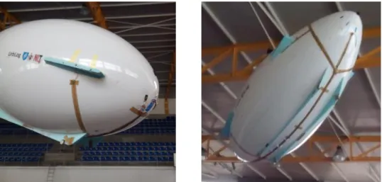
First of all, the balloon was filled with air, and then was bonded a measuring tape around (Fig. 16). This tape, glued lengthwise, aimed to help to do symmetrical marking to attach all the pieces.
3.2.1 Carbon fiber lamination
Throughout the project, there was the need to use several pieces of carbon fiber. Therefore, this small sub-chapter explains in a brief way the lamination process used.
It was necessary to use a mould, in all parts made of carbon fiber. The procedure carried out for laminating were as follows [31]:
1. Apply Release Agent or brown tape to the mould to prevent the carbon fibre part from sticking to it.
2. Cut the Carbon Fiber. The piece of fabric should be cut according to the size of the mould, and must be divided the best way possible to cover it up. Cutting must be made with a suitable scissor.
3. Weigh the carbon fiber that will be used.
4. Mix Epoxy Resin and Hardener. The amount of the mixture must have the same weight of carbon fiber and the proportion of the resin is 2 parts of epoxy resin with 1 part of epoxy hardener.
5. Apply a bit of resin mixture in the mould uniformly.
6. Lay Carbon Fabric into the mould in order to cover it completely. Check that there is no wrinkles.
7. Apply resin mixture and spread uniformly using a flexible and smooth spatula to don’t affect the fabric.
8. Repeat the process as many times as necessary according to the number of carbon fiber layers.
9. Absorb, carefully, the excess of resin mixture with smooth paper. 10. Leave to cure for 24 hours.
11. Remove the piece carefully of the mould and cut the excess.
3.2.2 Wings Manufacture
For carrying out the test it was necessary to build six wings. Four horizontal and two vertical. The material chosen for its construction was extruded polystyrene because it is relatively lightweight, easy to give the desired shape and cheap. The best way to cut accurately throw the extruded polystyrene is hot wire, thereby, after the wings are drawn, they were cut in a hot wire CNC machine. After cut and inspected the wings for defects, they were carefully covered with white duct tape, reaching the appearance shown in the following Fig. 17a and Fig. 17b.
(a) (b)
After coating, was made an opening, in the four horizontal wings, to introduce a metal pipe. This circular pipe, had function of a hinger support, supporting the wings but allowing rotational movement, for changing the angle of attack (Fig. 17b).
As can be seen in Fig. 17a, were made some small parts of carbon fiber to allow the connection of the wing to the servo through a metal rod.
These pieces were cut from a laminated carbon fiber board having two layers of fabric. For the purpose of positioning the horizontal wings in the correct place supporting components have been made. These components made of extruded polystyrene were cut and sanded by hand, until reaches the blimp’s shape.
3.2.2 Support jig manufacturing
Fit components in a balloon filled with air is quite complex. Applying a small force, changes its shape, as well as not remaining stable. All work needed to be carried out by at least two persons for the blimp not to move. So there was the need to build a support jig where the blimp could be supported, but so it does not interfere with the adjustments work.
The solution was to make a support Jig (Fig. 18), that could be modular so it can be transported. Not being an essential part, it was decided that the material to use was extruded polystyrene because it was cheap and easy to cut.
Were then cutted two boards of extruded polystyrene with the profile of the bottom of blimp. These should be hot wire cutted on the CNC machine but its size do not allow cutting of such large parts. Then it had to be handmade, using a sharp blade knife. The assembly and disassembly is quick and easy, as well as fulfilling the intended purpose.
3.2.3 Manufacture of the landing gear
The Blimp’s material, PVC, was fragile, and because of that, it was needed to safeguard it in landings. For this it was conceived a landing gear.
Once more, this component should be easy to install, functional and lightweight. So, the lower shape of the filled balloon was draw on extruded polystyrene, and then, that was cut with a sharp blade. It was made two supports, with the format shown in the Fig. 19. Then, in each of these, were glued two plastic wheels.
Fig. 18 - Blimp’s support Jig
This landing gear was glued to the blimp with double-sided self-adhesive (tesa® Flooring Tape
Extra Strong Hold). Finally, two carbon wires were bonded between the extruded polystyrene
parts, which served as tensors, to maintain the landing gear with the desired shape and position.
3.2.4 Tail cone manufacture
The position of the propeller motor was chosen in the conceptual design and it was concluded that this would be on the back of the blimp. However, the filling and exhaust gas valve was at the tail, so, it was necessary to build a motor support structure that could be removable. Necessarily this structure had to be as light as possible.
The solution went through the elaboration of a cone in carbon fiber that fit perfectly in the blimp's tail without affecting the envelope made of PVC. For this purpose, was made a mould of extruded polystyrene, through gluing overlapped layers of this material. This overlap was then cut and sanded manually until it reaches the desired shape. After finishing the mould, it went through a process of lamination with carbon fiber.
The mould was covered with tape so that there were no fiber adherence to this after it has dried. Then carbon wire were placed vertically, dividing the piece into eight reinforcing it structurally. It was also applied a carbon fiber tape with approximately 3 cm wide in the bottom of the mould. Then, the entire mold was covered with fiber, on top of the cone was placed a circumference of pre-made rigid carbon and the entire mold was again covered with carbon fiber. The lamination process of this part was made according to the procedure of subsection 3.2.1.
In order to avoid direct contact between the carbon tail cone and PVC blimp, the contact areas were reinforced with EVA foam. This foam was bonded by contact adhesive. Finally, were made some openings on the top of this part to be possible the motor’s housing.
Fig. 20 - Electric motor’s support cone manufacture
To secure the cone to tail the Blimp carbon strips were glued around. These strips are cut from a laminated plate previously. The manufacturing process of this card is described in Chapter 3.2.1.
It was glued adhesive Velcro tape at the tips of carbon strips, as at the bonding areas on the blimp's tail. The bonding via Velcro allowed to put and to withdraw the cone easily whenever necessary.
1
3.3 Prototype 1.5 and 2.5 adaptation for stability and control
tests
Since the wings of Prototype 1 were heavier than desired, other set of lighter wings were made for new flight tests. Due to the weight savings, the landing gear was also removed.
3.3.1 Prototype 1.5 - wings manufacture
In order to reduce wings weight, it was decided to build the wings in balsa wood and covering film, as it is commonly used in aeromodelling.
Initially, was printed the template of the wings format and cutted, in a laser machine, the balsa ribs with 2 mm of thickness. The cutting of the ribs must take into account the reinforcement part of the lead, and trailing edge of the wing and spars. These parts were also cut beforehand. For spars and leading edge, has been used a square balsa profile with 10mm thickness, and in trailing edge the reinforcing part has a balsa board of 2 mm thick and 15 mm
1 Parte da dissertação relevante para efeitos do processo de proteção de invenção referido no
Aviso no início deste documento.
wide. The glue used was Permabond® ET515 Semi Flexible 15min Epoxy Adhesive 50ml Twin
Tube.
Then it was been carried out the following manufacturing process:
1 – Glue the template under an extruded polystyrene board.
2 – Place the spar and fit the ribs in the right places according to the template. Glue the pieces with cyanoacrylate.
3 – Turn the wing around and glue the other spar and the reinforcement part of the leading edge and trailing edge.
Fig. 23 - Wing manufacture (2). Fig. 22 - Wing manufacture (1).
4 – Cover the leading edge with 1 mm balsa board.
5 – Glue 2mm thick balsa boards in order to cover the two spars increasing the structural strength of the wing.
6 – Glue, on the tops of all the ribs towards the leading edge, balsa strips 1mm thick and 7mm wide. These increase the bonding area of the covering film.
8 – Finally, after the drying process, apply the covering film across the wing [32]. This film adheres to the balsa through the application of heat with an covering film iron [33].
Fig. 26 - Wing manufacture (5). Fig. 25 - Wing manufacture (4).
Fig. 27 - Wing manufacture (6).
Fig. 28 - Balsa wings manufactured (7).
3.3.2 Prototype 1.5 - wings fittings
The support structure of the wings in the prototype 1 was heavier than possible, and so it was necessary to develop a new engagement structure for the new wings.
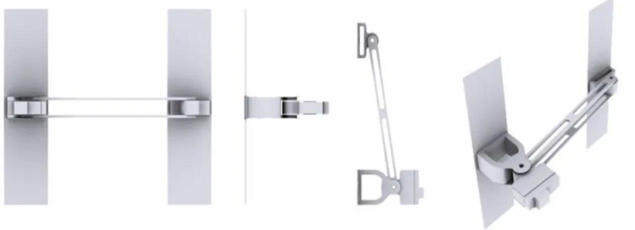
This structure also aimed to change the wing sweep. Thus, the designed wing’s support structure is as shown in Fig. 29.
Fig. 29 - Control surfaces support
This set was designed to allow the fitting of the wings of the prototype 1.5 as the fitting of the rotors on prototype 2.5.
Its operation is very simple. It has two separate components that allow increasing the contact area with the blimp, making this a more stable mechanism with less risk of fall or change of form. One of these components has a compartment where the servo, or the rotor support tube, was placed. This component have free horizontal movement, allowing the modification of the wing swept.
A construction option was the printing of parts through a 3D printer using PLA (Fig. 30). It was a relatively easy and quick construction process without the need for manual labor.
After 13 hours, the support parts have been printed. The material used was PLA and the print result shown to be slightly defective, in addition to the set of pieces was heavier than expected, about 44.3g in total (Fig. 30).
Due to imperfections of the components, it was necessary to sand them internally to be able to fit the Servo and the rotor metal pipe.
Despite this support piece is mechanically robust, did not fulfilled the most important requirement, low weight, thus resorted to the more traditional construction method using wood.
To make the new support parts, were used plywood plates. The shape of these layers have been cut by a laser machine. Then all the pieces were glued with cyanoacrylate. It can be seen, in the final assembly of the support part (Fig. 31).
The cut process of the parts, and gluing, took less time than its printing by the previous manufacturing method, however, the drying time, about 24h, increased manufacturing time. On the other hand the weight of the support piece was about 29.7g, much lower than the previous value. Thus, we chose to use the wooden support pieces because, despite its method of manufacture is more complex and time consuming compared to 3D printing, the weight difference was substantial.
To attach this support structure to Blimp, it was decided to glue the contact components to flexible carbon strips. These strips were cut from a laminated carbon fiber plate as it was previously explained in section 3.2.1. Then, the carbon strips were glued to EVA to not put carbon in direct contact with the Blimp (Fig. 32).
Fig. 33 - Collage of fitting profiles among Servo and wing
The servo was placed within a docking component of the support piece, and a wooden plywood profile was applied. These profiles were then glued to the wings (Fig. 33).
Finally, the servo fitting component was screwed to the support part with plastic screws. To reinforce the supports tensioners were placed between the wing and the blimp. These were carbon wire and were bonded to the balloon with adhesive velcro tapes. On the wing, the tensioners were fixed into the external rotation axis. Fig. 34 shows the blimp during test flight with wings and fittings mentioned above.
Fig. 32 - Attachement of wood support
Fig. 35 - Rotor’s fittings
3.3.3 Prototype 2.5 - rotors fittings
To support the rotors, the same method has been used for fitting the wings foregoing. The only difference was that at structural level, in the supporting parts, the servo has been replaced by a square tube used for fixing the rotors.
Each rotor was bolted to a square metal pipe. The other top was glued with hot glue into its slot which was coupled to the support piece (Fig. 35). For a greater structural strength, were placed clamps around the set of embedded parts.
3.4 Conclusion
As previously mentioned, the work of this chapter was not the main objective of the current dissertation however, without the adaptation of the blimp, would not be possible to determine the validity of the researched construction techniques to apply in Prototype 3. So it was important to document all the work made.
The applied solutions were viable, and so it was possible to make the flight tests required for the validation of concepts of another dissertation [30]. Therefore this purpose was concluded successfully.
Finally, all the work invested in the adaptation of the blimp turned out to be very time consuming, jeopardizing the start of the tasks of the next chapter that was the main goal of this thesis.
4. Prototype 3 – Manufacture methods
4.1 Introduction
After the consolidation of knowledge and concept validation through tests performed with the prototypes 1, 1.5, 2 and 2.5, we proceeded with the planning of the construction of a real scale prototype of 'Urblog'. To this has given the name Prototype 3.
Within this planning, it was necessary to test the best construction methods for structure and gasbags in addition to the assembly jigs design.
It was previously established that the material used for the structure would be carbon composite, but as for the material for the gasbags construction, had not yet been made any study. Therefore, this chapter includes the best method for the construction of the structure and a brief study and tests to find the best material for gasbags.
For the development of all components it was also necessary to develop appropriate construction and assembly tools.
Therefore, the aim of the study discussed in this chapter was the development of building tests of some components so, that time consume and building quality, of Prototype 3, were optimized.
4.2 Gasbags manufacturing
Its known that in the latest rigid airships, the materials used for the construction of gasbags are manufactured using the latest technology. It must be lightweight, durable and especially the least permeable as possible, so there is no loss of sustainer gas. The operation of airships becomes more expensive, due to gas losses, and this makes the investigation of materials to this component of extreme importance on project [34]. Thus, because the research for new materials is so expensive and valuable, there is no literature available about these materials and construction techniques.
However, the gasbags designed in this dissertation concerns a prototype (Prototype 3) for conception testing, and not to the final project, the requirements are not as demanding in terms of construction.
4.2.1 Gasbags materials
As previously mentioned, the choice of materials to use in the gasbag is very important for a proper operation of the prototype, without sustainer gas leakage. For Prototype 3, the chosen sustainer gas was helium, and there are few fabrics that have a low permeability.
![Fig. 1 - Airship types [1]](https://thumb-eu.123doks.com/thumbv2/123dok_br/18692625.915298/26.892.279.568.118.434/fig-airship-types.webp)
![Fig. 2 - Hindenburg profile, showing major elements and numbering system for gas cells and frames [6]](https://thumb-eu.123doks.com/thumbv2/123dok_br/18692625.915298/27.892.324.611.668.887/hindenburg-profile-showing-major-elements-numbering-cells-frames.webp)
![Fig. 10 - Beam-like truss structures of the new Zeppelin NT [21]](https://thumb-eu.123doks.com/thumbv2/123dok_br/18692625.915298/32.892.118.715.108.402/fig-beam-like-truss-structures-new-zeppelin-nt.webp)

![Table 1 - Comparison of the most common synthetic fibers used in Envelopes [1]](https://thumb-eu.123doks.com/thumbv2/123dok_br/18692625.915298/35.892.228.705.515.733/table-comparison-common-synthetic-fibers-used-envelopes.webp)
![Table 4 - Properties comparison of fabrics [1]](https://thumb-eu.123doks.com/thumbv2/123dok_br/18692625.915298/37.892.163.774.199.529/table-properties-comparison-of-fabrics.webp)