Heat transfer in heterogeneous lightweight wall systems
with cement panel
Dissertation
Master in civil engineering – Building construction
Yurii Skubko
Heat transfer in heterogeneous lightweight wall systems
with cement panel
Dissertation
Master in civil engineering – Building construction
Yurii Skubko
Dissertation developed under the supervision of professor Florindo José Mendes Gaspar, adjunct professor at Departament of Civil engineering of the Polytechnic Institute of Leiria and co-supervision of professor Nikolay Sytnichenko, professor at the Donbas National Academy of Civil Engineering and Architecture .
Resumo
Em lugar de materiais de construção padrão, soluções alternativas começaram a aparecer gradualmente. Uma dessas soluções é um sistema de parede leve desenvolvido pela Knauf usando o painel de cimento AQUAPANEL® OUTDOOR.
O sistema sob investigação é caracterizado pela sua heterogeneidade, que é determinada pela sua composição.
A possibilidade de usar sistemas leves na envolvente de edifícios deve ser confirmada por cálculos de parâmetros de projeto termofísicos.
As características da parede exterior utilizando o painel AQUAPANEL® OUTDOOR, nomeadamente a presença de uma estrutura de metal ou de madeira, elementos maciçaos requerem atenção especial e confirmação dos cálculos da resistência térmica.
O estudo da operação conjunta dos elementos de sistemas leves para verificação dos requisitos de proteção térmica na operação de edificações determinará o grau de influência destes sistemas nos parâmetros sanitários e higiénicos de proteção térmica.
A investigação das características de proteção térmica de sistemas leves em instalações novas ou reconstruídas, levando em conta a influência de defeitos na envolvente do edifício, permite quantificar a capacidade de compensação de reduzir os custos de energia de cada sistema;
A análise da eficiência do uso de sistemas leves permitirá avaliar o efeito econômico da utilização de um sistema específico do ponto de vista da redução de custos operacionais.
Objetivo:
1. Considerar os dados reais, trabalhos e literatura sobre este assunto; 2.Construção de paredes de teste que representem dois sistemas leves;
3. Realizar pesquisas para determinar a heterogeneidade térmica dos sistemas; 4. Realizar uma análise sistemas com dois equipamentos de imagem térmica;
5. Executar uma simulação computacional do processo de transferência de calor e comparar os resultados com os reais;
6. Realizar um estudo de viabilidade comparando as soluções tradicionais.
Palavras-chave: Paredes leves, AQUAPANEL® OUTDOOR, características térmicas, transferência de calor, coeficiente de transferência de calor, condutividade térmica, fluxo de calor, dispositivos de imagem térmica.
Abstract
Instead of standard building materials, alternatives are gradually being used more and more in construction. One of these alternatives is a lightweight wall systems using the cement panel AQUAPANEL® OUTDOOR.
The investigated system is characterized by heterogeneity, which is determined by its design features.
The possibility of using light systems as enclosing structures of buildings should be confirmed by calculations of thermo-physical parameters of the construction.
As features of constructive solutions for the external walls with the use of cement boards, namely the presence of a metal or wooden frame, massive wall elements require special attention and supporting calculations for thermal resistance.
Research on the joint work of elements of light systems, in compliance with the requirements of thermal protection during the operation of buildings, will allow determining the degree of influence of these systems on the sanitary and hygienic parameters of thermal protection.
Investigation of thermal protection characteristics of complete systems on new or reconstructed objects, taking into account the influence of defects of building envelope structures, allows quantitatively determining the compensatory capacity of reducing the energy consumption of each system.
An analysis of the efficiency of the use of light systems will allow assessing the economic effect of using one or another system from the point of view of reducing operating costs.
Objective:
1. Consider the actual data, works and literature on this theme; 2. Build two different testing walls which represent light systems;
3. Conduct research to determine the thermal heterogeneity of the systems; 4. Conduct an analysis of the walls with two thermal imaging devices;
5. Run a computer simulation of the heat transfer process and compare the results with the real results;
6. Conduct a feasibility study comparing with the traditional solutions.
Keywords: Lightweight wall systems, AQUAPANEL® OUTDOOR, thermal characteristics, heat transfer, coefficient of heat transfer, thermal conductivity, heat flux, thermal imaging devices
List of figures
Figure 2.1: External wall with direct fastening of plates to steel frame ... ….14
Figure 2.2: External wall with direct fastening of plates to wood frame ... ….15
Figure 2.3: The edge of the AQUAPANEL® OUTDOOR boards and its appearance ... ….21
Figure 2.4: Mineral wool «Knauf Insulation» Termo Roll 040 ... …. Figure 2.5: Municipal building - the Supreme Administrative Court of Bulgaria, Sofia .. ….29
Figure 2.6: Shopping Center Boom, Athens, Greece ... ….29
Figure 2.7: Residential Complex, Denmark ... ….30
Figure 2.8: Villa Akarp, Malmo, Sweden ... ….31
Figure 3.1: Heat flow that passes through a lightweight wall system ... ….35
Figure 3.2: Geometric models of the investigated constructions ... ….40
Figure 3.3: The structure of the static thermal analysis of the heterogeneous designs of Ansys Workbeanch ... ….41
Figure 3.4: The distribution of temperature fields inside the surface of the investigated structure (family 1) ... ….42
Figure 3.5: The distribution of temperature fields outside the surface of the investigated structure (family 1) ... ….42
Figure 3.6: The distribution of temperature fields in the depth of the investigated structure (family 1). ... ….42
Figure.3.7: The distribution of temperature fields in the depths of the investigated structure (family 2) ... ….43
Figure 3.8: The distribution of temperature fields in the thickness of the investigated structure in a stepped section ... ….43
Figure 3.9: The distribution of temperature fields in the thickness of the investigated structure in a section (family 2) ... ….43
Figure 3.10: The distribution of temperature fields on the inner surface of the angular exploration structure (family 1) ... ….46
Figure 3.11: The distribution of temperature fields on the outer surface of the angular exploration structure (family 1) ... ….46
Figure 3.12: The distribution of temperature fields on the internal section of the angular investigated structure (family 1)………...47
Figure 3.13: The distribution of temperature fields in the external section of the angular investigated structure (family 1) ... .…47
Figure. 3.14: The distribution of temperature fields on the inner surface of the angular exploration structure (family 2) ... .…48 Figure 3.15: The distribution of temperature fields in the external section of the angular investigated structure (family 2) ... ….48 Figure 3.16: Distribution of temperature fields on the internal section of the angular investigated structure (family 2) ... ….49 Figure 4.1: Scheme of experimental installation for the study of heat-engineering properties of the design of the family 1 ... ….51 Figure. 4.2: Sequence of installation of investigated structures... ….52 Figure. 4.3: Thermal imaging equipment used for measurements ... ….53 Figure. 4.4: The images of the internal surface of the two structures are made by Flir E8 and Flir C2 devices at 10.00 o'clock on January 19, 2018. ... ….54 Figure. 4.5: Three-dimensional surface of the response of the inner surface of a single-row construction ... ….55 Figure. 4.6: Three-dimensional surface of the response of the inner surface of a duble-row construction ... ….56 Figure. 4.7: Location of the studied points on the surface of structures ... ….57 Figure. 4.8: Graph of temperature distribution along the surface of the investigated structure, depending on the temperature of the outside air (family 1. 17.01.2018) ... ….58 Figure. 4.9: Graph of temperature distribution along the surface of the investigated structure, depending on the temperature of the outside air (family 1. 19.01.2018) ... ….59 Figure. 4.10: Graph of temperature distribution along the surface of the investigated structure, depending on the temperature of the outside air (family 2. 17.01.2018) ... ….60 Figure. 4.11: Graph of temperature distribution along the surface of the investigated structure, depending on the temperature of the outside air (family 2. 19.01.2018) ... ….61 Figure. 5.1: The scheme of heat transfer of the brick external wall with the external system of the heat insolation ... ….65 Figure. 5.2: The scheme of heat transfer of a layered wall of foam blocks………...…...67 Figure. 5.3: Analysis of the areas ... ….70
Figure.5.4: Value for labor input, cost of materials and total cost of erection depending on the type of exterior walls used………71
List of tables
23Table 2.8 : Characteristics of sealing Linoterm-P tape ... 24
Table 2.9 : Characteristics of fastening products for fastening of plates AQUAPANEL® OUTDOOR to a steel frame ... 25
Table 2.10 : Characteristics of fastening products for fastening of drywall sheets to steel frame ... 26
Table 2.11 : Characteristics of reinforcing tape ... 27
Table 2.12 : Characteristics of fiberglass for reinforcement of basic plaster layer ... 27
Table 2.13 : Characteristics of a spatula mix on cement basis "Akapanel Gray"………28
Table 3.1 : Input parameters for process simulation. ... 41
Table 4.1 : Data on temperature distribution on the inner surface of the family structure 1. Date of the experiment: January 17, 2018 ... 57
Table 4.2 : Data on temperature distribution on the inner surface of the family structure 1. Date of the experiment: January 19, 2018 ... 58
Table 4.3 : Data on temperature distribution on the inner surface of the family structure 2. Date of the experiment: January 17, 2018 ... 59
Table 4.4 : Data on temperature distribution on the inner surface of the family structure 2. Date of the experiment: January 17, 2018 ... 60
Table 5.1 : Heat engineering indicators of building materials of the outer wall 1 ... 65
Table 5.2 : Heat engineering indicators of building materials of the outer wall 2 ... 67
Table of Contents
Resumo ... ..3
Abstract ... ..4
List of figures ... ..5
List of tables………...7
CHAPTER 1 DISSIPATED LIGHTWEIGHT WALL SYSTEM: SPHERE OF USE, TARGET AND OBJECTIVES OF RESEARCH………....10
1.1 Introduction ... 10
1.2 The purpose and objectives of the master's dissertation, subject, object of study, research methods and scientific novelty ... 11
CHAPTER 2 THE GENERAL ANALYSIS AND CHARACTERISTICS OF THE STRUCTURES. SETTING GOALS AND CURRENT STATUS QUESTION…………13
2.1 Overview of constructions ... 13
2.2 Analysis of existing expirience ... 15
2.3 Classification of lightweight wall systems ... 17
2.4 Materials and component parts ... 18
2.4.1 Elements of frame ... 19
2.4.2 Reinforced cement and mineral boards AQUAPANEL® OUTDOOR ... 19
2.4.3 Heat and sound insulating materials ... 21
2.4.4 Material wind waterproof materials ... 22
2.4.5 Steam insulation materials ... 24
2.4.6 Seals ... 24
2.4.7 Connecting products ... 25
2.4.8 Tapes ... 27
2.4.9 Plaster mixes and mixes, primers, adhesives ... 28
2.5. Expirience of use lightweight wall systems ... 28
2.8 Conclusion of the second section ... 34
CHAPTER 3 EVALUATION SHIELDING PROPERTIES COMPLETE SYSTEM BY CAE ANSYSWORKBENCH………...35
3.1 The essence assessment thermo heterogeneous systems ... 35
3.2 Using the finite element method for static thermal analysis ... 36
3.3 Procedure and analysis of lightweight wall systems using CAE Ansys Workbench ... 40
3.4 Thermotechnical analysis of angular designs lightweight wall systems CAE Ansys Workbench ... 45
3.5 Conclusions on the third section ... 50
CHAPTER 4 CONDUCTING THE EXPERIMENT FOR INVESTIGATION THE THERMAL CHARACTERISTICS OF THE SYSTEMS ... 51
4.1 Construction of experimental walls to test results ... 51
4.2 Conducting thermal investigation ... 52
4.3 Comparison of values obtained by Flir E8 and Flir C2 ... 54
4.5 Experimental results ... 55
4.5.1 The distribution of temperature on the inner surface ... 55
4.5.2 Temperature dependence of internal surface design of the outside temperature of air ... 56
4.6 Conclusion of the fourth chapter ... 62
CHAPTER 5 TECHNICAL-ECONOMIC COMPARISON OF VARIANTS FOR EXTERNAL WALL CONSTRUCTIONS ... 63
5.1 Thermotechnical calculation walling type 1 (brick wall) ... 64
5.2 Thermotechnical calculation walling type 2 (layerd masonry) ... 66
5.3 Comparison of area buildings ... 69
5.4 Economic efficiency ... 70
5.5 Ecological resistance ... 72
5.6 Conclusion of the fives chapter ... 73
GENERAL CONCLUSIONS……….………74
CHAPTER 1
DISSIPATED LIGHTWEIGHT WALL SYSTEM: SPHERE OF USE, TARGET AND OBJECTIVES OF RESEARCH
1.1 Introduction
The last decades of the XXI century were characterized by significant achievements in the construction industry. High rates of modern buildings construction required the development of new, energy-efficient high-quality, economic enclosing structures with improved characteristics.
In place of heavy traditional building materials (brick, foam block, reinforced concrete walls, etc.), light-weight frame-and-casing structures gradually began to arrive. There are many similar constructions. The Knauf company developed such designs solutions named lightweight wall systems.
The lightweight wall system is a new generation construction system designed to create durable building structures and has advantages not typical for traditional building materials. Being a weather-resistant construction system, the lightweight wall system is absolutely moisture resistant and is made of inorganic materials, so it is not susceptible to mold and fungus formation, does not soften and does not swell when exposed to water.
The weight of the structure is 75% lower than the walls constructed with traditional materials, while the system provides greater design freedom and superior performance in all applications. In new construction or reconstruction, the complete lightweight wall systems offers unmatched benefits in terms of economy and eco-stability.
Currently, with so many serious advantages, lightweight wall system is still not fully understood. Its thermal characteristics are not so well studied, especially in the territory of Ukraine.
An urgent task for future research is to determine thermal resistance, linear heat transfer coefficient of structures and heat flow that passes through them .
1.2 The purpose and objectives of the master's dissertation, subject and object of study, research methods and scientific novelty
The purpose of this research is to study thermal characteristics of lightweight wall systems, determination of thermal resistance, a comparison of two thermal imaging devices, technical and economic comparison of different traditional solutions and lightweight wall systems.
To achieve this goal the following tasks were performed:
- Research the existing data, literature and works on this experiment; - Build two different testing walls of lightweight wall systems;
- Conduct research to determine the heterogeneity of the systems of heating; - Conduct analysis of the walls with two thermal imaging devices;
- Run a computer simulation of the heat transfer process and compare the results with the real results
- Determine the conformity of lightweight wall systems to the building codes for thermal characteristics;
- Conduct a feasibility study comparing with the traditional solutions. The subject of study was the heterogeneous lightweight wall systems.
The object of study was two lightweight wall systems of diferent composition. In this dissertation the following research methods were used:
- Literature search and review; - Analysis;
- Design of external walls; - Tests;
Research present tests made on real built construction, which was placed in a real weather conditions of Kramatorsk.
The scientific novelty of dissertation is the possibility of using lightweight wall systems in Ukraine.
This dissertation gives data about the heat transfer properties of the walls studied in this investigation.
The practical value of the dissertation is that values of the thermal resistance were determined experimentally in the real walls, based on which a conclusion on the possibility of using these structures in Ukraine and given the recommendations on the possibility of using thermal imaging equipment for specific thermal studies
CHAPTER 2
THE GENERAL ANALYSIS AND CHARACTERISTICS OF THE STRUCTURES. SETTING GOALS AND CURRENT STATUS QUESTION
2.1 Overview of constructions
The lightweight wall systems, developed using the AQUAPANEL® OUTDOOR cement slab, are systems of pre-fabricated frame structures of external walls.
Distribution of drywall technology became possible recently due to various new building technologies. Until recently these materials were not designed for outdoor use. The company Knauf has developed a cement slab AQUAPANEL® OUTDOOR – rectangular sheet material consisting of a core based on fine-grained lightweight concrete, all the planes of which, apart from the end edges, are reinforced with fiberglass.
Reliability and durability of AQUAPANEL® OUTDOOR, both in terms of strength and in terms of reliability of thermal protection, depends on the elements of design quality and performance quality. The overall technical documentation for this technology, represented now in Ukraine, is only advisory in nature.
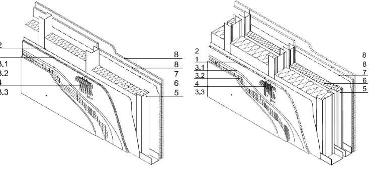
Complete lightweight wall systems for use in buildings for different purposes, are design-element assembly and consist of a bearing steel or wooden frame with external AQUAPANEL® OUTDOOR cladding boards and internal cladding sheets of drywall. There is an air - filled cavity between the cladding of heat - and sound-proof material. On the outside, under the sheathing, a wind- and water-proof layer is attached, and on the inside – a vapor barrier. The design of these walls is presented in Figures 2.1 and 2.2.
In terms of price, the system is competitive comparing with traditional building materials , combined with a system of building with a frame of light steel
thin-walled structures as an alternative to bricks, concrete blocks and wallboard for traditional low-rise building.
Figure 2.1 - External wall with direct fastening of plates to steel frame: a) Single frame (family 1); b) on a double frame (family 2), where 1 - cement panel AQUAPANEL® OUTDOOR; 2 - steam waterproof layer AQUAPANEL® TYVEK StuccoWrap; 3.1 - reinforcing and mortar, adhesive AQUAPANEL 3.2 - mesh for outdoor works; 3.3 - Covered AQUAPANEL plaster; 4 - filler for joints AQUAPANEL - gray and AQUAPANEL tape for joints; 5 - bearing account; 6 - insulating material (Knauf Insulation); 7 - vapor barrier layer; 8 - plasterboard Knauf
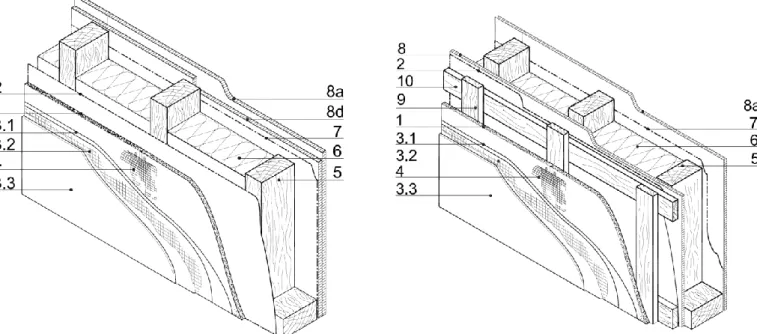
Figure 2.2 - External wall with direct fastening of plates to wood frame: a) direct-mount panels to the frame; b) mounting plates to the wooden crates where the cement slab 1 AQUAPANEL® OUTDOOR; 2 - steam waterproof layer AQUAPANEL® TYVEK StuccoWrap; 3.1 - reinforcing and mortar, adhesive AQUAPANEL 3.2 - mesh for outdoor works; 3.3 - Covered AQUAPANEL plaster; 4 - filler for joints AQUAPANEL - gray and AQUAPANEL tape for joints; 5 - bearing account; 6 - insulating material (Knauf Insulation); 7 - vapor barrier layer; 8 - plasterboard Knauf; 8d - wood chipboard (OSB); 9 - bearing armor; 10 - the basic armor
The lightweight wall systems contains a frame-covering non-exterior protective structure, which withstands the load of wind pressure and its own mass.
2.2 Analysis of existing experience
Development of energy efficient and saving designs and technologies in construction are priority areas of science and technology. Improving the energy efficiency of buildings is possible by reducing the costs of heating and ventilation,
and increasing the resistance to heat of the building envelope relative to the baseline. These goals can be achieved by reducing the impact of possible "cold bridges" on their total thermal resistance. Therefore, many researchers are studying heat transfer in composite constructions.
In recent widely used modular systems, it was determined that the "cold bridges" with the greatest influence have the fastening elements. Elements of fastening, having a much lower coefficient of thermal conductivity compared to a panel thermal isolation, lead to the occurrence of thermal heterogeneity of the structure. The presence of heat-conducting inclusions reduces the durability and reliability of the structur. Evaluation of heat condition of modern modular systems is an urgent task for many scientists.
The company Knauf conducted a study of thermal characteristics of this type of structure for the climatic conditions in different countries of the European Union.
Also in the Russian Federation on the basis of research "Conclusion of the thermal characteristics of panels" defines the value of the thermal resistance for the outer wall of varying height and thickness, with step of rack of the frame 600 mm, were determined and given in the table for non-combustible (NC) mineral wool boards with the density of 37-40 kg / m3 with the calculated values: λ А = 0,042 W / (м · ° С) и λ В = 0,045 Вт / (м · ° С). The results of the given research are summarized in Table 2.1
Table 2.1 The value of the reduced thermal resistance of different structures calculated for Russian Federation
Clear height, m
Adjusted heat resistance, R0, (m · ° C) / W, outdoor wall thickness, mm
150 200 200 + 50
Operating in accordance with SP 131 [2]
A B A B A B
3.3 3.46 3.23 3.88 3.63 5.1 4.77
3.6 3.56 3.32 4.00 3.73 5.22 4.87
For specific geographical areas of Russia, types of home or premises and conditions (A or B) determine the minimum value of the thermal resistance on the outer wall R0 [2]. Then with Table 2.1 determine thickness of the wall with this thermal resistance R0 is not less than the minimum thermal resistance in [2].
In Ukraine DonNACEA conducted the research work "Research teams accordance thermal performance of exterior walls using cement slabs Knauf AQUAPANEL® Cement Board Outdoor and building energy index advanced regulatory requirements of Ukraine." Work is performed under the scientific direction DonNACEA cooperation with LLC "KNAUF Gypsum Kyiv" under the
guidance of Ph.D., head of the department "Building construction and buildings' D. Hohriakova.
In this work, the values of the linear coefficients of heat transfer of KNAUF systems and nodal connections were determined.
2. 3 Classification complete lightweight wall systems
The classification of types of constructions of systems using plates AQUAPANEL® OUTDOOR below.
The classification shows that the system has a variety of designs that can effectively use it in different types of buildings.
1. By appointment:
- for the installation of external wall; - for repair and restoration of the facade;
- to enhance the architectural expressiveness of the facades, the aesthetics of the outer walls
2. By the type of architectural and building systems of buildings in which the system is applied:
- frame-monolithic (to 15 floors);
- low-rise buildings on a frame of a steel frame;
3. By static type:
- bearing (on the wooden frame or steel frame); - self-supporting (in frame-monolithic buildings);
- non-bearing (in hinged facade systems, for facing external walls) 4. By the technology of erection::
- item-collection;
- from ready-made panels.
5. By materials bearing part of a complete system: - the steel frame (Figure 2.1);
- the wooden frame (Figure 2. 2).
6. By the number of contours insulation (frame number counters):
- single (for unheated buildings on racks Knauf CW, for heated buildings on the racks of the steel);
- Double for heatied buildings.
7.By the type of fastening of plates AQUAPANEL® OUTDOOR to bearing parts of the system:
- with direct mounting of panels to the frame (Figure 2.1; Figure 2.2);
- with mounting of plates to the crate, fixed on the racks of the frame of the bearing wall.
8. By the presence of ventilation gap: - with ventilation;
- without ventilation.
When choosing a particular constructive solutions outer wall to consider recommendation that heat isolation should be placed so that it tightly fills the space in rack profile.
2.4 Materials and component parts
All basic materials are performed in accordance with state standards or specifications. Can be used as materials produced directly for systems and other
2.4.1 Elements of frame
Steel galvanized cold-formed profiles, made of galvanized steel of the first class of zinc coating according to [3], [4], are used for the construction of the steel frame. (The weight of one square meter of the coating layer applied on both sides is not less than 275 g / m2)
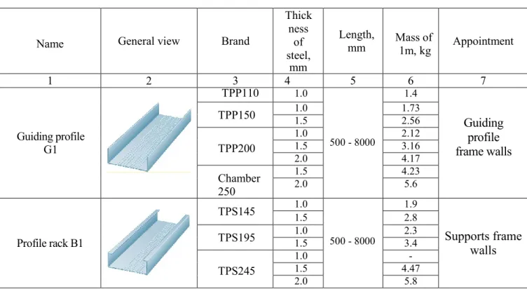
The main parts of the frame are the racks and guiding parts, which can be made from the profiles, which are given in Table 2.2.
Table 2.2 - List of profiles used for racks and guide elements
Name General view Brand
Thick ness of steel, mm Length, mm Mass of 1m, kg Appointment 1 2 3 4 5 6 7 Guiding profile G1 TPP110 1.0 500 - 8000 1.4 Guiding profile frame walls TPP150 1.0 1.5 1.73 2.56 TPP200 1.0 2.12 1.5 3.16 2.0 4.17 Chamber 250 1.5 4.23 2.0 5.6 Profile rack B1 TPS145 1.0 500 - 8000 1.9 Supports frame walls 1.5 2.8 TPS195 1.0 1.5 2.3 3.4 TPS245 1.0 - 1.5 4.47 2.0 5.8
2.4.2 Reinforced cement and mineral boards AQUAPANEL® OUTDOOR
Reinforced cement and mineral plates «AQUAPANEL® OUTDOOR» represent sheet items, consisting of a core based on fine-grained lightweight concrete, all of which plane (front, rear side slit edge), except the end edges reinforced with fiberglass. Physical specifications of the plates are presented in Table 2.3.
Naymenovanye Sharing views Brand Thickne ss of steel, mm Length mm Massa PM 1 kg Appointment Profil Napravlyayus chyy G1 TPP110 1.0 500 - 8000 1.4 Napravlyayusch ye Profile frame walls TPP150 1.0 1.5 1.73 2.56 TPP200 1.0 2.12 1.5 3.16 2.0 4.17 Chamber 250 1.5 4.23 2.0 5.6 Profil Stoech nыy B1 TPS145 1.0 1.9 Racks frame walls 1.5 2.8 TPS195 1.0 1.5 2.3 3.4 TPS245 1.0 - 1.5 4.47 2.0 5.8 Profil napravlyayusch yy c vыrezom G2 CCI-B100 1.0 500 - 8000 1.4 Napravlyayusch ye Profile frame walls CCI-V150 1.0 1.5 1.73 2.56 CCI-V200 1.0 2.12 1.5 3.16 2.0 4.17 Uhlovoy element Kreplenyya DK2 L45h55 1.0 210 0.2 Element kreplenyya beams Profil balochnыy PHS145 1.0
500 - 8000 Profil for peremыchek
1.5 PHS200 1.5 2.0 PHS245 1.5 2.0 PHS300 1.5 2.0 3.74 Profil for lathing PSH28 0.7 1000 - 7000
0.78 Vertical lathing Horizontal and for outdoor
cladding 1.0
Table 2.3 - Physical and technical characteristics of the plates
The name and unit of measurement of the characteristic Value
1 2
Density, kg / m3 1100-1200
Weight of 1 m2 of plate, kg 16
Humidity,% less than 4.0
Water absorption wt% up to 15
Tensile strength in bending in the dry state, MPa at least 0.0 Tensile strength in bending in water-saturated state, MPa at least 9.0
Resistance, cycles at least 75
Bending strength after testing for acid stability (0.5% H2SO4 solution
for 7 days), MPa at least 8.0
Tensile strength after flexural salinity test (3.0% salt sea solution for 7
days), MPa least 10.0
Bending strength after alkali resistance test (solution 5.0% NaOH for 7
days), MPa at least 7.3
Modulus, MPa 4000
Acidity, pH 13
Vapor coefficient, μ, (DIN EN ISO 12572) 19
Estimated vapor coefficient μ, mh / (m2 * h * Pa) 0,033
Vapor resistance, Rp m2 * h * Pa / mg 0.38
Thermal conductivity, W / m2 * K 0.32
Temperature coefficient of linear expansion. Δα * 10-6K-1: Temperature range: - -50 ° C - 20 ° C plus
- plus 20 ° C - + 40 ° C - + 40 ° C - 80 ° C plus
9.33 7.87 3.37 The minimum bend radius, m:
-for plates width 900 mm - Slab width 300 mm
3 1 Destructive pulling force of the screw plate, H 1000
Specific effective activity, Bq no more than 370
Plates have a special rounded shape of the edge, which allows reliable sealing of the joints of the plates. For reinforcement, the edges of the slabs are additionally reinforced with fiberglass (Figure 2.3).
Figure 2.3 - The edge of the AQUAPANEL® OUTDOOR boards and its appearance Nominal sizes of plates brought Table 2.4
Table 2.4 - Nominal dimensions platesAQUAPANEL® OUTDOOR
Characteristic Nominal dimensions of plates, mm
1 2
Length 1200.2400
Width 900
Thickness 12.5
Reinforced cement and mineral plates «AQUAPANEL» have a group of combusting in [5] - G1 (low-combustible). Without reinforcing mesh in [5] plate is non-combustible (NС) building material.
2.4.3 Heat and sound insulating materials
For thermal acoustic insulation the wall systems can use non-combustible (NC) mineral wool plates or other products from various manufacturers. In the studied walls used the fiberglass products manufactured by Knauf Insulation LLC [6], the сharacteristics of which are given in Table 2.5
Table 2.5 - Characteristics of mineral wool «Knauf Insulation» Termo Roll 040
number Characteristic Value
1 2 3
1 Length, mm 6500
2 Width, mm 1200
3 Thickness, mm 150
4 Thermal conductivity, W / (m2K), not more at (10 ± 1) 0,040 5 Thermal conductivity, W / (m2K), not more at (25 ± 1) 0.043 6 Compressibility at the specific load 2000 Pa,%, not more 80 7 Returning after removal Load % Max 98 8 Water with partial immersion for 24 hours,in% weight, not more 45 9 organic Ingredients substances% by weight, not more 5.5
10 Group flammability NF
These materials are made on technology "three in one". Due to this, they perfectly hold heat, protect from extraneous sounds and do not let moisture enter the room. It is produced by rolls in the form of mats.
2.4.4 Wind waterproof materials
Wind waterproof materials that have low water and air permeability, but permeable to water vapor (membranes) are used to protect the insulation layer from climate impacts. Rolled material «Taywek» were used in the study walls. (Tab. 2.6)
Table 2.6 - Geometric characteristics of the material « Tyvek » Name Sharing kind Brand thickne ss, mm Weight g / m2 Length Appointment 1 2 3 4 5 6 7 Material «Tyvek» AquaPanel Tyvek Stucco Wrap 0.18 70 75 Vapor-permeable hydrosensor protective layer for systems without air gap
Physico-Technical indicators roll materials " Tyvek» presented in Table 2.7 Table 2.7 – Physical and technical indicators roll materials «Tyvek»
Name and unit of measurement characteristics Value
1 2
Breaking load at tension along the roll kg/5cm 31.8 Breaking load at tension across the roll, kg/5cm 33.9
Elongation along the roll % 15
Elongation across the roll % 20
Vapor permeability g / m2 per 24 hour 994
The vapor permeability resistance, m2 / h / Pa / mg 0.07 Tensile strength in bending a waterlogged condition, MPa not less than
9.0 Water permeability under pressure, MPa (kg / cm2) 0.02 (0.2)
For the gluing of rolls of hydraulic protection material, a sticky two-sided PLD film based on polyethylene terephthalate film 35 micrometrs thick or other double-sided self-adhesive tape on butyl rubber or acrylic base is used. The film thickness is 35 micrometrs. The length of the roll is 50 m.
2.4.5 Steam insulation materials
To install a vapor barrier layer in the outer frame walls, a vapor barrier film is applied from the side of the room, which is placed between the sheets of the inner skin. As a vapor barrier it is recommended to use a roll material of "Utafol H Special" 0.16 mm thick or other materials with similar properties.
For sizing the joints, a two-sided self-adhesive connecting tape " Utafol l SP1" or other tapes on butyl rubber or acrylic base is used.
2.4.6 Seals
For waterproofing and leveling of the interface unit of the lower frame of the frame of the wall panel and the foundation, it is recommended to use a linoleum liner made of polyethylene foam Linotherm-P 10 mm thick (Table 2.8) or other materials with similar properties.
To seal the vertical seam between adjacent panels of walls, it is recommended to use a 4 mm thick Linotherm-P foam liner (Table 2.8) or other materials with similar properties.
Table 2.8 - Characteristics of Linoterm-P sealing tape
Name General view Brand Thickness
mm Length, m Appointment 1 2 3 4 5 6 Sealing tape Linoterm-P PR 10/50 10 10, 30 To seal the communication nodes PR 10/100 PR 4/50 4 PR 4/100
2.4.7 Connecting products
To fix the AQUAPANEL® OUTDOOR plates to the steel frame, it is recommended to use self-tapping screws with a countersinked milling head, cross-slotted and sharp or drilled with an end that are made of steel grade 10,15, 20 [7] . Anticorrosive coating of screws should provide corrosion resistance for 500 hours in a salt spray chamber. The nomenclature of the screws used is shown in table. 2.9
Table 2.9 - Characteristics of bonding products for fixing AQUAPANEL® OUTDOOR plates to a steel frame
Type General kind Dimensions screws Marking Appointment length, mm diameter, mm 1 2 3 4 5 6 Self-tapping screw with a sharp end (Type SN) 25 4.2 SN 4,2 х 25
Mounting plates to the first layer steel frame with
steel thickness profile of less than 0.7 mm
39 SN 4,2 х 39
Mounting the first and second layer boards to steel frame with steel thickness profile of less
than 0.7 mm
Self-tapping screw with a sharp end (type
SB)
25
3.9
SB 3,9 х 25
Mounting plates to the first layer steel frame with
steel thickness profile of less than 0.7 - 2.0 mm
39 SB 3,9 х 39
Mounting the first and second layer boards to steel frame with steel thickness profile of less
than 0.7 - 2.0 mm
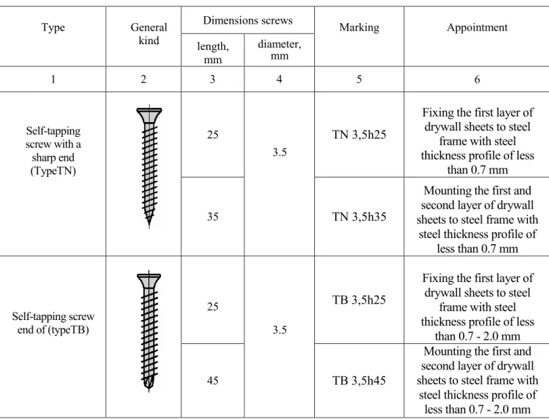
To fix the drywall sheets to the steel frame, it is recommended to use self-tapping screws with a countersinked milling head, cross-slotted and sharp or drilled
with an end that are made of steel grade 10,15, 20 [7] . The nomenclature of the screws used is shown in table. 2.10
Table 2.10 - Characteristics of fastening products for fastening of drywall sheets to steel frame
Type General kind Dimensions screws Marking Appointment length, mm diameter, mm 1 2 3 4 5 6 Self-tapping screw with a sharp end (TypeTN) 25 3.5 TN 3,5h25
Fixing the first layer of drywall sheets to steel
frame with steel thickness profile of less
than 0.7 mm
35 TN 3,5h35
Mounting the first and second layer of drywall sheets to steel frame with
steel thickness profile of less than 0.7 mm Self-tapping screw end of (typeTB) 25 3.5 TB 3,5h25
Fixing the first layer of drywall sheets to steel
frame with steel thickness profile of less
than 0.7 - 2.0 mm
45 TB 3,5h45
Mounting the first and second layer of drywall sheets to steel frame with
steel thickness profile of less than 0.7 - 2.0 mm
To fix the elements of the steel frame to the concrete foundation, "Mango" steel spacer bolts of the M3 type with the "Dacromet" coating were used. To fasten the elements of the steel frame to each other it is recommended to use galvanized self-tapping screws (screws) made of carbon steel produced by SFSintec
2.4.8 Tapes
For reinforcement joints between slabs AQUAPANEL® OUTDOOR glass fabric alkali-resistant reinforcing tape is used, according to standard SP 31-111-2004 [8] , which has characteristics shown in Table 2.11. In preparing the surface under the decorative plaster or facing tile materials used tape width 100 mm, surface preparation under coloring used tape width 300 mm
Table 2.11 - Characteristics of reinforcing tape
Characteristic Indicator
1 2
Weight of 1 m2 tape 127 g / m2
Rated tape thickness 0.3 mm
Nominal number of threads on width of 5 cm
- foundations basic from 20 thread / 5cm - Breaking load in initial state
- basic from
1000 N / 5cm
tape width 100-300 mm
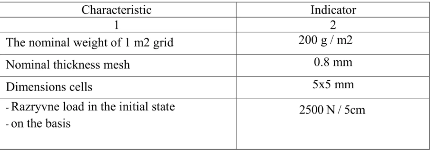
To reinforce the base plaster layer, alkali-resistant glass mesh is used in accordance with SP 31-111, the characteristics of which are given in Tables 2.12
Table 2.12 - Characteristics of fiberglass for reinforcement of basic plaster layer
Characteristic Indicator
1 2
The nominal weight of 1 m2 grid 200 g / m2
Nominal thickness mesh 0.8 mm
Dimensions cells 5x5 mm
- Razryvne load in the initial state - on the basis
2.4.9 Plaster mixes and mixes, primers, adhesives
For sealing joints between slabs AQUAPANEL® OUTDOOR recommended to use mixes "Akvapanel gray" in conjunction with reinforcing tape.
To create a basic layer of plaster is recommended to use painting and adhesive mixes "Knauf Sevener" in TC 5745 [9] or other components designed to create a base layer systems with a thin outer layer of plaster.
For decorative plastering different formulations can be used designed for outdoor use, such as "KNAUF- Diamond" in TC 5745 [10].
For sealing joints between drywall plates is recommended to use a mixes of gypsum based "KNAUF- Fuhenfyuller" in TC 5745 [11, 12, 13] and for sealing joints between moisture drywall plates is recommended to use gypsum putty mixture on the basis of "Knauf Fuhenfyuller Hydro" in TC 5745 [14]
Table 2.13 – Characteristics of a spatula mix on cement basis "Akapanel Gray"
Characteristic Value
1 2
Density at 20 ° C 1500 kg / m3
Open time (at 20 ° C and air humidity
air otnosytelnoy 65%) 50 min.
Time curing vicinity 1 day
Rashod glue
25 ml / 1 running. m. of seam (50 ml / m2 surface)
2.5. Experience of use lightweitght systems
Today in Ukraine these lightweight systems are the most frequently found in cottage construction. The largest Ukrainian manufacturers of modular prefabricated houses based on hidden wooden frame (Figure 2.2) on German technology
Tec». Production of wall panels manufactured in factories staffed latest European equipment, which ensures high accuracy and quality of manufacturing structures, appropriate building standards.
Multi-housing construction in Ukraine is now mainly conducted on cast-frame technology, so the proposed version constructive solution complete system of reliance on the construction of supporting structures overlap, which provides high quality thermal with all the requirements, of course, also prospects of wide application.
2.6 Examples of complete systems
Project: Municipal building - the Supreme Administrative Court of Bulgaria, Sofia (figure 2.5)
Figure 2.5 - Municipal building - the Supreme Administrative Court of Bulgaria, Sofia
The building received an additional floor without the need to strengthen the primary structure of the building due to carelessness design. It was possible to preserve the original style facade.
Completion of construction work accounted for only 7 months, and the work of the court was not broken.Project: Shopping Center Boom, Athens, Greece (figure 2.6)
The outer wall provides alternative designs, such as the false facade.
Boom Mall in Athens, Greece, is an architectural achievement with an attractive appearance, incredible exterior structures created in the main part because the original facade adds a special prestige to the owner of the building.
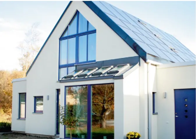
The project "Promenadebyen" (Figure 2.7) is an exclusive apartment-class "luxury" in the harbor district. Odense. The main requirement was reduced planners to ensure that the facade could withstand strong winds and high humidity. Floors of the building and wind loads in combination with high humidity in the harbor were the main criteria in selecting the external structure of the complex.
Characteristics wall facade, in the construction of which was used with a steel frame and termoprofiley AQUAPANEL® OUTDOOR, Provided a solid thin design with high thermal insulation according to strict technical standards of the Nordic countries in terms of energy consumption of buildings.
Termoprofil was used to minimize the problems of "thermal bridges". The method of "dry construction" maximally increased the usable area of the building, which is especially important for expensive waterfront areas, where demand for housing is extremely high.
30
Figure 2.7 - Residential Complex, Denmark
The most energy efficient building Sweden "passive house" (Fig. 2.8), according to the owner, will generate more energy than it consumed. In the
insulation and minimize heat loss, installation of window frames, tightness, ventilation and energy consumption.
Building height of two floors, with a living area of 150 m2, built on a double wooden frame. Extremely high requirements for insulation were provided by the lightweight wall system wooden frame on a double insulated.
This design meets the wall heat transfer coefficient of 0.07 / m2 thickness of insulation 400 and 545 mm and retains heat in the house in winter and ventilated gap removes excess moisture in the summer.
2.7 Problem
The study complete lightweight wall system is characterized by heterogeneity, which is determined by its design features.
Therefore, the applicability of complete systems as walling buildings must be confirmed by calculations as thermal performance design and energy performance of the building a complete system as a whole. This systematic approach taken is set in 2017 DBN V.2.6-31: 2016 Insulation of buildings [1], which entered into force in 05.01.2017
Ukraine's current regulations contain requirements for the design of external facade walls with insulation that is attached to the wall of solid material (brick, concrete, heavy or light, etc.). Features constructive solutions using external wall boards AQUAPANEL® OUTDOOR, namely the presence of a metal or wooden frame, small size of wall elements requires special attention and confirming the heat characteristics, moisture assessment regime, taking into account the impact of heat-conducting inclusions frame element resistance wall heat transfer design in general, and others.
According to the requirements [1] thermal insulation of buildings require the following conditions:
- limiting the minimum reduced resistance to heat enclosure (condition 4); - limiting the temperature difference between the inner surface of the enclosure and internal air (condition 5);
- limiting the minimum temperature on the inner surfaces in the areas of heat-conducting particles (angles, slopes, etc.). That should not exceed the dew point temperature (condition (6);
- conditions for heat resistance in summer and winter periods of operation (condition (8) and (9));
- check the conditions of air permeability (the calculation according to ISO-H B B.2.6: 2016 [15] followed by laboratory testing method DSTU- B V.2.6-189 [17].
The verification of these conditions must be carried out in accordance with the methods developed in recent years in a number of normative documents in the field of energy efficiency, and mathematical modeling of thermal processes (two-dimensional temperature fields) must also be carried out.
Absence of materials for designing, constructions of nodes executed in accordance with accepted in 2016 - 2017 new normative documents of Ukraine on thermal insulation and energy efficiency of buildings, can lead to errors in the design or in the production of work directly on the construction site, and therefore to a significant reduction in the thermal reliability of the structure.
2.8 Conclusion of the second chapter
1. The development of energy-efficient and energy-saving structures and technologies in construction belongs to the priority areas of science and technology. These are the complete lightweight wall systems with the use of AQUAPANEL® OUTDOOR cement slab.
2. Interest in studying the thermal characteristics of complete lightweight wall systems in Ukraine is gradually growing, although in other countries these systems are widely used
3. The complete lightweight wall systems are systems of prefabricated frame structures of external walls, in the constructions of which a large number of different materials are used, therefore it is characterized by thermal engineering heterogeneity.
4. Investigation of the joint operation of the elements of complete systems for compliance with the requirements of heat protection during the operation of buildings will determine the degree of influence of the applied complete systems on the sanitary and hygienic parameters of heat protection.
5. Analysis of the effectiveness of the use of complete systems will allow to assess the economic effect of using a particular complete system from the perspective of reducing operating costs
CHAPTER 3
EVALUATION SHIELDING PROPERTIES COMPLETE SYSTEM BY CAE ANSYSWORKBENCH
3.1 The essence assessment thermo heterogeneous systems
The heat-shielding properties of enclosing structures are estimated from the value of the thermal resistance. For a multi-layered enclosing structure with plane-parallel layers without heterogeneity, the thermal resistance can be calculated by the methods given in the state building codes. The use of these methods for complex heterogeneous structures is sometimes difficult, and often impossible at all, since their surfaces are not isothermal due to the presence of various heat-conducting inclusions, so the given thermal resistance is calculated for these structures. To determine the reduced thermal resistance, it is necessary to measure the total heat flux that passes through the panel in a stationary mode.
The value of the reduced thermal resistance is given by: 𝑅𝑟𝑒𝑑0 =𝑡𝑖𝑛 − 𝑡𝑜𝑢𝑡
𝑄 where, 𝑅пр0 (m · ° C) /W; - thermal resistance
𝑡𝑖𝑛 - internal air temperature, ° C;
t out - ambient air temperature, ° C;
The challenge comes down to determining the heat flux passing through the complete system.
3.2 Using the finite element method for static thermal analysis
Finite Element Method (FEM) - a numerical method for solving differential equations partial and integral equations.
The essence of the method follows from its name. The area in which the solution of the differential equations is sought is divided into a finite number of subdomains (elements). In each of the elements, the form of the approximating function is arbitrarily chosen. In the simplest case this is a polynomial of the first degree. Outside of its element, the approximating function is zero. The values of functions on the boundaries of elements (at nodes) is a solution of the problem and are unknown in advance. The coefficients of approximating functions are usually sought from the condition that the values of neighboring functions on the boundaries between the elements (at the nodes) are equal. Then these coefficients are expressed in terms of the values of the functions at the nodes of the elements. A system of linear algebraic equations is created. The number of equations is equal to the number of unknown values at the nodes on which the solution of the original system is sought, is directly proportional to the number of elements. Since each of the elements is associated with a limited number of neighboring ones, the system of linear algebraic equations has a sparse form, which essentially simplifies its solution.
Finite Element Analysis can determine the behavior of the material, detail, geometric body, mechanical, electrical, thermal host undergoing any external influences, such as physical, mechanical, thermal, electrical, and any others.
The behavior of materials and structures under conditions clearly defined geometrically or physically characterized by thermal deformation that leads to change each element mesh, each node in the network element. They accordingly apply boundary conditions (limiting and blocking, respectively, thermal or physical components, external or internal).
The laws allow heat to design or evaluate design part or parts that are in certain temperature environments. The transfer of heat by three modes such as conduction, convection and radiation. These modes of heat transfer are regulated by special laws:
1. Primary heat law (law of Fourier):
x T k qx (3.1)
whereqx - heat flow in x-direction, W / m2;
k - thermal conductivity which is regarded as a property of the material, W / m 2 K;
x T
- gradient temperature field, K / m.
2. Law of convective heat transfer (Newton's law): )
(T1 T2
h
q (3.2)
where q - convective heat flux, W / m2,
(T1 T2) - temperature difference between two surfaces, K;
h - Coefficient of convective heat transfer, W / m2K.
3. Law of Stefan-Boltzmann law of radiation is absolutely the Black Body: 4
T
q (3.3)
where: q - radiative heat flow, W / m2;
T - the temperature of the Black body completely, K, 4. Feed that radiates nechernoyu surface:
4
T
q (3.4)
- radiation emitting surface property,
5. The net radiative exchange of energy between the surfaces 1 and 2 4 2 4 1 1T T A F F q G (3.5)
F - The factor that characterizes the radiating surfaces;
F - The factor that characterizes the orientation of the radiating surfaces;
А1 - radiating surface area, number 1, m2.
6. Equation Holtzman. General view of the equation system of linear equations dvumirnыh stationary fields:
𝐷𝑥𝜕𝜕22∅𝑥+ 𝐷𝑦𝜕𝜕22∅𝑦− 𝑔∅ + 𝑄 = 0 (3.6)
where: ⌀ - poleva variable
Dx, Dy, g, Q - data constants.
7. The form has fixed problems polevyh form:
−𝛻𝑇𝑘𝛻∅ + 𝑄 = 0 (3.7) where z y x - gradient operator
Any of these laws subordinate to the main rule: stor released ext in Е Е Е Е (3.8) ext in Е
Е , - the amount of energy that passes through the surface of the system;
released
stored
Е - energy, increase or decrease in the amount of thermal internal energy in the closed volume of the system, due to transient processes.
The goal of the work is to find and determine the temperature distribution as a function of time in the transition state. To do this, we use the law of heat transfer, namely the Fourier law. Control matrix equation:
К Т = 𝑓 (3.9)
where K - a global matrix (total stiffness matrix obtained by collecting individual finite element matrices):
1 1 1 1 i j е x x Аk К (3.10)
𝑓 - Global thermal load vector obtained by downloading separate collection vector finite element):
𝑓𝑒 = 𝑄𝑄𝑖
𝑗 (3.11)
T - known global vector must be determined: Те = ТТ𝑖
𝑗 (3.12)
The equation for stationary heat conduction transition in the system (x, y, z) coordinates (depending on the time t), following Equation 3.6 and 3.7 becomes: t T c G z T T k x y T T k x x T k x x y z р ) ( ) ( ) ( (3.13)
where G - the heat generated per unit volume, ρ - density material
cp - specific heat capacity,
kx, ky, kz - thermal conductivity in directions x, y, z, respectively (Equation 2.8 in the case of an isotropic material)
Over studied space temperature discredited as follows:
) ( ) , , ( , , ,y z t 1N x y z T t x Т n i i i (3.14)
n - the number of nodes in the element,
Ti (t)- junction temperature, which depends on time.
The process of solution of equation (3.5) using Galerkin method involves iterative solution because kx, ky, kz depend on temperature, (3.1):
0 ) ( ) ( ) ( d t T c G z T T k x y T T k x x T T k x Ni x y z p (3.15) or (1): С𝑖𝑗𝜕𝑇𝑗 𝜕𝑡 + 𝐾𝑖𝑗 𝑇𝑗 = 𝑓𝑖 (3.16) where: c N N d Сij p i j (3.17) T d hN N d x N x N T k T x N x N T k T x N x N T k K i j j i j z j j i y j j i x ij ( ) ( ) ( ) (3.18) 𝑓𝑖 = 𝑁𝛺 𝑖𝐺𝑑𝛺 − ℎ𝑁𝛤𝑞 𝑖𝑑𝛤𝑞+ 𝑞𝑁𝛤𝑞 𝑖ℎ𝑇𝑎𝑑𝛤𝑞 (3.19)
3.3 Procedure and analysis of complete systems using CAE Ansys Workbench
As a research object, complete thermo-technical heterogeneous lightweight wall systems (family 1 and family 2) were adopted. Their constructions were discussed in more detail in the previous section.
Geometric models were created using CAD Autodesk AutoCAD. From where it was then exported to the AnsysWorkbench environment.
The overall dimensions of the structures are - 1800 × 1500 mm. Racks of single-row construction are located in 600 mm increments, two-row construction racks are located at 400 mm and 600 mm intervals. The thickness of the air layer in the double-row structure is 50 mm.
Geometric models were constructed in accordance with geometric parameters and especially designs (Figure 3.2).
Figure 3.2 - Geometric models of the investigated constructions a) Family 1 b) Family2
The input parameters for modeling process are: thermal parameters of external and internal air (temperature and coefficient of heat transfer), geometrical sizes of structures and thermo-technical indicators of the elements, of which the structure consists (coefficients of thermal conductivity). All data are given in Table 3.1.
Table 3.1 - Input parameters for the simulation process. Thermal parameters of external and internal air
Temperature, ° C Coefficient of heat transfer W / m2 × ° C Outside air -4 23 Inside air 12 8.7
Heat transfer factor of the materials used in the construction
Material Thermal conductivity, W / m2 × ° C AQUAPANEL® Cement slab
OUTDOOR
0.32 Insulating material (Knauf Insulation) 0.04
Steel profiles (UW, CW) 58
Knauf plasterboard 0.15
The air layer 0.02
Geometric figures
Overall dimensions Step bars, mm
single row design 1800 × 1500 600,600,600
double row design 1800 × 1500 400,400,400,600 In environments Ansys Workbeanch investigation process is modeled as a static thermal analysys (fig. 3.3)
Figure 3.3 - The structure of the static thermal analysis of the heterogeneous designs of Ansys Workbeanch.
Initial data modeling is the distribution of temperature fields on the surface structures (Fig. 3.4, 3.5, 3.6 3.7, 3.8, 3.9) and the magnitude of the heat flux, which passes through the structure.
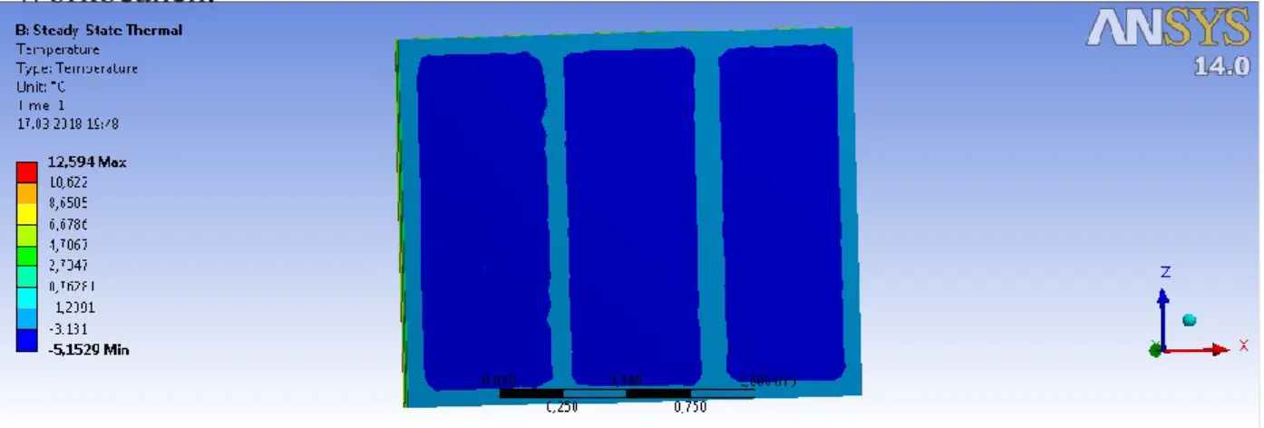
Figure 3.4 - The distribution of temperature fields inside the surface of the investigated structure (family 1) resulting in heat transfer modeling process Ansys Workbeanch.
Figure 3.5 - The distribution of temperature fields outside the surface of the investigated structure (family 1) resulting in heat transfer modeling processAnsys
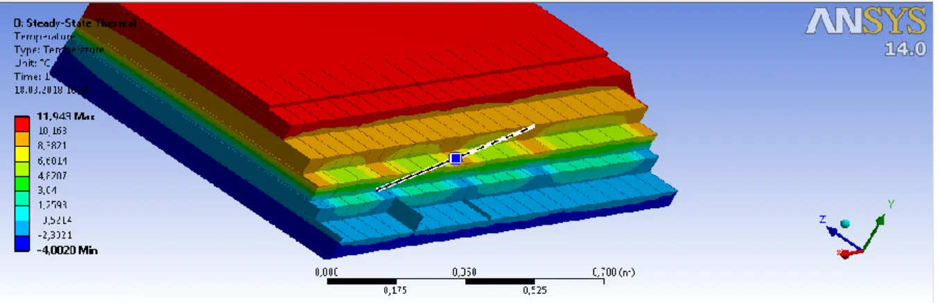
Figure 3.6 - The distribution of temperature fields in the depth of the investigated structure (family 1) resulting in heat transfer modeling processAnsys
Workbeanch.
Figure 3.7 - The distribution of temperature fields in the depths of the investigated structure (family 2) resulting in heat transfer modeling processAnsys
Workbeanch.
Figure 3.8 - The distribution of temperature fields in the thickness of the investigated structure in a stepped section (family 2) resulting in heat transfer
Figure 3.9 - The distribution of temperature fields in the thickness of the investigated structure in a section (family 2) resulting in heat transfer modeling process Ansys Workbeanch.
Heat flow Q, W, which passes through the inline enclosure area of 2.7 m2 is:
Q = 32,4 W/m2 1 m2 for the given design:
Q = 32,4 / 2,7 = 12 W / m2
Heat flow Q, W, which passes through the double row envelope area of 2.7 m2 is:
Q = 8,91 W 1 m2 for the given design:
Q = 8,91 / 2,7 = 3,3 W/m2
According to DBN 2.6-31: 2016 [1], external walls when building new housing or its reconstruction should have such minimum admissible values of thermal resistance:
first temperature zone of Ukraine - 3.3 m2 ·°C/W; for the second - 2.8 m2·°C/W;
Actual thermal resistance of lightweight wall systems , R0, m2·°C/W, defined by the formula:
Q t t R R R R R в н н к в в к н 1 1 0 (3.20)
For single-row design:
) 4 ( 12
тр R R0
Single-row complete lightweight wall systems does not meet the requirements of DBN 2.6-31: 2016 [1].
For double-row design:
85 , 4 3 , 3 ) 4 ( 12 0 R m2·° C/W тр R R 0
Double-row complete lightweight wall systems satisfies the requirements of DBN 2.6-31: 2016 [1].
Linear coefficient of thermal conductivity calculated by the formula:
0
1 R
К (3.21)
Linear coefficient of thermal conductivity for the construction of the family 1: С м W К 0,75 / 3 33 , 1 1
Linear coefficient of thermal conductivity for construction family 2:
С м W К 0,206 / 3 85 , 4 1
Thus, the possibility of using lightweight wall systems as enclosing structures of buildings is verified by calculations of thermophysical parameters of structures. Accepted as an object of study designs have different thermal characteristics. The coefficient of thermal resistance a single-row structure is less than the normative value, therefore the design can not be used as an enclosing structure in any temperature region of Ukraine. The value of this coefficient of double-row design significantly exceeds the normative value, which gives grounds for further studies of various characteristics of this design in harmonizing the building norms of Ukraine.
3.4 Thermotechnical analysis of angular designs of complete systems CAE Ansys Workbench
Geometric models of angular constructions were also created using CAD Autodesk AutoCAD. From where it was then exported to the AnsysWorkbench environment.
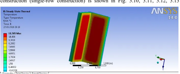
The distribution of temperature fields over the surfaces of the family 1 construction (single-row construction) is shown in Fig. 3.10, 3.11, 3.12, 3.13
Figure 3.10 - The distribution of temperature fields on the inner surface of the angular exploration structure (family 1) resulting in heat transfer modeling
process Ansys Workbeanch.
Figure 3.11 - The distribution of temperature fields on the outer surface of the angular exploration structure (family 1) resulting in heat transfer modeling
Figure 3.12 - The distribution of temperature fields on the internal section of the angular investigated structure (family 1) resulting in heat transfer modeling processAnsys Workbeanch.
Figure 3.13 - The distribution of temperature fields in the external section of the angular investigated structure (family 1) resulting in heat transfer modeling processAnsys Workbeanch.
Heat flow Q, W, which passes through the double row envelope area of 1 m2 is:
Q = 9,15 W/m2
Actual thermal resistance angular design of lightweight wall systems family 1 R0, m2 · ° C / W, defined by the formula 3.20:
𝑅0 = 12 − (−4)
9,15 =
16
9,15 = 1,75 𝑅0 𝑅тр = 1.75 < 3.3 (1 𝑧𝑜𝑛𝑒)
𝑅0 𝑅тр = 1.75 < 2.8 (2 𝑧𝑜𝑛𝑒) System family 1does not meet the requirements [1]
Linear coefficient of thermal conductivity for the angular design family 1 calculated by the formula 3.2:
С м W К 0,75 / 3 75 , 1 1
Similarly modeling structures family 2 (double-row structure) (Fig. 3.14, 3.15, 3.16)
Figure 3.14 - The distribution of temperature fields on the inner surface of the angular exploration structure (family 2) resulting in heat transfer modeling
processAnsys Workbeanch.
Figure 3.15 - The distribution of temperature fields in the external section of the angular investigated structure (family 2) resulting in heat transfer modeling
Figure 3.16 - The distribution of temperature fields on the internal section of the angular investigated structure (family 2) resulting in heat transfer modeling process Ansys Workbeanch.
Heat flow Q, W, which passes through the double row envelope area of 1 m2 is:
Q = 4,02 W/m2
Actual thermal resistance angular design of lightweight wall systems family 2 R0, m2 · ° C / W, defined by the formula 3.20:
𝑅0 = 12 − (−4) 4,02 = 16 4,02 = 3,98 𝑅0 > 𝑅тр 𝑅0 𝑅тр = 3.98 > 3.3 (1 𝑧𝑜𝑛𝑒) 𝑅0 𝑅тр = 3.98 > 2.8 (2 𝑧𝑜𝑛𝑒) System 2 family meets the requirements.
Linear coefficient of thermal conductivity for the angular design family 2 computed using the formula 3.2:
С м W К 0,251 / 3 98 , 3 1
3.5 Conclusions on the third chapter
1. Definition and reduced thermal resistance, coefficients of linear heat transfer can not be performed by methods given in state building codes because investigated walls have the thermal heterogeneity properties.
2. Determine the heat flow, thermal resistance and linear heat transfer coefficients, investigated designs made static heat complete systems analysis using CAE Ansys Workbench.
3. Geometrical model structures were built according to the real family built structures 1 and 2. Physical characteristics of the environment were also specified in accordance with the actual conditions.
4. As a result of the analysis thermal resistance of direct areas of structures family 1 is R0 1.33 m2 · ° C / W Family 2 - R0 4,85m2 · ° C / W. The thermal
resistance angular design family 1 is R0 1.75 m2 · ° C / W, Family 2 - R0 3,98
m2 · ° C / W.
5. Complete System family 1 does not meet the requirements [1] and can not be used in any temperature zone of Ukraine. Complete system 2 system family meets the requirements [1] and can be used throughout in Ukraine.
6. All data used on the real conditions that were obtained by constructing real structures of family 1 and family 2.
CHAPTER 4
CONDUCTING THE EXPERIMENT FOR INVESTIGATION OF THE THERMAL CHARACTERISTICS OF THE SYSTEMS
4.1 Construction of the experimental walls to test results
To check the reliability of the output parameters received during modeling in the environment Ansys Workbeanch these constructions were built in the real environment (according to [22]) with predetermined geometric parameters.
Scheme experimental walls is shown in Figure 4.1, 4.2
Figure 4.1 - Scheme of the experimental wall for the study of thermal properties of a design family: 1 - research design family 1, 2 - Thermal device 3 - a thermometer to measure the ambient temperature, 4 - a thermometer to measure the