©2013 Science Publication
doi:10.3844/ajassp.2013.760.766 Published Online 10 (7) 2013 (http://www.thescipub.com/ajas.toc)
Corresponding Author: Phrut Sakulchangsatjatai, Department of Mechanical Engineering, Faculty of Engineering, Chiang Mai University, 50200, Thailand
FLATTENING EFFECT ON HEAT TRANSFER
CHARACTERISTICS OF A SINTERED-WICK HEAT PIPE
Weeranut Intagun, Pradit Terdtoon and Phurt Sakulchangsatjatai
Department of Mechanical Engineering,
Faculty of Engineering, Chiang Mai University, 50200, Thailand
Received 2013-04-03, Revised 2013-05-21; Accepted 2013-07-04
ABSTRACT
The effect of pipe flattening on heat transfer characteristics and the internal phenomena of a sintered-wick heat pipe has been investigated by using three-dimensional Finite Element Method. The calculation domains were focused at three important regions, i.e., vapor core, wick and wall. The Cartesian coordinates and the three-dimensional tetrahedral elements were applied in this model. The selected total elements were 638,400 to ensure the accuracy. The original diameter and total length of heat pipe were 6 mm and 200 mm, respectively. The composite wick made from sintered copper powder and grooved copper pipe was applied with water as working fluid. The vapor flow was assumed to be laminar and incompressible. The predicted results from the program were validated with the experimental results conducted with all similar controlled parameters. It was found that the predicted wall temperature and thermal resistance agreed well with the experimental data with the standard deviations of ±5.95 and ±32.85%, respectively. Furthermore, the overall thermal resistances of the tubular heat pipes (original diameter of 6 mm), which were flattened into the final thickness of 4.0 and 3.0 mm, decreased from 0.91 to 0.83°C/W due to an increase of the contacted surface for heat transfer surface. However, the overall thermal resistance of a flattened heat pipe with the final thickness of 2.5 mm increased to 0.88°C/W, resulting from drastic increase of pressure drop in narrower vapor core. The pivotal final thickness of flattened heat pipe, which is the minimum thickness of pipe to be flattened, has been analysed to be 2.75 mm (about 45% from original diameter).
Keywords: Flattened Heat Pipe, Three-dimensional Finite Element Model, Final Thickness, Thermal Resistance
1. INTRODUCTION
Recently, urgent need of new cooling techniques applied to a thin packaging structure and high thermal density such as in laptop computer is widely realized. One of such cooking methods is employing heat pipe as heat conveyer from CPU chip to a cooling fan in electronic circuit. The heat pipe is a heat transfer device that combines the principles of both high thermal conductance from the evaporation and condensation in closed container (Chen and Faghri, 1990; Wang and Vafai, 2000). Flattened heat pipe is one of the effective heat transfer device in the thermal management of the
performance of the heat pipe exhibited. The pipe bending by Finite Element Method was studied (Thuchayapong, 2012). It was found that pipe bending affect the thermal performance of tubular heat pipe, when the heat pipe operates at high heat load and small pipe. Although several works have been conducted to explain the characteristics of the flattened heat pipe, few of them attempted to apply the 3D simulation model, from which clearer and reasonable phenomena can be observed. Thus, the aim of this study is to study the effect of pipe flattening on heat transfer resistance (as designated by the temperature distribution) heat pipe by using 3D Finite Element Method (FEM) to clarify the complex features of our heat pipes.
2. MATERIALS AND METHODS
2.1. Mathematical Formulation and Numerical
Procedure
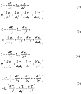
The schematic diagram of flattened heat pipe and the coordinate system was shown in Fig. 1.
Three regions inside heat pipe were focused, i.e., evaporator, adiabatic and condenser sections. The evaporator length (Le), adiabatic length (La) and condenser length (Lc) of flattened heat pipe were showed in Fig. 1. The applied and the removed heat flux in this case were determined from the contacted lower flat area of the heat pipe, under normal operation. In numerical simulation, the vapor flow was assumed to be laminar and incompressible. The properties of vapor were uniform along flattened heat pipe. The wick was assumed to be saturated with the working fluid which was water. The convective heat transfer was neglected (Udell, 1985; ESDU, 1999), the heat conduction equation was, thus, applied in both wick and wall. In addition, the gravity effect was neglected because heat pipe was operated at horizontal mode. Fig. 2 illustrated the cross-sectional area of flattened heat pipe. The Wf was the width of flattened heat pipe. The Thi was the final thickness of flattened heat pipe. The t wick was the thickness of the wick of heat pipe. The t wall was the thickness of the wall of heat pipe. The Ws was the width of contacted surface of the heat source as well as heat sink.
The governing equations in vapor core region included the conservation of mass, momentum and energy equations as follows Equation 1-5:
v v v
u v w
0
x y z
∂ +∂ +∂ =
∂ ∂ ∂ (1)
∂ ∂ ∂ + ∂ ∂ ∂ + ∂ ∂ + ∂ ∂ + ∂ ∂ + ∂ ∂ − = z x w y x v z u y u x u x P v v v v v v v v 2 2 2 2 2 2 2 2 2 0 µ µ (2) ∂ ∂ ∂ + ∂ ∂ + ∂ ∂ + ∂ ∂ ∂ + ∂ ∂ + ∂ ∂ − = z y w z v x v y x u y v y P v v v v v v v v 2 2 2 2 2 2 2 2 2 0 µ µ (3) ∂ ∂ + ∂ ∂ + ∂ ∂ ∂ + ∂ ∂ ∂ + ∂ ∂ + ∂ ∂ − = 2 2 2 2 2 2 2 2 2 0 y w x w z y v z x u z w z P v v v v v v v v µ
µ (4)
v v v
v v, v v
2 2 2
v v v
v 2 2 2
T T T
C u v w
x y z
T T T
k
x y z
∂ ∂ ∂
ρ + +
∂ ∂ ∂ ∂ ∂ ∂ = + + ∂ ∂ ∂ (5)
The governing equations in wick and wall regions were the steady state heat conduction equations as follows Equation 6 and 7:
2 2 2
l l l
eff 2 2 2
T T T
0 k
x y z
∂ ∂ ∂
= + +
∂ ∂ ∂
(6)
2 2 2
s s s
s 2 2 2
T T T
0 k
x y z
∂ ∂ ∂
= + +
∂ ∂ ∂
(7)
Where:
keff = Thermal conductivity of composite wick, W/ (m• °C)
ks = Thermal conductivity of copper wall container, W/(m• °C)
In this study, the vapor velocity of phase change at the liquid-vapor interface was the function of the heat power input, as follows Equation 8 and 9:
v,e
v s e fg Q v
W L h
=
ρ (8)
v,c
v s c fg Q v
W L h
= −
Fig. 1. Schematic diagram of a flattened heat pipe with the coordinates
Fig. 2. Cross-sectional area of flattened heat pipe
Where:
Q = Heat power input, W
Ve = Average vapor velocity at evaporator section, m/sec
Vc = Average vapor velocity at condenser section, m/sec
In our calculation scheme, the original diameter, total length, evaporator length and condenser length, were set as 6, 200, 15 and 70 mm respectively. The selected working fluid was water. The wick used was made from sintered copper powder with the porosity of 0.57. The thicknesses of wick and wall were 0.70 and 0.30 mm respectively. The effective thermal conductivities of the composite wick and copper were 5.97 and 400 W/mK, respectively. The operating temperature was controlled at 60°C. Regarding to the industrial manufacturing requirement, the final thickness of flattened heat pipe
2.2. Experimental Setup and Procedure
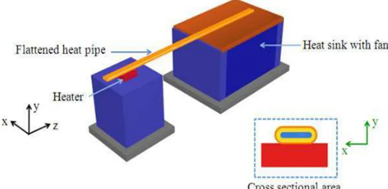
In order to validate the calculation results, the experimental works were also conducted with all parameters of heat pipe set at same condition with 3D simulation section. The samples of heat pipe were made from copper pipe with outside diameter and total length of 6 and 200 mm, respectively. The wick structure was composite wick of groove and homogeneous sintered. The wall and wick structure thickness were 0.3 and 0.7 mm, respectively. The vapor core diameter was 4 mm. The sintered wick made of copper powder of diameter 106-150 µm. The sintering process was performed at a control temperature which specific value. The deionizer water was used as working fluid. The wick was saturated with working fluid. After, the heat pipe was flattened. Regarding the industrial manufacturing requirement, the final thickness of flattened heat pipe was chosen vary from 2.5 to 4.0 mm. The flattened heat pipes were assembled to the heater and heat sink at a horizontal orientation. These were the basic orientations used of heat pipe applications in laptop computer. Heat pipes were heated at the
contacted lower flat area of evaporator section and it was cooled at the contacted lower flat area of condenser section. The thermal grease was used between flattened heat pipe and heater at evaporator section and also between flattened heat pipe and heat sink in condenser section as shown in Fig. 3. The experimental setup and position of thermocouples showed in Fig. 4.
The wall temperature distribution was used to determine the overall thermal resistance of heat pipe which could be compared with the calculation. The experimental procedure started by supplying the heat load of 15 W into the heat pipe. The operating temperature was controlled at 60±2°C. The data logger started recording the temperature of all points when the heat pipe reached steady state operation. After that, the heat load was increased at an incremental step of 5 W until the value of 30 W was obtained. The wall temperature distribution was recorded and the overall thermal resistance was determined to validate with that obtained from the 3D simulation.
Fig. 3. Flattened heat pipe at a horizontal orientation
3. RESULTS AND DISCUSSION
3.1. Effect
of
Pipe
Flattening
on
Wall
Temperature
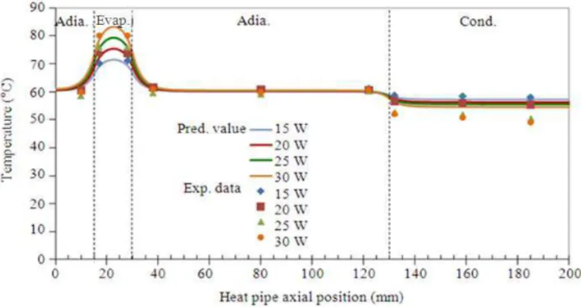
In Fig. 5 the calculated longitudinal wall temperature distribution of the flattened heat pipe with the final thickness of 3 mm was compared with that obtained from the experiment. The heat loads were 15, 20, 25 and 30 W, respectively. It was found that when the heat input increases, the temperature difference between evaporator and condenser sections at the heat input of 30W was 2.3 times higher than that of 15W.
The temperature distribution estimated from the 3D finite element simulation agrees well with that obtained from the experiment with the Standard Deviation (STD) of ±3.69%. Fig. 6 showed the comparison results of wall temperature obtained from 3D simulation and experiment of the heat pipe with final thickness of 4.0, 3.0 and 2.5 mm. The heat load was controlled at 20 W and the operating temperature was 60±2°C. The temperatures distribution estimated from 3D finite element simulation agrees well with those obtained from the experiment with the STD of ±11.34%.
It was noted that the temperature difference of the flattened heat pipe with the final thickness of 4.0 mm was somewhat higher than that of 3.0 mm because of the decreased contacted surface. However, in case of the flattened heat pipe with final thickness of 2.5 mm, the contacted surface was larger, but because of its narrower vapor space the pressure drop sharply increases 7 times. Thus, the temperature difference was higher than that of 3.0 mm about 1.05 times. The same trend was also observed from the experimental results of the flattened heat pipe in (Seok et al., 2002) which was found that, when the final thickness exceeded the specific value, the temperature difference drastically increased. Fig. 7
showed the accuracy of the established 3D simulation program. It was seen that, the accuracy range of the predicted results was ±5.95% which is highly acceptable. It was concluded that, when the final thickness decreases from 4 to 3 mm, the temperature difference steadily decreases from 18.02 to 16.75°C due to an increase of the contacted surface (with the same heat input rate). The accuracy of the established program was ±5.95%.
3.2. Effect of Pipe Flattening on Overall
Thermal Resistance
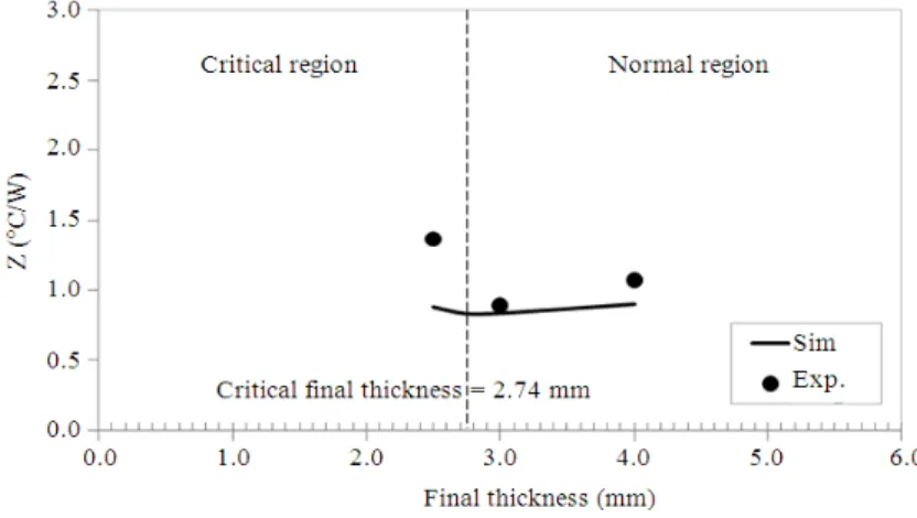
The overall thermal resistance of heat pipe was an important indicator used to present the performance of heat pipe. The result of the overall thermal resistance estimated from the presented 3D simulation and that obtained from the experiment at operating condition of 20 W showed in Fig. 8. It was found that, when the final thickness decreases from 4 to 3 mm, the thermal resistance would decrease from 0.91 to 0.83°C/W resulting from an increase of the contacted surface. However, when heat pipe is further flattened to the specific value, the overall thermal resistance increases to 0.88°C/W. The predicted values agree well with those from experiments with the STD of ±32.85%. However, it is found that the thermal resistance only normal region agree well with experiments with STD of ±12.73%. Similar trend was also observed in (Lin and Wong, 2012) although the different parameters were employed. This can be importantly concluded that, there exists the specific value of the final thickness of flattening process. It was worth to clearly determine this specific value. After the precise statistical analysis was conducted, the critical final thickness was analyzed to be 2.74 mm (approximately 45% decreased from the original diameter). This can be applied in any processes of pipe flattening as an important indication of the allowable final thickness.
Fig. 6. Variable final thickness of flattened heat pipe at heay input 20W
Fig. 7. Comparison of wall temperature between 3D simulation and experiment
4. CONCLUSION
The 3D simulation program to calculate the pressure and temperature distribution of the flattened heat pipe with sintered wick has been successfully established.
When the final thickness decreases from 4 to 3 mm, the temperature difference steadily decreases from 18.02 to 16.75°C due to an increase of the contacted surface (with the same heat input rate). The accuracy of the established program was ±5.95%.
There exists the specific final thickness of the process of pipe flattening which was analyzed to be 45% of the original diameter.
5. ACKNOWLEDGEMENT
The researchers would like to show their appreciation to the support from the strategic scholarships for frontier research network for the Ph.D. program, Thai doctoral degree from office of the higher education commission, Thailand (contract number 244/2550) and Fujikura Electronics (Thailand) Ltd.
6. REFERENCES
Chen, M.M. and A. Faghri, 1990. An analysis of the vapor flow and the heat conduction through the liquid-wick and pipe wall in a heat pipe with single or multiple heat sources. Int. J. Heat Mass Transfer, 33: 1945-1955. DOI: 10.1016/0017-9310(90)90226-K
Do, K.H., S.J. Kim and S.V. Garimella, 2008. A mathematical model for analyzing the thermal characteristics of a flat micro heat pipe with a grooved wick. Int. J. Heat Mass Transfer, 51:
4637-4650. DOI:
10.1016/j.ijheatmasstransfer.2008.02.039
ESDU, 1999. Heat pipes-performance of two-phase closed thermosyphons. IHS ESDU, 133 Houndsditch, London.
Hanzhong, T., H. Zhang, J. Zhuang and J.W. Bowmans, 2008. Experimental study of partially flattened axial grooved heat pipes. Chinese Sci. Bull., 53: 3058-3072. DOI: 10.1007/s11434-008-0396-0
Lin, K.T. and S.C. Wong, 2012. Performance degradation of flattened heat pipes. Applied Thermal
Eng., 50: 46-54. DOI:
10.1016/j.applthermaleng.2012.06.001
Seok, H.M., G. Hwang, H.G. Yun, T.G. Choy and Y. Kang, 2002. Improving thermal performance of miniature heat pipe for notebook PC cooling. Microelectron. Reliab., 42: 135-140. DOI: 10.1016/S0026-2714(01)00226-8
Udell, K.S., 1985. Heat transfer in porous media considering phase change and capillary-the heat pipe effect. Int. J. Heat Mass Transfer, 28: 485-495. Wang, Y. and K. Vafai, 2000. An experimental